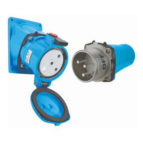
Meltric DS Series User manual

GENERAL
DS and DSN Series products are designed to provide
the safety and functionality of a switch with the con-
venience of a plug & receptacle. They can safely be
used to make and break electrical connections, even
in overload situations and are an approved ‘line of
sight’ disconnect switch.
There are inherent dangers
associated with electrical
products. Failure to follow safety precautions can result
in serious injury or death. These instructions must be
followed to ensure the safe and proper installation, oper-
ation and maintenance of the MELTRIC devices. Before
installation, disconnect all sources of power to the circuit
to eliminate the risk of electrical shock.
RATINGS
DS andDSN Series Switch Rated plugs & receptacles
are UL & CSA listed in accordance with UL Subject
2682, UL 1682 and CSA 22.2 182.1. All are listed
as ‘Branch Circuit Disconnect Switches’ and most are
also horsepower rated and listed as ‘Motor Circuit
Disconnect Switches’. The amperage, voltage,
horsepower, switch and environmental ratings are
indicated on the product labels.
All DS/DSN devices are rated to make and withstand
short circuit currents with appropriate fusing as indi-
cated in Table 1. Some DS and DSN devices are pro-
vided with optional auxiliary contacts that make after
and break before the phase contacts. The ratings for
auxiliary contacts are shown in Table 2.
* Rating applies with fusing up to this amperage. Ratings
are based on tests performed with Ferraz Shawmut
non-time delay current limiting fuses.
INSTALLATION
DS/DSN should be installed by qualied
electricians in accordance with all applicable
local and national electrical codes.
Before starting, verify that the power is off, that the
product ratings are appropriate for the application, and
that the conductors meet code requirements and are
within the capacities of the terminals noted in Table 3.
Main
Contacts
Aux.
Contacts2Min Max
Black
Casings
Max
Blue
Casings
Device Min Max Max
DSN20 – 20 A 14 12 n/a .375 .750 .750
DSN30 – 30 A 14 814 .375 .750 .750
DSN60 – 60 A 14 414 .510 1.25 1.25
DSN1505– 150A 4 2/0 143.700 –1.812
DS20 – 20 A 14 814 .300 –1.380
DS30 – 30 A 14 414 .510 –1.380
DS60 – 60 A 10 2143.500 –1.812
DS100C –100A 10 2143.500 –1.812
DS100 – 100A 4 2/0 143.700 –1.812
DS200 – 200A 4 4/04143.870 –2.400
1 Capacity is based on THHN wire sizes
2Auxiliary contacts are optional and may not be on all products.
3Auxiliary contacts are prewired at the factory.
4 2/0 AWG if part number does not include the ‘A06’ sufx.
5The DSN150 is intended to be wired with conductors rated 75°C
or higher.
General Notes & Precautions
1. Self-tapping screws are provided for use with
some polymeric accessories. High torque may
be required to drive them in. Once they are
seated, care should be taken in order to avoid
over-tightening them against the plastic material.
2. Various handles and cord grip options may be
used. These instructions are based on handles
provided with integral multi-layer bushing cord grips.
3. Wire strip lengths are indicated in Table 4. Strip
lengths for cable sheathing will depend on the
specic application. When used with handles, the
cable sheathing should extend into the handle to
ensure secure cord gripping.
Table 4 - Wire Strip Length – Dimensions A
Device Receptacle Plug/Inlet
Inches mm Inches mm
DSN20 Phase 1/2 13 5/8 16
DSN30 Phase 7/16 11 3/4 19
Auxil. 1/2 13 3/4 19
DSN60 Phase 9/16 14 7/8 22
Auxil. 1/2 13 5/8 16
DSN150 Phase 1 3/16 30 1 3/16 30
DS20 Phase 7/16 11 3/4 19
Auxil. 1/2 13 3/4 19
DS30 Phase 9/16 14 7/8 22
Auxil. 1/2 13 5/8 16
DS60 Phase 15/16 24 15/16 24
DS100C Phase 15/16 24 15/16 24
DS100 Phase 1 3/16 30 1 3/16 30
DS200 Phase 1 3/16 30 1 3/16 30
4. Factory installed auxiliary wires should be
stripped as necessary to make a connection.
Table 5 - Terminal Screw Tightening Torques
Device/Contact Torque Required Screwdriver or
Allen Wrench
in-lbs N-m
DSN20 Phase 15-20 1.7 3 mm or 1/8” precision tip
DSN30 Phase 15 1.7 4 mm or 3/16” precision tip
Auxil. 15 1.7 4 mm or 3/16” precision tip
DSN60 Phase 15 1.7 5 mm or 3/16” precision tip
Auxil. 15 1.7 3 mm or 1/8” precision tip
DSN150 Phase 90 10.2 4 mm hex head
DS20 Phase 15 1.7 4 mm or 3/16” precision tip
Auxil. 15 1.7 4 mm or 3/16” precision tip
DS30 Phase 15 1.7 5 mm or 3/16” precision tip
Auxil. 15 1.7 3 mm or 1/8” precision tip
DS60 Phase 48 5.4 4 mm hex head
DS100C Phase 48 5.4 4 mm hex head
DS100 Phase 90 10.2 4 mm hex head
DS200 Phase 130 14.7 5 mm hex head
5. Wiring terminals are spring assisted to prevent
loosening due to wire strand settlement, vibration
and thermal cycling. NOTICE: Do not over-
tighten the terminal screws. Appropriate tools
and tightening torques are indicated in Table 5.
6. Some auxiliary contacts are factory prewired.
Proper lugs should be used and lugs should be
crimped with the proper tool.
7. The DS100 and DS200 are rated as general
purpose switches, but are not horsepower rated
WARNING! If these devices are installed in
motor power supply applications, warning
labels may be required to advise users not to
disconnect the device under load. Labels are
provided in the package, but should only be
used when required.
8. NOTICE: MELTRIC threaded handles come with
tapered style threads. The use of tting seal
tape is recommended to maintain watertightness
of all NPT ttings and joints.
Assembly for In-Line Connections
Do not overtighten terminal or self-tapping
screws. Tighten screws to the proper torque to
ensure a secure connection.
When most DS/DSN are used as in-line connectors,
nger drawplates should be installed on both the
receptacle and plug in order for the user to more easily
provide the leverage required to connect the device.
On the larger sized devices, (DS100, DSN150 &
DS200) the nger drawplates are not needed because
an easy closing mechanism is provided as standard.
Adjust the bushing diameter to t the cable by removing
inner sections of it as required. Insert the bushing into
the strain relief, then insert the assembly into the
handle and loosely install the compression nut. Insert
the cable through the handle, the thin black drawplate
gasket and nger drawplate (if applicable) and the
color coded gasket. Strip the cable sheath to provide
a workable wire length, being mindful that the sheath
must extend into the handle to achieve a secure cord
grip. Then strip the individual wires to the lengths
indicated in Table 4 and twist the strands of each
conductor together.
Back out the terminal screws on the receptacle (or
inlet) far enough (but not completely) to allow the
conductors to pass, insert the conductors fully into
the proper terminals and tighten the screws with the
appropriate tool to the torque indicated in Table 4.
Compression
Nut
Handle
Strain
Relief Color-Coded
Gasket
Receptacle
(or Inlet)
Bushing
Finger Drawplate Gasket
Finger Drawplate
DS/DSN
SERIES
OPERATING INSTRUCTIONS
ENGLISH
A company of MARECHAL ELECTRIC GROUP
MELTRIC Corporation / 4765 W. Oakwood Park Drive Franklin, WI 53132
INSDS/DSN V
A manufacturer of products using Marechal technology
meltric.com
WARNING
DANGER
CAUTION
NOTICE
ADVERTENCIA
DANGER
CAUTION
AVISO
WARNING
DANGER
CAUTION
NOTICE
ADVERTENCIA
DANGER
CAUTION
AVISO
WARNING
DANGER
CAUTION
NOTICE
ADVERTENCIA
DANGER
CAUTION
AVISO
Device Rating Fuse Type*
DSN20 – 20A 100 kA @ 600 VAC RK1 35A
DSN30 – 30A 100 kA @ 600 VAC RK1 125A
DSN60 – 60A 100 kA @ 600 VAC RK1 110A
DSN150 – 150A 10 kA @ 600 VAC RK1 400A
100 kA @ 600 VAC RK1 225A
DS20 – 20A 100 kA @ 600 VAC RK1 80A
DS30 – 30A 100 kA @ 600 VAC RK1 125A
DS60 – 60A 100 kA @ 600 VAC RK1 250A
DS100C – 100A 100 kA @ 600 VAC RK1 250A
DS100 – 100A 65 kA @ 600 VAC RK5 100A
65 kA @ 600 VAC RK1 175A
DS200 – 200A 65 kA @ 600 VAC RK5 200A
Device 120 VAC 240 VAC 480 VAC 600 VAC
DSN30, DSN60 6 A 3 A 1.5 A 1.2 A
DSN150 1.5 A .75 A .37 A .30 A
DS20, DS30 6 A 3 A 1.5 A 1.2 A
DS60, DS100C 6 A 3 A 1.5 A 1.2 A
DS100, DS200 3 A 1.5 A .75 A .6 A

Verify that the cable jacket extends beyond the strain
relief and into the handle. Assemble the receptacle (or
inlet), the color coded gasket, the nger drawplate, and
the thin black drawplate gasket to the handle with the
four self-tapping screws provided. Adjust the cable loca-
tion so that it will not be under tension inside the handle
and tighten the compression nut to secure the cable.
Assembly for Mounted Receptacles (or Inlets)
In applications where DS or DSN receptacles (or
inlets) are mounted to wall boxes, panels or other
equipment, optimal operation is achieved when the
device is installed with the latch at the top and with
the force from the cable being exerted in a downward
direction opposite the latch.
Insert the cable or wires through the wall box and cut
to allow adequate length, strip the cable sheath as
desired, strip the individual wires to the lengths indicated
in Table 3, and twist the strands of each conductor
together. Back out the terminal screws on the receptacle
(or inlet) far enough (but not completely) to allow the
conductors to pass, insert the conductors fully into
their respective terminals and hand tighten the terminal
screws to the torque indicated in Table 5.
Assemble the receptacle (or inlet) and the color-coded
gasket to the box with the appropriate hardware.
Assemble the mating plug (or receptacle) to the cord
end as indicated in the assembly instructions above
for in-line connections, except there will be no nger
drawplate or associated black gasket.
Hole Pattern for Custom Mounting
In applications where
custom mounting to a panel
or box is being performed,
the clearance and mounting
holes should be drilled as
indicated in the following
diagram and Table 6.
Table 6 - Custom Mounting Dimensions
Model ‘A’ ‘B’ ‘C’
Inches mm Inches mm Inches mm
DSN20 – Recept 2.00 51 1.65 42 .19 5
DSN30 2.25 57 1.89 48 .19 5
DSN60 2.50 64 2.17 55 .19 5
DSN150 4.00 102 3.20 81 .22 5.5
DS20 2.25 57 1.89 48 .19 5
DS30 2.50 64 2.17 55 .19 5
DS60 & DS100C 3.25 83 2.59 66 .22 5.5
DS100 4.00 102 3.20 81 .22 5.5
DS200 4.50 114 3.86 98 .28 7
NOTICE: In order to maintain the Type 4X or IP 66 &
67 protection provided in custom installations, water-
tight seals should be used under the heads of the four
mounting bolts and they must be retained by a lock
washer and nut on the inside of the box or panel.
Alternatively, four blind holes may be drilled and
threaded to accommodate the mounting screws,
provided that the hole depth is sufcient to achieve
adequate gasket compression.
OPERATION
To ensure safe and reliable operation MELTRIC
plugs and receptacles must be used in
accordance with their assigned ratings.
MELTRIC plugs and receptacles can only be used in
conjunction with mating receptacles or plugs manu-
factured by MELTRIC or another licensed producer of
products bearing the TM technology trademark.
MELTRIC plugs & receptacles are designed with dif-
ferent keying arrangements, so that only plugs and
receptacles with compatible contact congurations
and electrical ratings will mate with each other.
Connection
To connect a plug and receptacle, rst depress the pawl
to open the lid on the receptacle, then orient the plug as
shown in gure 1 so that the red dot on the outside of
the casing lines up with the red dot just to the left of the
latch on the receptacle casing. Push the plug partially
into the receptacle until it hits a stop, then rotate the
plug in the clockwise direction until it hits another stop
after about 30° of rotation. At this point, the circuit is
still open. Push the plug straight into the receptacle as
shown in gure 2 until it becomes securely latched in
place. The electrical connection is now made. On in-
line connectors, squeeze the drawplates on both sides
of the device together until the plug latches in place.
On the DS100, DSN150 & DS200 devices, an integral
mechanism provides easy connection of the plug to
the receptacle. With the DS100, DSN150, or DS200
plug partially inserted and rotated 30° so that it is po-
sitioned for connection, place the wire clamps around
the boltheads as shown in gure 3.
To pull the plug into the receptacle, simply push the
handles back along the side of the receptacle and
then push the plug into the receptacle until the plug
is latched in place, as shown in gure 4. After
connection, the mechanism must be released to
allow disconnection of the device.
NOTICE: Additional instructions are provided for
some DS100 receptacle congurations and must be
followed in order to ensure that the closing mecha-
nism is set up to operate properly.
Disconnection
To break the connection, simply depress the pawl
as shown in gure 5 . This will break the circuit and
eject the plug straight out to the rest, or off, position.
The plug contacts are de-energized at this point. To
remove the plug, rotate it counter-clockwise (about
30°) until it releases from the receptacle as shown in
gure 6 . Close and latch the lid on the receptacle.
Achieving Environmental Ratings & Watertightness
For devices rated Type 4, 4X, or 3R, use only
with mating devices having identical markings
to maintain enclosure rating of the mated pair.
Rated ingress protection applies to the device when
the plug and receptacle are mated and latched
together. It also applies to the receptacle when the
lid is latched closed.
Lockout Provisions
All DS and DSN plugs are provided with lockout
provisions. To lockout the plug, insert a locking device
through the hole provided in the casing. This will pre-
vent the plug from being inserted into a receptacle.
DS and DSN receptacles may be purchased with
optional lockout provisions and used with 5/16-inch
shank locks. To lockout the receptacle, close and
latch the lid and then attach the locking device
through the hole provided in the pawl. This will prevent
the lid from being opened for the insertion of a plug.
NOTICE: Attaching the receptacle locking device
with the receptacle lid open will not prevent the in-
sertion of a plug. Lockout of the receptacle is only
accomplished when the lid is locked closed.
MAINTENANCE
Before inspecting, repairing,
or maintaining MELTRIC
products, disconnect electrical power to the receptacle
to eliminate the risk of electrical shock.
MELTRIC products require little on-going mainte-
nance. However, it is a good practice to periodically
perform the following general inspections:
• Check the mounting screws for tightness.
• Verify that the weight of the cable is supported
by the strain relief mechanism and not by the
terminal connections.
• Check the IP gaskets for wear and resiliency.
Replace as required.
• Verify the electrical continuity of the ground circuit.
• Check the contact surfaces for cleanliness and pitting.
Deposits of dust or similar foreign materials can be
rubbed off the contacts with a clean cloth. Sprays
should not be used, as they tend to collect dirt. If
any signicant pitting of the contacts or other serious
damage is observed, the device should be replaced.
Receptacle contacts may be inspected by a qualied
electrician. This should only be done with the power
off. It is accomplished by depressing the numbered
ring around the circumference of the interior on two
opposite points. This will allow the shutter to be
manually turned clockwise as required to permit
access to the contacts. Once the inspection is complete,
the shutter must be rotated counter-clockwise until it
is locked in the closed position.
MANUFACTURER’S RESPONSIBILITY
MELTRIC’s responsibility is strictly limited to the
repair or replacement of any product that does not
conform to the warranty specied in the purchase
contract. MELTRIC shall not be liable for any penal-
ties or consequential damages associated with the loss
of production, work, prot or any nancial loss incurred by
the customer.
MELTRIC Corporation shall not be held liable when
its products are used in conjunction with products not
bearing the TM technology trademark. The
devices that are not marked with the TM tech-
nology trademark shall void all warranties on
the product.
MELTRIC Corporation is an ISO 9001 certied company. Its
products are designed, manufactured and rated in accordance
with applicable UL, CSA and IEC standards. MELTRIC designs
and manufactures its products in accordance with Marechal key-
ing standards established to ensure intermatablility with similarly
rated products manufactured by Marechal Electric Group.
C
A
B
B
INSDS/DSN V
4
56
2
1
3
Wire clamp
around bolthead
Mount with the latching pawl at
the top to counteract the weight
and strain of the plug & cable.
Mount the receptacle
at a downward angle
whenever possible.
WARNING
DANGER
CAUTION
NOTICE
ADVERTENCIA
DANGER
CAUTION
AVISO
WARNING
DANGER
CAUTION
NOTICE
ADVERTENCIA
DANGER
CAUTION
AVISO
WARNING
DANGER
CAUTION
NOTICE
ADVERTENCIA
DANGER
CAUTION
AVISO

Dévissez juste assez les bornes de raccordement de
la prise (ou du raccord d’entrée) pour permettre le
passage des conducteurs, insérez complètement chaque
conducteur dans la borne appropriée et resserrez les
bornes avec l’outil approprié en respectant les couples
indiqués au tableau 4.
Assurez-vous que le revêtement de câble traverse le
serre-câble et pénètre dans la poignée. Fixez la prise
(ou le raccord d’entrée), le joint d’étanchéité à code de
couleur, la plaque de levage et le mince joint d’étanchéité
noir de la plaque de levage à la poignée à l’aide des
quatre vis autotaraudeuses fournies. Placez le câble de
façon à ce qu’il ne soit pas sous tension à l’intérieur de la
poignée et serrez l’écrou de compression pour l’empêcher
de bouger.
Assemblage pour Prises (ou Raccord d’Entrées)
Montées
Lorsque les prises (ou les raccords d’entrées) DS ou
DSN sont installées dans des boîtiers muraux, sur des
panneaux ou sur un autre équipement, il faut, pour
assurer un fonctionnement optimal, que le verrou du
dispositif se trouve sur le dessus et que la force du câble
soit exercée vers le bas, en direction opposée du verrou.
Installez le dispositif de façon à ce
que le cliquet de verrouillage soit
sur le dessus an de contrer
l’effet du poids et de la
tension du
câble et de
la che.
Installez la prise selon un
angle descendant dans la
mesure du possible.
Insérez le câble ou les fils dans le boîtier mural et
coupez-le à une longueur adéquate, dénudez le câble au
besoin, dénudez les fils selon les longueurs indiquées au
tableau 3 et entortillez ensemble les torons métalliques
de chaque conducteur. Dévissez juste assez les
bornes de raccordement de la prise (ou du raccord
d’entrée) pour permettre le passage des conducteurs,
insérez complètement chaque conducteur dans la borne
appropriée et resserrez les bornes à la main en respectant
les couples indiqués au tableau 5.
Fixez la prise (ou le raccord d’entrée) et le joint
d’étanchéité à code de couleur au boîtier au moyen des
attaches appropriées. Fixez la fiche d’accouplement
(ou le raccord d’entrée) à l’extrémité du cordon, comme
l’indiquent les directives d’assemblage en série ci-dessus,
en omettant la plaque de levage et son joint d’étanchéité.
Dimensions des Trous pour Montage sur Mesure
Dans le cas d’un montage sur mesure dans un panneau
ou un boîtier, les dégagements et les trous de fixation
doivent respecter les dimensions indiquées dans le
graphique et le tableau 6 ci-dessous.
Tableau 6 – Dimensions pour Montage sur Mesure
Modèle ‘A’ ‘B’ ‘C’
Pouces mm Pouces mm Pouces mm
DSN20 – Prise 2,00 51 1,65 42 0,19 5
DSN30 2,25 57 1,89 48 0,19 5
DSN60 2,50 64 2,17 55 0,19 5
DSN150 4,00 102 3,20 81 0,22 5,5
DS20 2,25 57 1,89 48 0,19 5
DS30 2,50 64 2,17 55 0,19 5
DS60 et DS100C 3,25 83 2,59 66 0,22 5,5
DS100 4,00 102 3,20 81 0,22 5,5
DS200 4,50 114 3,86 98 0,28 7
MISE EN GARDE : Pour maintenir l’indice de protection
de type 4X ou IP66 et IP67 dans les assemblages sur
mesure, apposez des joints étanches sous la tête des
boulons de fixation, ainsi qu’une rondelle de blocage et un
écrou du côté intérieur du boîtier ou du panneau. Vous
pouvez également percer et fileter quatre trous bornes
pour y insérer les vis de montage, pour autant que les
trous soient suffisamment profonds pour permettre une
compression adéquate des joints.
OPÉRATION
WARNING
DANGER
CAUTION
NOTICE
ADVERTENCIA
DANGER
CAUTION
AVISO
Pour assurer une utilisation sécuritaire et fiable, les
fiches et prises MELTRIC doivent être utilisées
conformément à leur classification respective.
Les fiches et prises MELTRIC peuvent uniquement être
utilisées avec des fiches ou des prises homologues
fabriquées par MELTRIC ou par un autre fabricant
autorisé de produits portant la marque de commerce
technologique TM. Les fiches et les prises
MELTRIC sont conçues selon différentes configurations
et ne peuvent donc être connectées à des fiches
et des prises possédant des configurations et des
caractéristiques électriques homologues.
Connexion
Pour brancher une fiche et une prise, abaissez d’abord
cliquet de verrouillage pour ouvrir le couvercle du socle de
la prise, puis placez la fiche dans la position illustrée à la
figure 1 de façon à ce que le point rouge à l’extérieur de
l’enveloppe soit aligné sur le point rouge situé à gauche
du verrou se trouvant sur le socle de la prise. Enfoncez
partiellement la fiche dans la prise jusqu’à ce qu’elle bloque,
puis tournez-la dans le sens des aiguilles d’une montre
jusqu’à ce qu’elle bloque de nouveau après une rotation de
30°. À cette étape, le circuit est toujours ouvert. Enfoncez
la fiche dans la prise jusqu’à ce qu’elle soit engagée,
comme l’illustre la figure 2. La connexion électrique est
alors établie. Dans le cas des connecteurs en ligne,
pressez les plaques de rapprochement situées de chaque
côté du dispositif jusqu’à ce que la fiche soit engagée.
Les dispositifs DS100, DSN150 et DS200 sont dotés d’un
mécanisme intégral qui facilite la connexion de la fiche
et de la prise. Après avoir inséré partiellement la fiche
et lui avoir fait faire une rotation de 30° afin qu’elle soit
en position de connexion, placez les crochets de la prise
autour des agrafes fixes du connecteur, comme l’illustre
la figure 3.
Pour insérer la fiche dans la prise, poussez simplement
vers l’arrière les poignées situées sur le côté de la prise,
puis enfoncez la prise jusqu’à ce qu’elle soit engagée,
comme l’illustre la figure 4. Une fois la connexion établie,
le mécanisme doit être déclenché pour permettre le
débranchement du dispositif.
MISE EN GARDE : Certaines configurations de prise
DS100 sont accompagnées de consignes supplément-
aires qui doivent être suivies pour veiller à ce que le
mécanisme de fermeture soit correctement enclenché.
Déconnexion
Pour couper la connexion, abaissez simplement le
cliquet de verrouillage, comme l’illustre la figure 5. Cette
manœuvre aura pour effet de couper le circuit et d’éjecter
la fiche jusqu’en position d’arrêt. Les contacts de la fiche
sont alors hors tension. Pour retirer la fiche, faites-lui faire
une rotation (d’environ 30°) dans le sens contraire des
aiguilles d’une montre jusqu’à ce qu’elle soit éjectée de la
prise, comme l’illustre la figure 6. Fermez et verrouillez le
couvercle du socle de la prise.
Classification Environnementale et Étanchéité
WARNING
DANGER
CAUTION
NOTICE
ADVERTENCIA
DANGER
CAUTION
AVISO
Les dispositifs affichant un indice de protection de
type 4, 4X ou 3R doivent uniquement être utilisés
avec des dispositifs homologues affichant des
cotes identiques pour conserver le même indice une fois
la paire raccordée.
L’indice de protection s’applique au dispositif lorsque
la fiche et la prise sont raccordées et verrouillées. Il
s’applique également à la prise lorsque le couvercle du
socle de celle-ci est fermé et verrouillé.
Cadenassage
Toutes les fiches DS et DSN peuvent être cadenassées.
Pour ce faire, insérez un cadenas dans le trou prévu à cet
effet dans l’enveloppe. Ainsi, la fiche ne pourra plus être
insérée dans une prise.
Les prises DS et DSN peuvent également être dotées
d’un dispositif de cadenassage compatible avec les
cadenas munis d’une tige de 0,8 cm. Pour cadenasser
la prise, fermez et verrouillez le couvercle, puis insérez le
cadenas dans le trou du loquet de verrouillage. Ainsi, il ne
sera plus possible d’ouvrir le couvercle afin d’insérer une
fiche dans la prise.
MISE EN GARDE : L’utilisation d’un cadenas lorsque le
couvercle du socle de la prise est ouvert n’empêchera
pas l’insertion d’une fiche. Le couvercle doit être fermé et
verrouillés pour permettre le cadenassage de la prise.
ENTRETIEN
Avant d’inspecter, de réparer ou
de procéder à l’entretien de
produits MELTRIC, coupez l’alimentation électrique de la
prise pour éliminer tout risque de décharge électrique.
Les produits MELTRIC nécessitent peu d’entretien.
Cependant, il est recommandé d’effectuer périodiquement
les inspections suivantes :
• Assurez-vous que les vis de montage sont bien serrées.
• Assurez-vous que le poids du câble est supporté par le
serre-câble, et non par les bornes.
• Vérifiez l’état et l’usure des joints IP, et remplacez-les au
besoin.
• Vérifiez la continuité électrique du circuit de mise à la terrre.
• Examinez les surfaces de contact pour vous assurer de
leur propreté et de l’absence de piqûres.
Utilisez un linge propre pour enlever les dépôts de
poussière ou de corps étrangers. N’utilisez pas de
produits en vaporisateur, car ils ont tendance à ramasser
la saleté. Si vous observez un grand nombre de piqûres
ou d’autres dommages importants sur les surfaces de
contact, le dispositif doit être remplacé.
Les contacts de la prise doivent être inspectés par un
électricien qualifié, et seulement lorsque l’alimentation
électrique est coupée. Pour ce faire, abaissez l’anneau
numéroté situé autour de la circonférence intérieure
en deux points opposés. Vous pourrez alors tourner
manuellement le mécanisme d’obturation dans le sens
des aiguilles d’une montre afin d’accéder aux contacts.
Une fois l’inspection terminée, tournez le mécanisme
d’obturation dans le sens contraire des aiguilles d’une
montre jusqu’à ce qu’il revienne en position fermée.
RESPONSABILITÉ DU FABRICANT
La responsabilité de MELTRIC se limite strictement à
la réparation ou au remplacement de tout produit non
conforme à la garantie précisée dans le contrat d’achat.
MELTRIC ne peut être tenue responsable des pénalités
ou des dommages indirects découlant d’une perte de
production, de travail, de bénéfices, ou de toute perte
financière subie par le client.
MELTRIC ne peut être tenue responsable lorsque ses
produits sont utilisés avec d’autres qui ne portent pas
la marque de commerce technologique TM.
L’utilisation de produits MELTRIC avec des dispositifs
homologués qui ne portent pas la marque de commerce
technologique TM a pour effet d’annuler toute
garantie.
La société MELTRIC possède la certification ISO 9001, Ses
produits sont conçus, fabriqués et classés selon les normes
UL, CSA et IEC applicables. MELTRIC conçoit et fabrique
ses produits selon les standards de Marechal et assure la
compatibilité de ses produits avec ceux de maréchal ayant les
spécifications similaires.
INSDS/DSN V
C
A
B
B
56
4
3
Crochets autour
des agrafes
1 2

GENERAL
Los productos de la serie DS y DSN están diseñados para
proveer la funcionalidad y seguridad de un interruptor con
la conveniencia de un tomacorriente y clavija. Pueden
utilizarse para conectar y desconectar, de manera
segura, conexiones eléctricas aun en caso de una
sobrecarga además de estar aprobadas como interruptor
desconectador de “Línea de Vista”. Siga las instrucciones
que aparecen a continuación para garantizar el uso
correcto e instalación del producto.
Hay peligros inherentes con los
p productos eléctricos. El no siguir
las precauciones de seguridad puede resultar en lesiones
graves o muerte. Seguir estas instrucciones para mantener
una segura y apropiada instalación, uso y mantenimiento
de los productos MELTRIC. Antes de instalar desconecte
todas las fuentes al circuito para eliminar el riesgo de
shock eléctrico.
RANGOS
La serie DS y DSN MELTRIC de tomacorrientes y clavijas
están aprobadas como interruptor por UL & CSA, con-
forme a los incisos de los estándares UL 2682, UL 1682
y CSA 22.2 182.1. Han sido clasicados como “Interrup-
tores para Desconexión de Circuitos Derivados” y la
mayoría están clasicados por potencia nominal en HP
como “Interruptores para Desconexión de Motor”. Los
valores en amperes, tensión, potencia en HP, clasicación
como interruptor y protección ambiental del envolvente se
indican en las etiquetas del producto.
Todos los dispositivos clasicados como interruptor están
diseñados para soportar y exceder corrientes de corto
circuito con la protección de fusibles adecuada como se
indica en la Tabla 1. Algunos de los dispositivos DS y
DSN están proporcionados con contactos auxiliares op-
cionales. Los cuales se conectan después y desconectan
antes de los contactos de fase. Los rangos de operación
de los contactos auxiliares se encuentran en la tabla 2.
Dispositivo Rango del fusible Tipo*
DSN20 – 20A 100 kA @ 600 VAC RK1 35A
DSN30 – 30A 100 kA @ 600 VAC RK1 125A
DSN60 – 60A 100 kA @ 600 VAC RK1 110A
DSN150 – 150A 10 kA @ 600 VAC RK1 400A
100 kA @ 600 VAC RK1 225A
DS20 – 20A 100 kA @ 600 VAC RK1 80A
DS30 – 30A 100 kA @ 600 VAC RK1 125A
DS60 – 60A 100 kA @ 600 VAC RK1 250A
DS100C – 100A 100 kA @ 600 VAC RK1 250A
DS100 – 100A 65 kA @ 600 VAC RK5 100A
65 kA @ 600 VAC RK1 175A
DS200 – 200A 65 kA @ 600 VAC RK5 200A
* Los Rangos aplican con fusibles hasta este rango en amperes.
Los Rangos están basados en el desempeño en pruebas con
fusibles limitador de corriente sin retardo de tiempo Ferraz
Shawmut.
Dispositivo 120 VAC 240 VAC 480 VAC 600 VAC
DSN30, DSN60 6 A 3 A 1.5 A 1.2 A
DSN150 1.5 A .75 A .37 A .30 A
DS20, DS30 6 A 3 A 1.5 A 1.2 A
DS60, DS100C 6 A 3 A 1.5 A 1.2 A
DS100, DS200 3 A 1.5 A 0.75 A 0.6 A
INSTALACIÓN
Los DS y DSN deben ser instalados por
electricistas calicados de acuerdo con todas
las normas de instalaciones eléctricas vigentes
aplicables locales o federales.
Antes de iniciar, verique que el circuito no este energi-
zado, que el rango del producto es el apropiado para la
aplicación, que los conductores cumplan con la normatividad
vigente y que se encuentran dentro de la capacidad de
las terminales que se mencionan en la Tabla 3.
Tabla 3 - Capacidad de Alambrado1(AWG) Rango del Cable DE
Contactos
Principales Contactos
Auxiliares2Min Max
Carcasas
negras
Max
Carcasas
azules
Dispositivo Min Max Max
DSN20 – 20 A 14 12 n/a .375 .750 .750
DSN30 – 30 A 14 814 .375 .750 .750
DSN60 – 60 A 14 414 .510 1.25 1.25
DSN150 –150A 4 2/0 143.700 –1.812
DS20 – 20 A 14 814 .300 –1.380
DS30 – 30 A 14 414 .510 –1.380
DS60 – 60 A 10 2143.500 –1.812
DS100C –100A 10 2143.500 –1.812
DS100 – 100A 4 2/0 143.700 –1.812
DS200 – 200A 44/04143.870 –2.400
1 La Capacidad se basa en las dimensiones del cable THHN.
2Los contactos auxiliares son opcionales y pueden no incluirse en
todos los productos.
3Los contactos auxiliares se cablean previamente en fábrica.
4 2/0 CAE si el número de parte no incluye el sujo “A06”.
5El DSN150 está diseñado para uso con conductores de 75 C o más.
Notas & Precauciones Generales
1. Se proporcionan tornillos autorroscantes para ser
utilizados con algunos componentes poliméricos,
puede requerirse de un gran torque para colocarlos,
una vez hecho esto, evite apretarlos demasiado
contra el material plástico.
2. Pueden utilizarse varias empuñaduras y conectores
tipo glandula para el conductor, estas instrucciones
están basadas en empuñaduras que utilizan un
conectores tipo glandula para el cable con un
empaque multicapa.
3. El largo del cable requerido sin aislamiento para
introducir en las terminales se indica en la Tabla 4,
este largo dependerá de la aplicación especíca,
cuando se utiliza con manijas el largo del conductor
sin aislamiento deberá de llegar al fondo de la
terminal para asegurar un sujeción segura del cable.
Tabla 4 - Largo del Cable sin Aislamiento – Dimensiones
Dispositivo/Polo Tomacorriente Clavija
Pulgadas mm Pulgadas mm
DSN20 Fase 1/2 13 5/8 16
DSN30 Fase 7/16 11 3/4 19
Auxil. 1/2 13 3/4 19
DSN60 Fase 9/16 14 7/8 22
Auxil. 1/2 13 5/8 16
DSN150 Fase 1 3/16 30 1 3/16 30
DS20 Fase 7/16 11 3/4 19
Auxil. 1/2 13 3/4 19
DS30 Fase 9/16 14 7/8 22
Auxil. 1/2 13 5/8 16
DS60 Fase 15/16 24 15/16 24
DS100C Fase 15/16 24 15/16 24
DS100 Fase 1 3/16 30 1 3/16 30
DS200 Fase 1 3/16 30 1 3/16 30
4. El largo del cable sin aislamiento de los contactos
auxiliarles pre cableados debe ser lo suciente-
mente necesario para hacer una conexión.
5. Las terminales están asistidas por un resorte (arillo
de seguridad) para evitar que se aojen debido a
vibración, asentamiento o ciclo térmico. AVISO: No
se deberá dar un apriete excesivo a las mismas,
herramientas apropiadas y torques especícos
deberán ser utilizados como se indica en la Tabla 5.
Tabla 5 - Torques para los Tornillo de las Terminales
Dispositivo/Polo Torque Desarmador Requerido
o Llave Allen
Pulg.-lb N-m
DSN20 Fase 15-20 1.7 3 mm or 1/8” pulg. tip de precision
DSN30 Fase 15 1.7 4 mm or 3/16” pulg. tip de precision
Auxil. 15 1.7 4 mm or 3/16” pulg. tip de precision
DSN60 Fase 15 1.7 5 mm or 3/16” pulg. tip de precision
Auxil. 15 1.7 3 mm or 1/8” pulg. tip de precision
DSN150 Fase 90 10.2 4 mm de cabeza hexagonal
DS20 Fase 15 1.7 4 mm or 3/16” pulg. tip de precision
Auxil. 15 1.7 4 mm or 3/16” pulg. tip de precision
DS30 Fase 15 1.7 5 mm or 3/16” pulg. tip de precision
Auxil. 15 1.7 3 mm or 1/8” pulg. tip de precision
DS60 Fase 48 5.4 4 mm de cabeza hexagonal
DS100C Fase 48 5.4 4 mm de cabeza hexagonal
DS100 Fase 90 10.2 4 mm de cabeza hexagonal
DS200 Fase 130 14.7 5 mm de cabeza hexagonal
6. Algunos de los contactos auxiliares son pre cableados
en la fábrica. Se debe utilizar terminales de compre-
sión y herramienta adecuada para hacer una
conexión.
7. Los dispositivos DS100 y DS200 están clasicados
como interruptores para usos generales, pero no
desconexión para rango en caballos de fuerza.
ADVERTENCIA! Si estos dispositivos son instalados
para alimentar motores, etiquetas de advertencia de
berán de ser utilizadas para advertir al personal
indicando que no se deberá de desconectar el dis
positivo energizado (bajo carga). Las etiquetas de
advertencia se proveen con el paquete pero solo de
berán de utilizarse cuando sea requerido.
8. AVISO: Se recomienda el uso de cintas selladoras
para las cuerdas para impedir el ingreso de agua en
las uniones y juntas del tubo conduit (NPT)
Ensamble de las Tomacorrientes Tipo Extensión
No sobre apriete las terminales o los tornillos
autorroscantes. Apriete los tornillos a su torque
apropiado para mantener una conexión segura.
Cuando un DS y DSN es utilizado como extensión se
recomienda instalar “placas para facilitar el cierre con los
dedos”, tanto en las tomacorrientes como en las clavijas
para que el usuario pueda tener la palanca necesaria para
realizar la conexión del dispositivo. En los dispositivos más
grandes (DS100, DSN150 y DS200) las “placas para facilitar
el cierre con los dedos” no son necesarias porque un me-
canismo de cierre fácil se incluye como estándar.
Ajuste el diámetro del Empaque Multicapa removiendo
cada una de las mismas según se requiera, inserte el
Empaque en el Relevador de Esfuerzo, luego inserte el
ensamble en la empuñadura enseguida libremente inserte
la tuerca de compresión. Inserte el cable en la manija, el
empaque negro delgado, la placa de cierre con los dedos
(si es necesario) y el empaque codicado por color. Rem-
ueva el aislamiento del cable para proveer un área de
trabajo adecuada, tomando en cuenta que se deberá de
introducir en la manija lo suciente como para proveer un
agarre seguro del cable. Entonces remueva el aislamiento
de cada uno de los conductores la distancia que se indica
en la Tabla 3 y tuerza los hilos de cada conductor para
que se unan.
Aoje los tornillos de las terminales en la tomacorriente
(o clavija) lo suciente (pero no completamente) para
permitir que pase el conductor, inserte completamente
el conductor en las terminales apropiadas y apriete los
tornillos con la herramienta apropiada al torque indicado
en la Tabla 4.manija.
A company of MARECHAL ELECTRIC GROUP
MELTRIC Corporation / 4765 W. Oakwood Park Drive Franklin, WI 53132
INSDS/DSN V
A manufacturer of products using Marechal technology
meltric.com
DS/DSN
SERIE
INSTRUCCIONES DE OPERACIÓN
ESPAÑOL
Manija
Relevador de
Esfuerzo Empaque
Codicado
por Color
Tomacorriente
Empaque
Multicapa
Empaque para la Placa
de Cierre con los Dedos
Placa de Cierre con los Dedos
Tuerca de
Compresión
WARNING
DANGER
CAUTION
NOTICE
ADVERTENCIA
DANGER
CAUTION
AVISO
WARNING
DANGER
CAUTION
NOTICE
ADVERTENCIA
DANGER
CAUTION
AVISO
WARNING
DANGER
CAUTION
NOTICE
ADVERTENCIA
DANGER
CAUTION
AVISO

Verique que el aislamiento del cable se extienda más allá
del relevador de esfuerzo y dentro de la manija. Ensamble
el tomacorriente (o clavija), el empaque codicado por
color, la placa de cierre con los dedos y el empaque negro
delgado a la manija con los 4 tornillos autorroscantes
suministrados. Ajuste el cable para que no esté bajo tensión
dentro de la manija y apriete la tuerca de compresión para
asegurar el cable.
Ensamble para la instalación de las Tomacorrientes
(o Clavijas)
En aplicaciones en donde los tomacorrientes (o clavijas)
DS o DSN son instaladas en cajas de conexiones para
montaje en pared, paneles u otro equipo la operación
optima se logra cuando el gatillo se instala en la parte
superior con la fuerza ejercida hacia abajo del cable en la
dirección opuesta.
Inserte el cable o alambre a través de la caja de conex-
iones y corte permitiendo un largo adecuado, elimine el
aislamiento tanto como sea deseado, quiete el forro de
los conductores al largo indicado en la Tabla 3, y tuerza
las puntas de cada conductor para unirlas. Aoje el tor-
nillo de las terminales en la tomacorriente (o clavija) lo
suciente (pero no completamente) para permitir que el
conductor pase, inserte el conductor completamente en
su respectiva terminal y apriete manualmente el tornillo al
torque indicado en la Tabla 4.
Ensamble el tomacorriente (o clavija) y el empaque
codicado por color a la caja con la tornillería adecuada.
Ensamble la clavija (o tomacorriente) al nal del cable
como se indican en las instrucciones de ensamble ya
descritas para extensiones, excepto que no habrá placas
de cierre con los dedos o el empaque negro delgado
asociado.
Dimensiones de Barrenos para Montaje Especial
En aplicaciones en donde se
requiere montaje especial a
un panel o caja está siendo
realizado, los barrenos y la
distancia entre ellos deberán
de hacerse de acuerdo
con el diagrama y la tabla
siguiente.
Tabla 6 - Dimensiones de Barrenos para Montaje Especial
Modelo ‘A’ ‘B’ ‘C’
Pulgadas mm Pulgadas mm Pulgadas mm
DSN20–Tomacor 2.00 51 1.65 42 .19 5
DSN30 2.25 57 1.89 48 .19 5
DSN60 2.50 64 2.17 55 .19 5
DSN150 4.00 102 3.20 81 .22 5.5
DS20 2.25 57 1.89 48 .19 5
DS30 2.50 64 2.17 55 .19 5
DS60 & DS100C 3.25 83 2.59 66 .22 5.5
DS100 4.00 102 3.20 81 .22 5.5
DS200 4.50 114 3.86 98 .28 7
AVISO: Para mantener la protección Type 4X o IP 66 &
67 requerida en instalaciones especiales, se deberán de
utilizar sellos a prueba de agua en las cabezas de los
cuatro tornillos de montaje y deben ser retenidos por una
rondana de presión y un tuerca en el interior de la caja
de conexiones o el panel. Alternativamente 4 barrenos
ciegos pueden ser taladrados y/o roscados para insertar
los 4 tornillos de montaje.
OPERACIÓN
Para asegurar la operación segura y conable de
los tomacorrientes y clavijas MELTRIC se deberán
de utilizar de acuerdo con sus capacidades.
Solo pueden utilizarse en conjunto con tomacorrientes y
clavijas MELTRIC y otro fabricante autorizado de los pro-
ductos que ostenten la marca registradeTM.
MELTRIC diseña sus tomacorrientes y clavijas con posi-
ciones de bloqueo diferentes de tal manera que solo las
clavijas y tomacorrientes que tienen las mismas congura-
ciones de contactos y voltajes pueden acoplarse entre sí.
Conexión
Para conectar un tomacorriente y clavija, primeramente
presione el gatillo para abrir la tapa del tomacorriente y
luego oriente la clavija como se indica en la gura 1 de
tal manera que el punto rojo en la parte exterior de la
clavija se esté alineado con el punto rojo en a la izquierda
del gatillo en el tomacorriente. Empuje la clavija parcial-
mente in el tomacorriente hasta que llegue al tope,
entonces gire la clavija en dirección de las manecillas del
reloj hasta que llegue al tope después de girar aproxi-
madamente 30°, en este punto el circuito sigue abierto,
empuje la clavija hacia el tomacorriente como se muestra
en la gura 2, hasta que esté asegurada en su lugar, la
conexión eléctrica se ha realizado. En los tomacorrientes
y clavijas utilizadas como extensiones apriete las placas
para el cierre con los dedos en los dos lados del
dispositivo hasta que se asegure en su lugar.
En los dispositivos DS100, DSN150 y DS200 un me-
canismo integral provee una conexión fácil de la clavija
en el tomacorriente. Con las clavijas de las DS100,
DSN150 y DS200 parcialmente insertadas y giradas 30°
de tal forma que estén en posición para conectarse,
ponga arillos de alambre en las cabezas de los tornillos
como se muestra en la gura 3.
Para insertar la clavija dentro del tomacorriente simple-
mente empuje los manerales a cada lado del dispositivo
hasta que la clavija esté asegurada en su lugar como
se muestra en la gura 4, después de la conexión el
mecanismo deberá de ser removido para permitir la
desconexión del dispositivo.
AVISO: Instrucciones adicionales son proveídas para
algunas conguraciones de tomacorrientes DS100 y
deberán de ser seguidas para asegurar que el
mecanismo de cierre opere adecuadamente.
Desconexión
Para desconectar, simplemente presione el gatillo como
se muestra en la gura 5. Esto abrirá el circuito y
expulsara la clavija directamente a la posición de
descanso o fuera, en este punto los contactos de la
clavija están desenegizados, para remover la clavija gire
la clavija en sentido contrario de las manecillas del reloj
(cerca de 30°) hasta removerla del tomacorriente como
se muestra en la gura 6, cierre la tapa y asegúrela al
tomacorriente.
Protección Contra el Ingreso de Agua y Rangos
Ambientales
Para los dispositivos tipo 4, 4X o 3R use
únicamente para acoplarlos los tomacorrientes y
clavijas con los rangos idénticos para mantener la
protección requerida en el par.
El rango de protección solo es alcanza do cuando el
tomacorriente y clavija están cerrados y asegurados por
el gatillo. También aplica para el tomacorriente cuando la
tapa está asegurada con el gatillo.
Accesorios de Bloqueo
Todas las clavijas de los modelos DS y DSN pueden
ser bloqueadas o etiquetadas. Para bloquear o etiquetar
inserte en el barreno el dispositivo de bloqueo o etiquetado
provisto en el cuerpo de la clavija, esto prevendrá que se
pueda insertar la clavija en el tomacorriente.
Los modelos de tomacorrientes DS y DSN pueden ser
adquiridos con dispositivos opcionales de bloqueo o
etiquetado y utilizados con candados con un diámetro de
5/16-pulgadas. Para bloquear el tomacorriente, cierre la
tapa y asegúrela e inserte el dispositivo de candado en el
barreno que se encuentra en el gatillo. Esto impedirá que
la tapa sea abierta e insertada la clavija.
AVISO: Instalar el dispositivo de candado con la tapa
abierta no impedirá la inserción de la clavija. El bloqueo
del tomacorriente solo se puede lograr cuando la tapa
está cerrada y asegurada por el gatillo y con el dispositivo
de candado instalado.
MANTENIMIENTO
Antes de inspeccionar, reparar
o mantener los productos
MELTRIC desconecte la alimentación al tomacorriente
para eliminar el riesgo de shock eléctrico.
Los productos MELTRIC requieren de muy poco manten-
imiento de cualquier manera es muy recomendable que se
realicen las siguientes prácticas de inspección general:
• Revise el apriete de los tornillos de montaje.
• Verique que el peso del cable este soportado en el
relevador de esfuerzos y no en las terminales de
conexión.
• Revise el desgaste y ajuste del empaque IP.
Intercámbielo según se requiera.
• Verique la continuidad eléctrica del circuito de tierra.
• Revise la limpieza y desgaste de la supercie de
los contactos.
Depósitos de polvo o materiales ajenos similares pueden
ser limpiados con un trapo limpio. Aerosoles no deben
ser utilizados por que atraen suciedad. Si un desgaste
severo en los contactos o cualquier otro daño serio en el
dispositivo son encontrados, el dispositivo deberá de ser
reemplazado.
Los contactos del tomacorriente pueden ser inspeccionados
por un electricista calicado, esto deberá de ser realizado
con el equipo desenergizado, esto puede ser realizado
presionando el arillo numerado gris colocado en la
circunferencia interior del dispositivo en dos puntos
opuestos, esto permitirá que el tapa de bloqueo se
mueva manualmente en el sentido de las manecillas del
reloj para permitir el acceso a los contactos. Una vez que
la inspección a terminado la tapa de bloqueo deberá de
ser girada en el sentido opuesto a las manecillas del reloj
hasta regresarla a su posición de bloqueo.
RESPONSABILIDAD DEL FABRICANTE
La responsabilidad de MELTRIC está limitada estrict-
amente a la reparación y o reemplazo de cualquier
producto que no cumpla con la garantía especicada en
el contrato de compra. MELTRIC no puede ser respons-
abilizado por fallas, daño a consecuencia de la perdida
de producción o cualquier perdida nanciera en la que
incurra el cliente.
MELTRIC Corporation no puede ser responsabilizado
cuando sus productos son utilizados en conjunto con otra
marca que no tenga la marca registrada TM. El uso
de dispositivos acoplables que no tengan la marca regis-
trada TM invalidara toda garantía en el producto.
MELTRIC Corporation es una compañía certicada ISO
9001. Sus productos están diseñados, manufacturados y
con rangos de acuerdo con las normas aplicables UL, CSA
y IEC. Como todos los miembros de la asociación
MELTRIC diseña y manufactura sus productos de acuerdo
con los estándares BECMA para que tengan intercam-
biabilidad con productos similares manufacturados por otros
miembros.
El montaje con el gatillo en la
parte superior contrarresta el
peso y la tensión ejercidos por la
clavija y el cable
Monte el tomacorriente
en una posición en
ángulo hacia abajo
cuando sea posible
C
A
B
B
INSDS/DSN V
4
56
2
1
3
Arillo de alambre
alrededor de la
cabeza del tornillo
WARNING
DANGER
CAUTION
NOTICE
ADVERTENCIA
DANGER
CAUTION
AVISO
WARNING
DANGER
CAUTION
NOTICE
ADVERTENCIA
DANGER
CAUTION
AVISO
WARNING
DANGER
CAUTION
NOTICE
ADVERTENCIA
DANGER
CAUTION
AVISO
This manual suits for next models
11
Table of contents
Other Meltric Switch manuals
Popular Switch manuals by other brands
Trumen
Trumen LSVR Series instruction manual
Renkforce
Renkforce 1268678 operating instructions

HP
HP 372284-001 user guide
PCB Piezotronics
PCB Piezotronics 685B Series Installation and operating manual

Accton Technology
Accton Technology Zilla Dual-Speed Hub-3008R Quick installation guide
SWI
SWI L-Series Installation and operation manual
