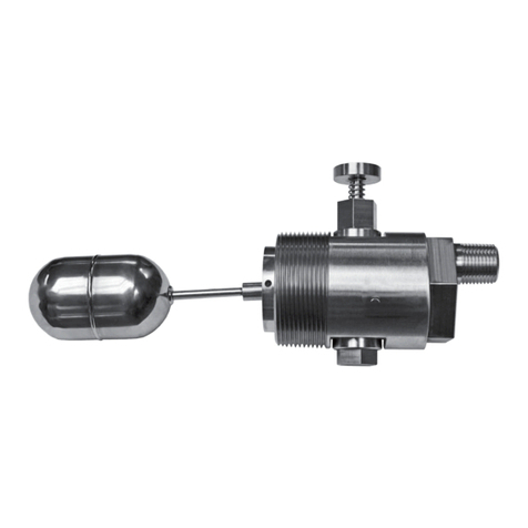
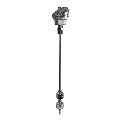
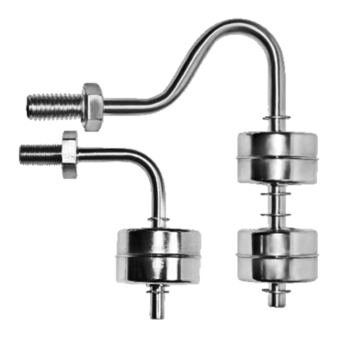
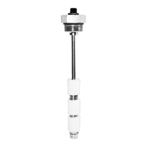
SWI L-Series User manual

L-Series: LIQUID LEVEL
FLOAT SWITCH
Single-Point, Vertically-Mounted Liquid Level Float Switch
INSTALLATION AND OPERATIONS MANUAL
L001, L002, L003, L170, L175, L176,
L177, L178, L180, L190 AND L195
L001
L002
L003
L170
L176
L180
L190
L195

2L-SERIES SINGLE-POINT, VERTICALLY-MOUNTED LIQUID LEVEL FLOAT SWITCH
This manual provides information on the L-Series,
Single-Point, Vertically-Mounted Liquid Level
Float Switch. It is important that all instructions
are read carefully and followed sequentially.
Detailed instructions are included in the Complete
Installation section of this manual.
Conventions Used in this Manual
Certain conventions are used in this manual to convey
specic types of information. General technical
material, support data and safety information are
presented in narrative form. The following styles are
used for notes, cautions and warnings:
Notes
Notes contain information that augments or claries
an operating step. Notes do not normally contain
actions and often follow the procedural steps to
which they refer.
Cautions
Cautions alert the technician to special conditions
that could injure personnel, damage equipment, or
reduce a component’s mechanical integrity. Cautions
are also used to alert the technician of unsafe
practices, the need for special protective equipment,
or specic materials. In this manual, a caution
indicates a potentially hazardous situation which, if
not avoided, may result in minor to moderate injury.
Notice of Copyright and Limitations
Copyright © 2015 Solutions With Innovation, LLC;
All rights reserved.
Solutions With Innovation reserves the right to make
changes to the product described in this manual at
any time without notice. Solutions With Innovation
makes no warranty with respect to the accuracy of the
information in this manual.
Warranty
All Solutions With Innovation Mechanical Level and
Flow Controls are warranted free of defects in materials
and workmanship for one full year from the date of
the original factory shipment. If returned within the
warranty period; and, upon factory inspection of
the control, the cause of the claim is determined to
be covered under the warranty; then, Solutions With
Innovation will repair or replace the product at no cost
to the purchaser (or owner) other than transportation.
Solutions With Innovation shall not be liable for
misapplication, labor claims, direct or consequential
damage, or expenses arising from the installation or
use of the equipment. There are no other warranties
expressed or implied, except special written warranties
covering specic Solutions With Innovation products.
Quality Assurance
The Quality Assurance System in place at Solutions
With Innovation guarantees the highest level
of quality throughout the company. Solutions With
Innovation is committed to providing full customer
satisfaction; both in quality products and in quality
service.
Contacts
Phone: 203-729-6434 Mon-Fri, 9 AM - 5 PM EST
Fax: 203-729-0541 for General Inquiries
Email: sales@innovativesensing.com
READ THIS MANUAL PRIOR TO INSTALLATION

3
L-SERIES SINGLE-POINT, VERTICALLY-MOUNTED LIQUID LEVEL FLOAT SWITCH
L-Series: LIQUID LEVEL
FLOAT SWITCH
Single-Point, Vertical Mount
TABLE OF CONTENTS
L001,L002,L003,L170,L175,L176,
L177, L178, L180, L190 AND L195
1.0 Installation
1.1 Unpacking.............................................................................4
1.2 Before You Begin................................................................4
1.2.1 Site Preparation...........................................................4
1.2.2 Equipment and Tools.................................................4
1.3 Mounting...............................................................................5
1.3.1 Threaded Mounting....................................................5
1.4 Wiring....................................................................................5
2.0 Preventative Maintenance
2.1 What To Do..........................................................................6
2.1.1 Inspect Entire Unit Periodically.................................6
2.1.2 Inspect Connections Monthly...................................6
2.1.3 Keep Unit Clean..........................................................6
2.2 What To Avoid.....................................................................6
3.0 Reference Information
3.1 Description...........................................................................7
3.2 Theory of Operation..........................................................7
3.3 Troubleshooting...................................................................7
3.3.1 External Causes...........................................................7
3.3.2 Unit Causes...................................................................8
3.4 Agency Approvals................................................................8
3.5 Specications........................................................................9
3.5.1 Physical Specications................................................9
3.5.2 Electrical Specications..............................................9
3.5.3 Dimensional Specications......................................10
3.6 Notes...................................................................................10
3.7 Model Congurator...........................................................11
3.8 Replacement Parts.............................................................11

4L-SERIES SINGLE-POINT, VERTICALLY-MOUNTED LIQUID LEVEL FLOAT SWITCH
1.0 INSTALLATION
This section provides detailed procedures on properly installing the L-Series Single-Point, Vertically-Mounted
Liquid Level Float Switch.
CAUTION! IF THE EQUIPMENT IS USED IN A MANNER NOT SPECIFIED BY THE MANUFACTURER, PROTECTION
PROVIDED BY THE EQUIPMENT MAY BE IMPAIRED.
1.1 UNPACKING
Unpack the instrument, carefully. Make sure that all components have been removed from the packing
material. Inspect all components for damage. Report any concealed damage to the carrier within 24 hours
of receiving. Compare the contents with the packing slip and report any discrepancies to the factory
immediately. Record the sales order number and/or serial number for future reference when ordering parts.
Before Proceeding to Installation, Complete the Following:
• Inspect all components for damage. Report any damage to the carrier within 24 hours of receiving.
• Record the model and serial numbers for future reference when ordering parts.
Model Number
Serial Number
1.2 BEFORE YOU BEGIN
CAUTION! DURING THE INSTALLATION OF THE SINGLE-POINT, VERTICALLY-MOUNTED LIQUID LEVEL SWITCH,
THE FLOAT AREA MUST BE KEPT FREE OF METALLIC PARTICLES THAT MIGHT BE ATTRACTED TO THE FLOAT’S
INTERNAL MAGNET.
1.2.1 Site Preparation
Ensure that the length and the inside diameter of the mounting is sized correctly to accommodate the
L-Series Single-Point, Vertically-Mounted Liquid Level Float Switch.
1.2.2 Equipment and Tools
No special equipment or tools are required to install the L-Series Single-Point, Vertically-Mounted Liquid
Level Float Switch.
The Following Are Recommended:
• Wrenches, thread sealant, gaskets and/or bolting as required for the process connection.

5
L-SERIES SINGLE-POINT, VERTICALLY-MOUNTED LIQUID LEVEL FLOAT SWITCH
1.3 MOUNTING
The L-Series Single-Point, Vertically-Mounted Liquid Level Float Switch is available in a variety of threaded
mountings. These devices can be installed from the bottom or top of the tank. The switches should be
mounted in an area clear of turbulence or direct streams.
1.3.1 Threaded Mounting
How to Install an L-Series Single-Point, Vertically-Mounted Liquid Level Switch:
1 Apply either Teon®tape or an
appropriate thread sealant to
the mounting threads to prevent
galling.
2 Engage the thread by hand to
avoid unnecessary damage.
3 Using a wrench, rotate the unit
clockwise until it is tight within
the mounting.
1.4 WIRING
CAUTION! OBSERVE ALL APPLICABLE ELECTRICAL CODES AND PROPER WIRING PROCEDURES.
Contact Protection:
In order to maintain the life and reliability of the internal reed switch, it is essential to provide protection
when switching inductive loads. When the current breaks, the energy stored in the load generates a high
frequency voltage across the switch contacts. If the voltage is large enough, it can initiate arcing and cause
the contacts to weld together. Damage can ultimately be prevented by suppressing the voltage. Through
the use of a diode for DC circuits and a resistor-capacitor network for AC circuits, contact protection will
ensure reliable performance from the reed switch.
TOP MOUNT BOTTOM MOUNT
RED
RED
RED
RED
ORANGE
BLACK
N.C.
N.O.
RED
NORMALLY-OPEN
Dry Condition
NORMALLY-CLOSED
Dry Condition
SPST Reed Switch:
1 Connect the wiring to the red switch leads or
terminals, as illustrated below.
SPDT Reed Switch:
1 Connect the wiring to the proper
switch leads or terminals, as
illustrated below.
Dry Condition
ANGLED MOUNT
30° MAX.

6L-SERIES SINGLE-POINT, VERTICALLY-MOUNTED LIQUID LEVEL FLOAT SWITCH
2.0 PREVENTATIVE MAINTENANCE
Periodic inspections are necessary to maintain the proper functionality of the L-Series Single-Point, Vertically-
Mounted Liquid Level Switch. The switch is a safety device that protects the equipment it serves. A systematic
program of preventative maintenance should be implemented at the time of installation. If the following
instructions are completed routinely, the switch will provide continuous, reliable protection.
2.1 MAINTENANCE PROCEDURES
2.1.1 Inspect Unit Periodically
Verify that there are no cracks or chipped surfaces on the oat or stem. Should the unit become damaged,
obtain a replacement immediately.
2.1.2 Inspect Connections Monthly
L-Series Single-Point, Vertically-Mounted Liquid Level Switches may be vulnerable to excessive heat and
moisture. Under these conditions, the electrical wire insulation can periodically break or peel away. As a
result, the bare wires may become exposed to the elements and cause damages.
• Inspect all wiring, carefully and replace any wires exhibiting signs of brittle insulation.
• Inspect all electrical connections to ensure tightness.
• Repair or replace any wiring, if necessary.
2.1.3 Keep Unit Clean
Periodic cleanings of the oat, stem and magnet assembly will ensure the continual, uninterrupted
movement of the mechanism. Always keep the open area between the enclosures clean and free of any
potential interferences. Objects and debris may cause systematic interruptions and a loss in equipment
functionality.
2.2 WHAT TO AVOID
NEVER LEAVE THE SWITCH WIRING EXPOSED TO THE ELEMENTS.
NEVER PLACE A JUMPER WIRE ACROSS THE TERMINALS TO “CUT-OUT” THE CONTROL. If a jumper is necessary
for testing purposes, ensure that it is removed prior to placing the control into service.
NEVER USE IN SYSTEMS CONTAINING IRON PARTICLES. The magnet within the oat assembly can attract the particles
and become jammed.

7
L-SERIES SINGLE-POINT, VERTICALLY-MOUNTED LIQUID LEVEL FLOAT SWITCH
3.0 REFERENCE INFORMATION
This section illustrates an overview of the L-Series Single-Point, Vertically-Mounted Liquid Level Switch, as
well as information on troubleshooting common problems, agency approval listings, and detailed physical,
functional and performance specications.
3.1 DESCRIPTION
The L-Series Single-Point, Vertically-Mounted Liquid Level Switch
is a oat-actuated device designed to be vertically mounted within a
tank or process vessel through threaded connections. The low-cost
switch is ideal for OEM applications where a single-point high or low
level alarm is desired.
3.2 THEORY OF OPERATION
The switching action is achieved through the use of an internal
magnet within the oat assembly and its interaction with the switch
mechanism. As the liquid level uctuates inside the tank, the oat
follows. Its magnetic eld actuates the switch inside the stem and
closes an electrical circuit.
3.3 TROUBLESHOOTING
The L-Series Single-Point, Vertically-Mounted Liquid Level Switch is designed and engineered for trouble-
free operation over a wide range of operating conditions. Common problems are discussed in terms of their
symptoms and recommended corrective actions.
3.3.1 External Causes
An initial indication of improper operation is the failure of the controlled equipment to function (pumps
will not start or stop, signal lamps fail to light, etc). If these symptoms occur, whether at the time of
installation or during routine service thereafter, check for potential external causes rst:
• Blown Fuses
• Tripped Reset Button(s)
• Open Power Switch
• Faulty Equipment Controlled By the Level Switch
• Defective Wiring to the Level Switch
FLOAT SWITCH DIAGRAM

8L-SERIES SINGLE-POINT, VERTICALLY-MOUNTED LIQUID LEVEL FLOAT SWITCH
3.3.2 Unit Causes
If a thorough inspection of any external causes fails to locate the problem, proceed to an inspection of
the unit, itself. DISCONNECT POWER TO THE LEVEL SWITCH BEFORE PROCEEDING.
SYMPTOM PROBLEM SOLUTION
THE UNIT IS UNRESPONSIVE. ELECTRICAL FAILURE. USE AN ELECTRICAL CONTINUITY
CHECKER TO DETERMINE IF THE
SWITCH IS FUNCTIONAL. IF THE SWITCH
DOES NOT OPERATE PROPERLY
WHEN ACTIVATED, THE ENTIRE LEVEL
SWITCH MUST BE REPLACED.
THE UNIT DOES NOT ACTIVATE WHEN
THE FLOAT CHANGES POSITION.
THE UNIT IS JAMMED. REMOVE THE LEVEL SWITCH
FROM SERVICE. CHECK THE FLOAT
ASSEMBLY FOR OBSTRUCTIONS OR
ACCUMULATION OF PARTICLES WHICH
MAY CAUSE BINDING. IF BINDING IS
PRESENT IN THE FLOAT ASSEMBLY
AND CANNOT BE CLEARED BY NORMAL
CLEANING PROCEDURES, THE ENTIRE
CONTROL MUST BE REPLACED.
THE UNIT ONLY FUNCTIONS WHEN IT IS
NOT IN SERVICE.
LIQUID IS NOT ENTERING THE VESSEL. CHECK TO ENSURE THAT LIQUID IS
ENTERING THE TANK OR VESSEL. A
CLOSED VALVE OR CLOGGED PIPELINE
MAY PREVENT MOVEMENT OF THE
LIQUID IN THE VESSEL.
THE UNIT ONLY FUNCTIONS WHEN IT IS
NOT IN SERVICE.
THE TANK LEVEL IS NOT HIGH ENOUGH
TO HAVE THE FLOAT FUNCTION.
CHECK THE FLOAT TO MAKE SURE IT
IS BUOYANT IN THE LIQUID. THE TANK
OR VESSEL MUST HAVE AN ADEQUATE
LIQUID LEVEL.
THE FLOAT IS NOT BUOYANT. THE FLOAT IS COLLAPSED AND/OR
FILLED WITH LIQUID.
CHECK THE FLOAT FOR RUPTURES,
DEFORMATION, AND ANY LIQUID
TRAPPED INSIDE THE ASSEMBLY. IF
THE FLOAT IS FILLED WITH LIQUID OR
HAS COLLAPSED, THE ENTIRE LEVEL
SWITCH MUST BE REPLACED. DO NOT
ATTEMPT TO REPAIR THE FLOAT.
ALL COMPONENTS WITHIN THE LEVEL
SWITCH ARE IN WORKING ORDER, BUT
THE UNIT STILL DOES NOT FUNCTION.
AN EXTERNAL PROBLEM. REPEAT AN INSPECTION OF THE
EXTERNAL CONDITIONSAS DESCRIBED
IN SECTION 3.3.1.
If you are still in doubt about the condition or performance of your control, consult the factory for further instructions.
3.4 AGENCY APPROVALS
AGENCY APPROVED MODEL(S) FILE NUMBER AREA CLASSIFICATION
UL L001, L002, L003, L170, L175, L176,
L177, L178, L180, L190 & L195
E203716 RECOGNIZED UNDER UL508 MOTOR
CONTROLLERS & NJ0T8 MOTOR
CONTROLLERS

9
L-SERIES SINGLE-POINT, VERTICALLY-MOUNTED LIQUID LEVEL FLOAT SWITCH
3.5 SPECIFICATIONS
3.5.1 Physical Specications
MODEL PROCESS
TEMP.
MAX.
PRESSURE
FLOAT
SPECIFIC
GRAVITY
RECOMMENDED
MINIMUM
LIQUID S.G.
STEM
MATERIAL
FLOAT
MATERIAL
L001 -40° to +150° F 150 PSIG 0.65 0.95 Polypropylene Polypropylene
L002 -40° to +150° F 150 PSIG 0.63 0.84 Polypropylene Polypropylene
L003
-40° to +150° F 150 PSIG 0.65 0.87 Polypropylene Polypropylene
-40° to +150° F 50 PSIG 0.49 0.66 Polypropylene Polypropylene
-40° to +150° F 50 PSIG 0.74 1.00 PVC PVC
-40° to +180° F 150 PSIG 0.47 0.63 Nylon Buna
L170
-40° to +180° F
(In Water) 150 PSIG 0.47 0.63 Brass Buna
-40° to +225° F
(In Oil) 150 PSIG 0.47 0.63 Brass Buna
-40° to +180° F 150 PSIG 0.47 0.63 Stainless Steel Buna
L175 -40° to +300° F 100 PSIG 0.52 0.69 Brass Stainless Steel
-40° to +300° F 100 PSIG 0.52 0.69 Stainless Steel Stainless Steel
L176 -40° to +300° F 300 PSIG 0.74 1.00 Brass Stainless Steel
-40° to +300° F 300 PSIG 0.74 1.00 Stainless Steel Stainless Steel
L177 -40° to +300° F 600 PSIG 0.72 0.96 Brass Stainless Steel
-40° to +300° F 600 PSIG 0.72 0.96 Stainless Steel Stainless Steel
L178 -40° to +300° F 275 PSIG 0.65 0.86 Brass Stainless Steel
-40° to +300° F 275 PSIG 0.65 0.86 Stainless Steel Stainless Steel
L180 -40° to +180° F 150 PSIG 0.48 0.64 Brass Buna
-40° to +180° F 150 PSIG 0.48 0.64 Stainless Steel Buna
L190
-40° to +180° F 150 PSIG 0.43 0.57 Brass Buna
-40° to +180° F 150 PSIG 0.43 0.57 Stainless Steel Buna
-40° to +300° F 120 PSIG 0.60 0.80 Stainless Steel Stainless Steel
-40° to +140° F 150 PSIG 0.43 0.57 PVC Buna
L195 -40° to +300° F 750 PSIG 0.59 0.79 Stainless Steel Stainless Steel
3.5.2 Electrical Specications
SIGNAL OUTPUT Switch Closure
TYPE OF CONTACTS SPST, SPDT
TYPE OF SWITCHES Hermetically-Sealed, Dry Contact Reed Switch
SWITCH RATING 50 VA, 240 VAC/VDC Max.
100 VA, 240 VAC/VDC Max.
3 VA, 30 VAC/VDC Max.

10 L-SERIES SINGLE-POINT, VERTICALLY-MOUNTED LIQUID LEVEL FLOAT SWITCH
3.5.3 Dimensional Specications
MODEL THREAD
SIZE HEX LENGTH HEIGHT DIAMETER STYLE
L001 1/8” NPT 1/2” 1.13” 0.63” 0.63” 2
3/8” - 16 1/2” 1.13” 0.63” 0.63” 2
L002 1/8” NPT 1/2” 1.53” 1.00” 0.75” 2
3/8” - 16 1/2” 1.53” 1.00” 0.75” 2
L003 1/8” NPT 1/2” 1.57” 1.00” 1.00” 2
3/8” - 24 1/2” 1.57” 1.00” 1.00” 2
L170 1/8” NPT 1/2” 1.50” 1.00” 1.00” 2
L175 1/8” NPT 1/2” 1.50” 1.00” 1.50” 2
L176 1/8” NPT 1/2” 1.50” 1.00” 1.06” 2
L177 1/8” NPT 1/2” 1.50” 1.00” 1.18” 1
L178 1/8” NPT 1/2” 1.65” 1.25” 1.03” 2
L180 1/8” NPT 1/2” 2.50” 1.75” 1.19” 2
L190 1/4” NPT 5/8” 2.53” 1.81” 1.88” 2
L195 1/4” NPT 5/8” 2.53” 1.62” 2.06” 1
3.6 NOTES
DIAMETER
THREAD
HEX
LENGTH
HEIGHT
DIAMETER
THREAD
HEX
LENGTH
HEIGHT
STYLE 2
STYLE 1

11
L-SERIES SINGLE-POINT, VERTICALLY-MOUNTED LIQUID LEVEL FLOAT SWITCH
3.7 MODEL CONFIGURATOR
3.8 REPLACEMENT PARTS
When Ordering, Please Specify:
• Model & Serial Numbers
• Name & Part Number of Replacement Part or Assembly
All replacement parts are for standard models only. Contact the
manufacturer for ordering assistance on all specially modied models
(model numbers followed by a “C”; i.e. L003C, L177C, etc.)
L 0 0 1 -0 1 0 2 -0 3 0 3
TECHNOLOGY MODEL CONFIGURATION MOUNTING STEM/BODY FLOAT ELECTRICAL
L Liquid Level Sensor 001 Sub-Compact Switch - Standard 01 1/8” NPT 01 Brass 02 Polypro (Hollow) 03 50 VA SPST
002 Sub-Compact Switch C Custom 02 1/4” NPT 02 Polypropylene 03 Polypro (Solid) 04 100 VA SPST
003 Compact Switch for High
Volume Use 17 3/8” - 16 04 PVDF 04 PVDF 06 3 VA SPDT
170
Compact Switch for
High Temperatures &
Pressures
18 3/8” - 24 05 PVC 05 PVC (Hollow)
175
Compact Switch for
High Temperatures &
Pressures
08 316/316L S.S. 08 316/316L S.S.
176
Compact Switch for
High Temperatures &
Pressures
18 Nylon 20 Buna-N
177
Compact Switch for
High Temperatures &
Pressures
178
Compact Switch for
High Temperatures &
Pressures
180 Large Switch
190 Intermediate Switch for
High-Viscosity Liquids
195 All Stainless Steel
Spherical Switch
STEM & SWITCH
SUB-ASSEMBLY
FLOAT
RETAINING
CLIP

Service Policy
Owners of Solutions With Innovation products may
request a return of the product, or any part of the product
for complete rebuilding or replacement. Units will be
rebuilt or replaced promptly. Products returned under
the SWI Service Policy must be returned by prepaid
transportation. Solutions With Innovation will repair or
replace the product at no cost to the purchaser (or owner)
other than transportation if:
1 Returned within the warranty period; and
2 Factory Inspection nds the cause of the claim to be
covered under the warranty.
If the problem is due to circumstances beyond Solutions
With Innovation’s liability, or is NOT covered by the
warranty, there will be charges for labor in addition to the
parts required to rebuild or replace the equipment.
In rare cases, it may be expedient to ship replacement parts;
or in extreme cases, an entire product before the damaged
product is returned. If a quick replacement service is
necessary, notify the manufacturer of the damaged product’s
model and serial number. In such cases, credit for the
returned materials will be determined on the applicability
of the warranty.
No claims for misapplication, labor, direct or consequential
damage will be allowed.
Return Material Procedure
In order to efciently process any returned materials, it is
essential that a Return Material Authorization (RMA) number
be obtained from the manufacturer prior to an item’s return.
RMA’s can be issued through local representatives, or by
contacting the factory directly.
Please supply the following information:
1 The Company’s Name
2 Description of the Material
3 Product Serial Number
4 Reason for Return
5 Product’s Application
Used units must be properly cleaned in accordance with
OSHA standards before it is returned to the manufacturer.
A Material Safety Data Sheet (MSDS) must accompany units
or materials that were used in any type of media. All return
shipments to the factory must be by done via prepaid
transportation. All product replacements will be shipped
F.O.B. manufacturer.
ASSURED QUALITY & SERVICE COST LESS
BULLETIN: IS-9110.2
EFFECTIVE: 1/15
This manual suits for next models
11
Table of contents
Other SWI Switch manuals
Popular Switch manuals by other brands

Comtrend Corporation
Comtrend Corporation GS-7316 Quick installation guide

Vivotek
Vivotek AW-FGT-103C-250 Quick installation guide

Allied Telesis
Allied Telesis AT-FH708SW installation guide

Linksys
Linksys EZXS55W v4.2 user guide

Westell
Westell A99-BAI-ACSF-UGKIT Install instructions

GE
GE 15307 user manual