RX
TX
RX
TX
Cable Wiring(SC to SC)
RX A TX B
TX A RX B
AB
12 3 4
Introduction
If this is a Restricted Access Location installation, make sure that the power
supply is in compliance with a UL certified LPS (limited power source) and the
power system is shutdown to avoid any damage while connecting the power.
Grounding the ES8108/ES8108F
There is an earth ground screw on the bottom of the ES8108/ES8108F. Connect the earth
ground screw of the switch to a grounding surface to ensure safety and prevent noise.
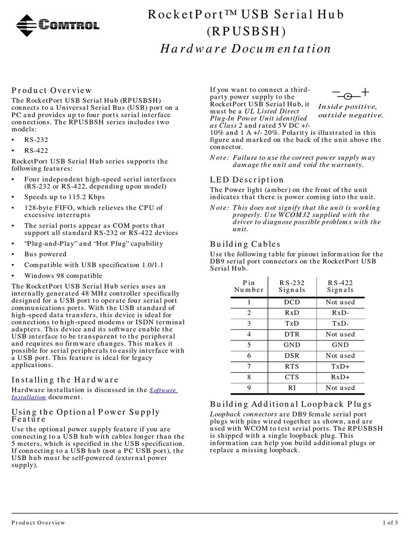
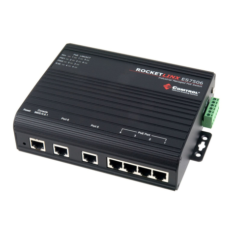
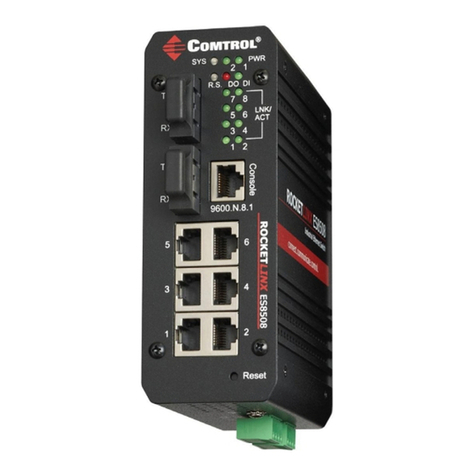
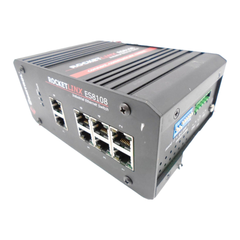
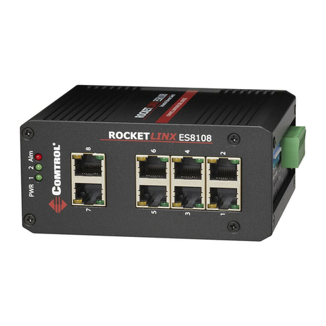
The RocketLinx ES8108 and ES8108F series of industrial Ethernet switches conform to
IEE802.3 and 802.3u standards. This series includes the following models:
• ES8108 supports eight 10/100BASE-TX ports
• ES8108F-M (Multi-Mode) supports six 10/100BASE-TX and two 100BASE-FX fiber ports
• ES8108F-S (Single-Mode) supports six 10/100BASE-TX and two 100BASE-FX fiber ports
The ES8108/ES8108F feature an IP31 rated compact metal housing for operation in harsh
environments. The series also features an alarm relay output to notify users of a port link or
power failure that can be enabled or disabled using the 9-pin DIP switch. The ES8108/8108F
can be powered using a wide input power range of 10-60VDC using the 6-pin terminal block.
See the Comtrol website for complete product specifications.
Wiring the Power Inputs
The ES8108/ES8108F provides:
• Power redundancy and reverse polarity protection (PW1/PW2). If both power inputs are
connected, the ES8108/ES8108F is powered from the highest connected voltage.
• Positive or negative power source. If using redundant power supplies, they must be in
the same mode.
• An alarm if PW1 or PW2 are no longer receiving power.
Use this procedure to wire the power:
1. Insert the positive and negative wires into the + and - contacts on the PW1 or PW2 on the
terminal block connector.
2. Tighten the wire-clamp screws to prevent the wires from being loosened.
Note: Power should be disconnected from the power supply before connecting it to the
switch. Otherwise, your screwdriver blade can inadvertently short your terminal
connections to the grounded enclosure.
PW1 Alm PW2
Alarm Control
port 1~8 power
Earth Ground
Screw
Earth Ground
Warning: Do not connect to AC line – Neutral
Connecting to the Network
Connecting the Ethernet Ports
Connect one end of an Ethernet cable into the Ethernet port of the ES8108/ES8108F and the
other end to the attached device. All Ethernet ports support auto MDI/MDIX functionality.
Always make sure that the cables between the switches and attached devices (for example,
switch, hub, or workstation) are no more than 100 meters (328 feet). The cable must meet
EIA/TIA-568 100-ohm specifications:
• 10BASE-T: 2-pair UTP/STP Category 3, 4, 5, or 5e
• 100BASE-TX: 2-pair UTP/STP Category 5 or 5e
Connecting the Fiber Ports (ES8108F)
Connect the fiber port to another Fiber Ethernet
device using the following diagram.
An improper connection will cause the fiber port
not to work properly. The fiber port is a standard
or square connector (SC).
Setting the DIP Switch
1 to 8
(Port)
9
(Power)
Switch Status Description
On Enables the port link down alarm for the corresponding port.
On Enables the power failure alarm.
Off Disables the port link down alarm for the corresponding port.
Off Disables the power failure alarm.
Wiring the Alarm Relay Output
The alarm relay output contacts are in the middle of the terminal block connector. By inserting
the wires and setting the DIP switch of the respective PortAlarm to “ON”, the alarm relay
output detects any port failures and forms a short circuit. The alarm relay output is “Normal
Open.” The alarm relay output closes if there is a port or power failure.
Maximum 0.5A/24VDC
PW1 Alm PW2
Alarm Control
port 1~8 power
Alarm
System
Extra Power
System
This is a Class 1 Laser/LED product.
Don't stare into the Laser/LED Beam.
ATTENTION
!
Mounting the Switch
Mount the ES8108/ES8108F on the DIN rail using the DIN rail clip that is attached to the rear
of the unit.
3 TD+
6 TD- 3 RD+
6 RD-
Switch Router or PC
1 RD+
2 RD- 1 TD+
2 TD-
Straight-Through Cabling Schematic
3 TD+
6 TD- 3 TD+
6 TD-
Switch Switch
1 RD+
2 RD- 1 RD+
2 RD-
Crossover Cabling Schematic
DC Power Output
Power Supply
10-60VDC
(UL Listed)
10-60VDC V-
V+
L
AC Power Input
N
Verify the Power Input requirements
on the product label.
V-
V+
Power Supply
10-60VDC
(UL Listed)
L
AC Power Input
N
DC Power Output
10-60VDC
12-24AWG
12-24AWG
Dry Relay
Output
PWR 1 PWR 2
