Memorex MVR4042 User manual

SERVICE MANUAL
MVR4042
Design and specifications are subject to change without notice.
VIDEO CASSETTE RECORDER
ORIGINAL
MFR'S VERSION A

SERVICING NOTICES ON CHECKING
As for the places which need special attentions,
they are indicated with the labels or seals on the
cabinet, chassis and parts. Make sure to keep the
indications and notices in the operation manual.
PERFORM A SAFETY CHECK AFTER
SERVICING
4.
Confirm that the screws, parts and wiring which
were removed in order to service are put in the
original positions, or whether there are the
portions which are deteriorated around the
serviced places serviced or not. Check the
insulation between the antenna terminal or
external metal and the AC cord plug blades.
And be sure the safety of that.
2. USE THE DESIGNATED PARTS
The parts in this equipment have the specific
characters of incombustibility and withstand
voltage for safety. Therefore, the part which is
replaced should be used the part which has
the same character.
Especially as to the important parts for safety
which is indicated in the circuit diagram or the
table of parts as a mark, the designated
parts must be used.
1. KEEP THE NOTICES 3. PUT PARTS AND WIRES IN THE
ORIGINAL POSITION AFTER
ASSEMBLING OR WIRING
There are parts which use the insulation
material such as a tube or tape for safety, or
which are assembled in the condition that
these do not contact with the printed board.
The inside wiring is designed not to get closer
to the pyrogenic parts and high voltage parts.
Therefore, put these parts in the original
positions.
!
A1-1
Please include the following informations when you order parts. (Particularly the VERSION LETTER.)
1. MODEL NUMBER and VERSION LETTER
The MODEL NUMBER can be found on the back of each product and the VERSION LETTER can be
found at the end of the SERIAL NUMBER.
2. PART NO. and DESCRIPTION
You can find it in your SERVICE MANUAL.
HOWTO ORDER PARTS
1.
2.
3.
4.
5.
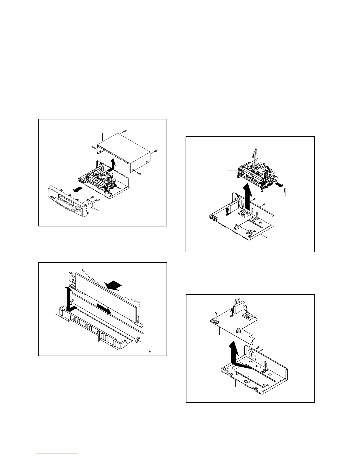
Remove the Top Cabinet and Front Cabinet.
(Refer to item 1 of the DISASSEMBLY INSTRUCTIONS.)
Remove the screw 1of the Deck Chassis and remove the Loading Motor.
Rotate the Pinch Roller Cam in the direction of the arrow by hand to slacken the Video Tape.
Rotate the Clutch Ass'y either of the directions to wind the Video Tape in the Cassette Case.
Repeat the above step 3~4. Then take out the Video Cassette from the Deck Chassis. Be careful not to
scratch on the tape.
TAPE REMOVAL METHOD AT NO POWER SUPPLY
Pinch Roller Cam
Main Cam Clutch Ass'y
Main Chassis (Front Side)
Loading Motor
Screw 1
Capstan DD Unit

CONTENTS
A1-1
A1-1
A1-1
A2-1
A3-1~A3-4
B1-1
B2-1~B2-6
B3-1, B3-2
C1-1, C1-2
C2-1
C3-1
D1-1
D1-1
D2-1~D2-4
D3-1, D3-2
E-1, E-2
E-3, E-4
E-5, E-6
E-7, E-8
E-9, E-10
F-1, F-2
F-3, F-4
G-1, G-2
G-3, G-4
G-5, G-6
G-7, G-8
G-9, G-10
G-11, G-12
G-13, G14
H-1
I1-1
I2-1, I2-2
J1-1
J2-1
J3-1
A2-1
SERVICING NOTICES ON CHECKING.....................................................................................
HOW TO ORDER PARTS ..........................................................................................................
TAPE REMOVAL METHOD AT NO POWER SUPPLY ............................................................
CONTENTS .................................................................................................................................
GENERAL SPECIFICATIONS....................................................................................................
DISASSEMBLY INSTRUCTIONS
1. REMOVAL OF MECHANICAL PARTS AND P. C. BOARDS............................................
2. REMOVAL OF VCR DECK PARTS ...................................................................................
3. REMOVAL AND INSTALLATION OF FLAT PACKAGE IC...............................................
KEY TO ABBREVIATIONS ........................................................................................................
SERVICE MODE LIST ................................................................................................................
PREVENTIVE CHECKS AND SERVICE INTERVALS..............................................................
SERVICING FIXTURES AND TOOLS .......................................................................................
PREPARATION FOR SERVICING.............................................................................................
MECHANICAL ADJUSTMENTS ................................................................................................
ELECTRICAL ADJUSTMENTS..................................................................................................
BLOCK DIAGRAMS
Y/C/AUDIO/CCD/HEAD AMP .................................................................................................
SYSTEM CONTROL/SERVO..................................................................................................
TUNER.....................................................................................................................................
HI-FI/DEMODULATOR ...........................................................................................................
OPERATION/POWER.............................................................................................................
PRINTED CIRCUIT BOARDS
SYSCON/OPERATION/BOT...................................................................................................
SYSCON..................................................................................................................................
SCHEMATIC DIAGRAMS
Y/C/AUDIO/CCD/HEAD AMP .................................................................................................
SYSTEM CONTROL/SERVO..................................................................................................
POWER ...................................................................................................................................
OPERATION............................................................................................................................
TUNER.....................................................................................................................................
HI-FI/DEMODULATOR ...........................................................................................................
INTERCONNECTION DIAGRAM ...............................................................................................
WAVEFORMS .............................................................................................................................
MECHANICAL EXPLODED VIEW .............................................................................................
CHASSIS EXPLODED VIEWS ...................................................................................................
MECHANICAL REPLACEMENT PARTS LIST .........................................................................
CHASSIS REPLACEMENT PARTS LIST..................................................................................
ELECTRICAL REPLACEMENT PARTS LIST...........................................................................

GENERAL SPECIFICATIONS
G-1 VCR System VHS Player / Recorder
System Video System NTSC
Hi-Fi STEREO Yes
NTSC PB(PAL60Hz) -
Deck DECK OVD-7
Loading System Front
Motor 3
Heads Video Head 4Head
FM Audio Head 2Head
Normal Audio /Control Mono / Yes
Erase(Full Track Erase) Yes
Tape Rec PAL -
Speed NTSC SP / SLP
Play PAL -
NTSC SP / LP / SLP
F
as
t F
o
rw
a
r
d
/
R
e
win
d
Tim
e
(
Appr
o
x.
)
a
t +2
5C
oFF:4'50"/REW:2'30"
with Cassette T-120
Forward/Reverse NTSC or PAL-M SP / LP / SLP=3x,5x / 7x,9x / 9x,15x
Picture Search PAL or SECAM -
Frame Advance Slow Yes
Slow Speed Variable Slow 1/10
G-2 Tuning Broadcasting System US System M
System Tuner and System 1Tuner
Receive CH Destination USA(w/CATV)
Tuning System F-Synth
Input Impedance VHF/UHF 75 OHM
CH Coverage 2-69,4A,A-5~ A-1,A~I,J~ W
W+1-W+84
Intermediate Picture(FP) 45.75MHz
Frequency Sound(FS) 41.25MHz
FP-FS 4.50MHz
Preset CH No
RF Converter Output Yes
Channel 3 or 4 ch
Level/Impedance 66dBu /75ohm
Sound Selector No
Stereo/Dual TV Sound Yes (US-Stereo)
G-3 Power Power Source AC 120V, 60Hz
DC -
Power Consumption Power On(at AC) 9W at 120V 60Hz
Stand by (at AC) 1.7W at 120V 60Hz
Per Year - kWh/Year
Protector Power Fuse Yes
Dew Sensor No
G-4 Regulation Safety UL
Radiation FCC
G-5 Temperature Operation
5
o
C
- 4
0
o
C
Storage -2
0
o
C
-
60
o
C
G-6 Operating Humidity Less than 80% RH
G-7 Signal Video Signal Input Level 1 V p-p/75 ohm
Output Level 1 V p-p/75 ohm
S/N Ratio (Weighted) 50
Horizontal Resolution at SP Mode 230Line
Audio Signal Input Level -8dBm/50Kohm
Output Level -8dBm/1Kohm
S/N Ratio at SP (Weighted) 42dB
Harmonic Distortion at SP (1KHz)
T
y
pical 1.5%
Frequency Response at SP 100Hz - 10kHz
at LP 100Hz - 6kHz
at SLP 100Hz - 4kHz
Hi-Fi Audio Signal Dynamic Range : More than 90dB
Frequency Response 20Hz ~20kHz
Wow And Flutter : Less than 0.01 %Wrms
Channel Separation : More than 60 dB
Harmonic Distortion : Less than 0.01
G-8 On Screen Menu Yes
Display Menu Type Character
Timer Rec Set Yes
Auto Repeat On/Off Yes
SAP On/Off Yes
CH Setup Yes
TV/CATV Yes
Auto CH Memory Yes
Add/Delete Yes
System Setup Yes
A3-1

GENERAL SPECIFICATIONS
Clock Set Yes (Calendar 12H)
Language Yes
No Noise Back Ground Yes
Auto Clock No
Standard Time No
Daylight Saving Time No
G-CODE(or SHOWVIEW or PLUSCODE)No. Entry No
Stereo,Audio Output,SAP Yes
Play/Stop/FF/Rew/Rec/OTR(ITR)/T-Rec/Pause/Eject/Tape In
(S
y
mbol Mark) Yes
CH/AV(LINE) Yes
Clock Yes
Repeat Yes
Tape Counter Yes
Index No
Tape Speed Yes
ATR / Manual Tracking Yes
Zero Return No
Hi-Fi Yes
G-9 OSD Language English French Spanish
OSD Language Setting English
G-10 Clock,Timer Calendar 1990/1/1 ~ 2081/12/31
and Timer Timer Events 8 prog/1 month
Back-up One Touch Recording Max Time 6 Hours
OTPB Valid Time No
Timer Back-up (at Power Off Mode) 5 sec.
G-11 Display Indicator No
Indicator Type --
Clock/Counter,CH,Timer Rec, Play, REC --
OTR,FF(Cue),Rew(Rev),Stop,ATR --
VCR --
PM --
RF Output CH --
G-12 Remote Unit RC-EA
Control Glow in Dark Remocon No
Format type NEC
Custom Code 80-7BH
Power Source Voltage(D.C) 3V
UM size x pcs UM-4 x 2 pcs
Total Keys 33 Keys
Keys Power Yes
1 Yes
2 Yes
3 Yes
4 Yes
5 Yes
6 Yes
7 Yes
8 Yes
9 Yes
0 Yes
CH Up Yes
CH Down Yes
Input Select Yes
Play Yes
F.Fwd Yes
Rew Yes
Pause/Still Yes
Stop Yes
Rec/OTR Yes
Counter Reset Yes
Speed Yes
Timer Rec Yes
Slow Yes
Auto Tracking Yes
Set/Tracking+ Yes
Set/ Tracking - Yes
Menu Yes
Enter Yes
Cancel Yes
Call Yes
TV/VCR Yes
Audio Select Yes
Clock/Counter No
Zero Return No
G-13 Features Auto Head Cleaning Yes
Auto Tracking Yes
A3-2

GENERAL SPECIFICATIONS
Index Search No
HQ (VHS Standard High Quality) Yes
Auto Power On, Auto Play, Auto Rewind, Auto Eject Yes
Auto Power Off Yes
Forward/Reverse Picture Search Yes
VIDEO PLUS+ (SHOWVIEW,G-CODE) No
One Touch Play Back No
Auto CH Memory Yes
SQPB No
CATV Yes
Energy Star Yes
MTS (SAP) Yes
Auto Clock Set No
CM Skip (30sec x 6 Times) No
G-14 Accessories Owner's Manual Language English / Spanish
w/Guarantee Card No
Buyer Model No. MVR4042
Remote Control Unit Yes
Dew Caution Sheet No
Video Cassette Tape No
Battery No
UM size x pcs -
-
Safety Tip No
Toll Free Insert Sheet No
Quick Set-Up Sheet No
Information Sheet (Buyer Supply) No
75 Ohm Coaxial Cable Yes(single shield)
Rod Antenna No
Poles
Terminal
Loop Antenna No
Terminal
U/V Mixer No
DC Car Cord (Center+) No
Guarantee Card Yes
Warning Sheet No
Circuit Diagram No
Antenna Change Plug No
Service Station List No
Important Safeguard No
Dew/AHC Caution Sheet No
AC Plug Adapter No
Quick Set-up Sheet No
AC Cord No
AV Cord No
Registration Card No
PTB Sheet No
300 ohm to 75 ohm Antenna Adapter No
G-15 Interface Switch Front Power Yes
Play Yes
Pause/Still No
System Select No
One Touch Playback No
Channel Up Yes
Channel Down Yes
F.FWD/Cue Yes
Eject/Stop Yes
Main Power SW No
Volume Up No
Volume Down No
Rew/Rev Yes
Rec/OTR(ITR) Yes
Rear RF Output SW No
Indicator Power Yes (Red)
Stand by No
Repeat No
TV/VCR Yes (Red)
Rec Yes (Red)
T-Rec Yes (Red)
Tape In No
Terminals Front Video Input RCA x 1 (Yellow)
Audio Input RCA x 2 (Stereo, White/Red)
Other Terminal No
Rear Video Input No
Audio Input No
Video Output RCA x 1 (Yellow)
A3-3

GENERAL SPECIFICATIONS
Audio Output RCA x 2 (Stereo, White/Red)
Euro Scart No
DC Jack 12V (Center +) No
VHF/UHF Antenna Input F Type
AC Inlet No
G-16 Set Size Approx. W x D x H (mm) 360 ~226 ~95
G-17 Weight Net (Approx.) 3.2kg(7.1lbs)
Gross (Approx.) 3.8kg(8.4lbs)
G-18 Carton Master Carton No
Content -
Material -
Dimensions W x D x H (mm) -
Description of Origin -
Gift Box Yes
Material Single/White
Dimensions W x D x H (mm) 420x291x160
Design As Per BUYER 's
Description of Origin Yes
Drop Test Natural Dropping At 1Corner / 3Edges / 6Surfaces
Height (cm) 80
Container Stuffing(40' container) 3,136 Sets
G-19 Material Cabinet Front PS 94V2 / DECABROM
PCB Non-Halogen Demand No
Eyelet Demand No
A3-4

DISASSEMBLY INSTRUCTIONS
1.REMOVAL OF MECHANICAL PARTS
AND P.C. BOARDS
1-1: TOP CABINET, FRONT CABINET AND
OPERATION PCB (Refer to Fig. 1-1)
1.
2.
3.
4.
5.
6.
Remove the 4 screws (1).
Remove the Top Cabinet in the direction of arrow (A).
Disconnect the following connector: (CP651).
Unlock the 7 supports (2).
Remove the Front Cabinet in the direction of arrow (B).
Remove the 3 screws (3) and remove the Operation PCB.
1-2: FLAP (Refer to Fig. 1-2)
1.
2.
Open Flap to 90°and flex in direction of arrow (A), at
the same time slide in direction of arrow (B).
Then lift in direction of arrow (C).
Fig. 1-2
B1-1
Fig. 1-1
(A)
(C)
(B)
Flap
Upper side
Bottom side
1-4: SYSCON PCB (Refer to Fig. 1-4)
1.
2.
3.
4.
Remove the screw (1).
Remove the screw (2).
Remove the 2 screws (3).
Remove the Syscon PCB in the direction of arrow.
Fig. 1-4
Syscon PCB
Bottom Plate
(3)
(1)(2)
(3)
1-3:DECKCHASSIS(RefertoFig.1-3)
NOTE
Do not remove the cable at the FE Head section. The FE
Head may be damaged if you remove the cable by force.
1.
2.
3.
4.
5.
6.
7.
8.
Remove the screw (1).
Remove the FE Head.
Remove the screw (2).
Remove the 2 screws (3).
Unlock the 2 supports (4).
Remove the BOT PCB in the direction of arrow (A).
Disconnect the following connectors:
(CP1001, CP4001, CP4002 and CP4003).
Remove the Deck Chassis in the direction of arrow (B).
Deck Chassis
Fig. 1-3
Bottom Plate
(2)
(1)
(3) (3)
FE Head
BOT PCB
(B)
(A)
(4) (4)
(B)
(A)
Top Cabinet
Operation PCB
Front Cabinet
(1)
(1)
(1)
(1)
(3)
(3) (3)
(2)
(2) (2)
(2)(2)
(2)
(2)

DISASSEMBLY INSTRUCTIONS
B2-1
2. REMOVAL OF VCR DECK PARTS
2-1: TOP BRACKET (Refer to Fig. 2-1)
Extend the 2 supports (1).
Slide the 2 supports (2) and remove the Top Bracket.
1.
2.
2-2: CASSETTE HOLDER ASS'Y (Refer to Fig. 2-2)
Move the Cassette Holder Ass'y to the front side.
Push the Locker R to remove the Cassette Side R.
Remove the Cassette Side L.
1.
2.
3.
Fig. 2-1
Main Chassis
Main Chassis
Top Bracket
Top Bracket
Main Chassis
Main Chassis
Cassette Side L
Cassette Side R Locker R
Fig. 2-2
2-3: CASSETTE SIDE L/R (Refer to Fig. 2-3-A)
Remove the Locker Spring.
Unlock the 4 supports (1) and then remove the
Cassette Side L/R.
Unlock the support (2) and then remove the Locker R.
1.
2.
3.
Link Ass'y
NOTE
1.
2.
In case of the Locker R installation, check if the one
position of Fig.2-3-B is correctly locked.
When you install the Cassette Side R, be sure to move
the Locker R after installing.
2-4: LINK UNIT (Refer to Fig. 2-4)
Set the Link Unit to the Eject position.
Unlock the support (1).
Remove the (A) side of the Link Unit first, then remove
the (B) side.
1.
2.
3.
Fig. 2-4
2-5: LINK LEVER/FLAP LEVER/SENSOR
Unlock the support (1).
Remove the Sensor Cover R.
Extend the support (1).
Remove the Link Lever.
Remove the Flap Lever.
1.
2.
3.
4.
5.
Fig. 2-3-A
Cassette Side L
Cassette Side R
Locker R
Cassette Holder
Locker Spring
Fig. 2-3-B
Check if this
position is locked.
(A)
Link Unit
Main Chassis
Link Unit
(B)
Main Chassis
Cassette Side R
Locker R
(1)
NOTE
1. After the installation of the Top Bracket, bend the
support (1) so that the Top Bracket is fixed.
(1)
(2)
(2)
(2)
(1)
(1)
(1)
(1)
(1)
Fig. 2-5
(2)
Link Lever
Flap Lever
Sensor Cover R
COVER R (Refer to Fig. 2-5)

DISASSEMBLY INSTRUCTIONS
B2-2
2-6: LOADING MOTOR/WORM (Refer to Fig. 2-6-A)
Remove the screw (1).
Remove the Loading Motor.
Remove the Worm.
1.
2.
3.
Fig. 2-6-A
• Screw Torque: 3 ±0.5kgf•cm
Loading Motor
(1)
Main Chassis
Worm
2-7: TENSION ASS'Y (Refer to Fig. 2-7-B)
Turn the Pinch Roller Cam clockwise so that the
Tension Holder hook is set to the position of Fig. 2-7-A
to move the Tension Arm Ass'y.
Remove the Tension Spring.
Unlock the 2 supports (1) and remove the Tension
Band.
Unlock the support (2) and remove the Tension Arm
Ass'y.
Unlock the support (3) and remove the Tension
Connect.
Float the hook (4) and turn it clockwise then remove the
Tension Holder.
1.
2.
3.
4.
5.
6.
NOTE
1.
2.
3.
In case of the Worm installation, check if the value of
the Fig. 2-6-B is correct.
In case of the Loading Motor installation, hook the wire
on the Cassette Opener as shown Fig. 2-6-C.
When installing the wires between Capstan DD Unit
and Loading Motor, connect them correctly as shown
Fig. 2-6-D.
Loading Motor Capstan DD Unit
-
+
L2
L1
Pink
Fig. 2-6-D
White
Fig. 2-7-A
Tension Arm Ass'y
Fig. 2-7-B
Fig. 2-7-D
Tension Band
Tension Spring
(1)
(2)
(4)
Tension Band
Tension Arm Ass'y
(3)
(1)
Tension Holder
Tension Connect
NOTE
1.
2.
3.
In case of the Tension Band installation, note the
direction of the installation. (Refer to Fig. 2-7-C)
In case of the Tension Band installation, install correctly
as Fig. 2-7-D.
In case of the Tension Connect installation, install as
the circled section of Fig. 2-7-E.
Tension Band
Tension Connect
Tension Connect
[OK]
[NG]
Fig. 2-7-E
Tension Connect
Main Chassis
Fig. 2-7-C
Tension Band
Tension Connect
Fig. 2-6-B
19.2 ±0.1mm
Safety surface for pressing
of the insert.
Fig. 2-6-C
Loading Motor
Cassette Opener

DISASSEMBLY INSTRUCTIONS
B2-3
Fig. 2-8-B
T Brake Band
NOTE
1. In case of the T Brake Band installation, install correctly
as Fig. 2-8-B.
T Brake Arm
[OK]
[NG] T Brake Band
T Brake Arm
2-9: S REEL/T REEL/IDLER ARM ASS'Y/IDLER GEAR
(Refer to Fig. 2-9-A)
Remove the S Reel and T Reel.
Remove the 2 Polyslider Washers (1).
Remove the Idler Arm Ass'y and Idler Gear.
1.
2.
3.
NOTE
Take care not to damage the gears of the S Reel and T
Reel.
The Polyslider Washer may be remained on the back of
the reel.
Take care not to damage the shaft.
Do not touch the section "A" of S Reel and T Reel. (Use
gloves.) (Refer to Fig. 2-9-A) Do not adhere the stains
on it.
When you install the reel, clean the shaft and grease it
(FG-84M). (If you do not grease, noise may be heard in
FF/REW mode.)
After installing the reel, adjust the height of the reel.
(Refer to MECHANICAL ADJUSTMENT)
1.
2.
3.
4.
5.
6.
Fig. 2-9-A
NOTE
1.
2.
In case of the S Reel and T Reel installation, check if the
correct parts are installed. (Refer to Fig. 2-9-B)
In case of the Idler Arm Ass'y installation, install correctly
as Fig. 2-9-C, And also set it so that the section "B" of
Fig. 2-9-A is placed under the Main Chassis tab.
2-8: T BRAKE ARM/T BRAKE BAND (Refer to Fig. 2-8-A)
Remove the T Brake Spring.
Turn the T Brake Arm clockwise and bend the hook
section to remove it.
Unlock the 2 supports (1) and remove the T Brake
Band.
1.
2.
3.
T Brake Band
Hook section
T Brake Spring
T Brake Arm
Fig. 2-8-A
(1)
(1)
S Reel
(A) T Reel
(A)
Idler Arm Ass'y
Idler Gear
(1)
(1)
Fig. 2-9-B
Big Hole
(S Reel) Small Hole
(T Reel)
Fig. 2-9-C
Idler Arm Ass'y
[OK]
[NG]
Clutch Gear
Idler Arm Ass'y
Clutch Gear
(B)

DISASSEMBLY INSTRUCTIONS
B2-4
2-10: CASSETTE OPENER/PINCH ROLLER BLOCK/P5
ARM ASS'Y (Refer to Fig. 2-10-A)
Unlock the support (1) and remove the Cassette
Opener.
Remove the Pinch Roller Block and P5 Arm Ass'y.
1.
2.
Fig. 2-10-A
Cassette Opener
P5 Arm Ass'y
Pinch Roller Block
Main Chassis
(1)
NOTE
Do not touch the Pinch Roller. (Use gloves.)
In case of the Pinch Roller Block and the Pinch Roller
Cam installation, install correctly as Fig. 2-10-B.
1.
2.
Fig. 2-10-B
Can be seen the hole of the
Main Cam.
Can be seen the hole of
the Pinch Roller Cam.
P5 Arm Ass'y
Pinch Roller Block
2-11: A/C HEAD (Refer to Fig. 2-11-A)
Remove the screw (1).
Remove the A/C Head Base.
Remove the 3 screws (2).
Remove the A/C Head and A/C Head Spring.
1.
2.
3.
4.
NOTE
Do not touch the A/C Head. (Use gloves.)
When you install the A/C Head Spring, install as shown
in Fig. 2-11-B.
When you install the A/C Head, tighten the screw (1) first,
then tighten the screw (2), finally tighten the screw (3).
1.
2.
3.
A/C Head
A/C Head Spring
(3)
(1)
(2)
A/C Head Base
Fig. 2-11-A
(2)
(1)
(2)
(2)
• Screw Torque: 5 ±0.5kgf•cm
Spring Position Fig. 2-11-B
2-12: FE HEAD (RECORDER ONLY) (Refer to Fig. 2-12)
Remove the screw (1).
Remove the FE Head.
FE Head
• Screw Torque: 5 ±0.5kgf•cm
• The FE Head is not installed on the Video Cassette Player. Fig. 2-12
(1)
1.
2.
2-13: AHC ASS'Y/CYLINDER UNIT ASS'Y
(Refer to Fig. 2-13)
Unlock the support (1) and remove the AHC Ass'y.
Disconnect the following connector: (CD2001)
Remove the 3 screws (2).
Remove the Cylinder Unit Ass'y.
1.
2.
3.
4.
Fig. 2-13
When you install the Cylinder Unit Ass'y, tighten the
screws from (1) to (3) in order while pulling the Ass'y
toward the left front direction.
NOTE
1.
• Screw Torque: 3 ±0.5kgf•cm
Cylinder Unit Ass'y
(1)
(3)
(2)
(2) (2) (2)
(1)
AHC Ass'y

DISASSEMBLY INSTRUCTIONS
B2-5
Fig. 2-15-A
NOTE
In case of the Pinch Roller Cam and Main Cam
installation, install them as the circled section of Fig. 2-
15-B so that the each markers are met. (Refer to Fig.
2-15-B)
2-15:
Remove the E-Ring (1), then remove the Main Cam.
Remove the E-Ring (2), then remove the Pinch Roller
Cam and Joint Gear.
1.
2.
MAIN CAM/PINCH ROLLER CAM/JOINT GEAR
(Refer to Fig. 2-15-A)
Main Cam
Pinch Roller Cam
Joint Gear
1.
Pinch Roller Cam
Main Cam
Marker
2-16: LOADING GEAR S/T UNIT (Refer to Fig. 2-16-A)
1.
2.
Remove the E-Ring (1) and remove the Main Loading
Gear.
Remove the Main Rod, Tension Lever, Loading Arm S
Unit and Loading Arm T Unit.
Main Rod Main Loading Gear
Loading Arm T Unit
Loading Arm S Unit
Fig. 2-16-A
(1)
(1)
(2)
2-14: CAPSTAN DD UNIT (Refer to Fig. 2-14-A)
Remove the Capstan Belt.
Remove the 3 screws (1).
Remove the Capstan DD Unit.
1.
2.
3.
Fig. 2-14-A
• Screw Torque: 4 ±0.5kgf•cm
Capstan DD Unit
Capstan Belt
(1)
(1)
(1)
In case of the Capstan DD Unit installation, apply the
silicon bond (TSE3843-W) on the position Fig. 2-14-B
correctly. (If no silicon bond applied, abnormal nosie
will be heard on the deck operation.)
(Refer to Fig. 2-14-B, C)
NOTE
1.
Fig. 2-15-B
Fig. 2-14-B
Fig. 2-14-C
Tension Lever
Main Chassis
Silicon Bond
Capstan DD Unit
Applied position of
silicon bond
Be careful not to apply the silicon
bond to the Pinch Roller.

DISASSEMBLY INSTRUCTIONS
B2-6
2-18:
Remove the P4 Cap.
Unlock the support (1) and remove the Cassette Guide
Post.
Remove the Inclined Base S/T Unit.
Remove the screw (2).
Remove the LED Reflector.
1.
2.
3.
4.
5.
Fig. 2-18-A
CASSETTE GUIDE POST/INCLINED BASE S/T
UNIT/P4 CAP (Refer to Fig. 2-18-A)
P4 Cap
Cassette Guide Post
Inclined Base T
Unit
Inclined Base S
Unit
NOTE
Do not touch the roller of Guide Roller.
In case of the P4 Cap installation, install it with parallel
for "A" and "B" of Fig. 2-18-B.
In case of the Cassette Guide Post installation, install
correctly as the circled section of Fig. 2-18-C.
1.
2.
3.
"A"
[OK]
[NG]
"B"
P4 Cap Cassette Opener
Fig. 2-18-B
Fig. 2-18-C
Cassette Guide Post
Cassette Guide Post
2-17:
Remove the Polyslider Washer (1).
Remove the Clutch Ass'y and Ring Spring.
Remove the Clutch Lever.
Remove the Coupling Gear, Coupling Spring and
Clutch Gear.
1.
2.
3.
4.
Fig. 2-17-A
NOTE
1. When you install the Loading Arm S Unit, Loading Arm
T Unit and Main Loading Gear, align each marker.
(Refer to Fig. 2-16-B)
Fig. 2-16-B
Loading Arm T Unit
Main Loading Gear
Marker
Marker
Loading Arm S Unit
CLUTCH ASS'Y/RING SPRING/CLUTCH LEVER/CLUTCH
GEAR (Refer to Fig. 2-17-A)
NOTE
In case of the Clutch Ass'y installation, install it with
inserting the spring of the Clutch Ass'y into the dent of
the Coupling Gear. (Refer to Fig. 2-17-B)
1.
Clutch Ass'y
Fig. 2-17-B
Coupling Gear
(1)
Clutch Ass'y
Coupling Gear Clutch Lever
Ring Spring
Coupling Spring
Clutch Gear
(1)
LED Reflector
• Screw Torque: 5 ±0.5kgf•cm

Masking Tape
(Cotton Tape)
DISASSEMBLY INSTRUCTIONS
3.
REMOVAL
IC
Put the Masking Tape (cotton tape) around the Flat
Package IC to protect other parts from any damage.
(Refer to Fig. 3-1.)
1.
Fig. 3-1
NOTE
REMOVAL AND INSTALLATION OF
FLAT PACKAGE IC
Some ICs on the PCB are affixed with glue, so be
careful not to break or damage the foil of each IC
leads or solder lands under the IC when removing it.
NOTE
Masking is carried out on all the parts located within
10 mm distance from IC leads.
Blower type IC
desoldering machine
IC
Heat the IC leads using a blower type IC desoldering
machine. (Refer to Fig. 3-2.)
2.
Fig. 3-2
NOTE
Do not add the rotating and the back and forth
directions force on the IC, until IC can move back and
forth easily after desoldering the IC leads completely.
When IC starts moving back and forth easily after
desoldering completely, pickup the corner of the IC using
a tweezers and remove the IC by moving with the IC
desoldering machine. (Refer to Fig. 3-3.)
3.
Blower type IC
desoldering
machine
IC Fig. 3-3
Tweezers
Peel off the Masking Tape.4. Absorb the solder left on the pattern using the Braided
Shield Wire. (Refer to Fig. 3-4.)
5.
NOTE
Do not move the Braided Shield Wire in the vertical
direction towards the IC pattern.
Braided Shield Wire
Soldering Iron
Fig. 3-4
IC pattern
B3-1

DISASSEMBLY INSTRUCTIONS
Supply soldering
from upper position
to lower position
IC
Supply the solder from the upper position of IC leads
sliding to the lower position of the IC leads.
(Refer to Fig. 3-6.)
2.
Fig. 3-6
Soldering IronSolder
IC
Absorb the solder left on the lead using the Braided
Shield Wire. (Refer to Fig. 3-7.)
3.
Fig. 3-7
Soldering Iron
Braided Shield Wire
NOTE
Do not absorb the solder to excess.
IC
When bridge-soldering between terminals and/or the
soldering amount are not enough, resolder using a Thin-
tip Soldering Iron. (Refer to Fig. 3-8.)
4.
Fig. 3-8
Thin-tip Soldering Iron
NOTE
When the IC leads are bent during soldering and/or
repairing, do not repair the bending of leads. If the
bending of leads are repaired, the pattern may be
damaged. So, be always sure to replace the IC in this
case.
Finally, confirm the soldering status on four sides of the
IC using a magnifying glass.
Confirm that no abnormality is found on the soldering
position and installation position of the parts around the
IC. If some abnormality is found, correct by resoldering.
5.
Solder temporarily
Soldering Iron
INSTALLATION
Take care of the polarity of new IC and then install the
new IC fitting on the printed circuit pattern. Then solder
each lead on the diagonal positions of IC temporarily.
(Refer to Fig. 3-5.)
1.
Fig. 3-5
Solder temporarily
B3-2

KEY TO ABBREVIATIONS
A
B
C
D
E
F
G
H
A/C
ACC
AE
AFC
AFT
AFT DET
AGC
AMP
ANT
A.PB
APC
ASS'Y
AT
AUTO
A/V
BGP
BOT
BPF
BRAKE SOL
BUFF
B/W
C
CASE
CAP
CARR
CH
CLK
CLOCK (SY-SE)
COMB
CONV
CPM
CTL
CYL
CYL-M
CYL SENS
DATA (SY-CE)
dB
DC
DD Unit
DEMOD
DET
DEV
E
EF
EMPH
ENC
ENV
EOT
EQ
EXT
F
FBC
FE
FF
FG
FL SW
FM
FSC
FWD
GEN
GND
H.P.F
:
:
:
:
:
:
:
:
:
:
:
:
:
:
:
:
:
:
:
:
:
:
:
:
:
:
:
:
:
:
:
:
:
:
:
:
:
:
:
:
:
:
:
:
:
:
:
:
:
:
:
:
:
:
:
:
:
:
:
:
:
:
Audio/Control
Automatic Color Control
Audio Erase
Automatic Frequency Control
Automatic Fine Tuning
Automatic Fine Tuning Detect
Automatic Gain Control
Amplifier
Antenna
Audio Playback
Automatic Phase Control
Assembly
All Time
Automatic
Audio/Video
Burst Gate Pulse
Beginning of Tape
Bandpass Filter
Brake Solenoid
Buffer
Black and White
Capacitance, Collector
Cassette
Capstan
Carrier
Channel
Clock
Clock (Syscon to Servo)
Combination, Comb Filter
Converter
Capstan Motor
Control
Cylinder
Cylinder-Motor
Cylinder-Sensor
Data (Syscon to Servo)
Decibel
Direct Current
Direct Drive Motor Unit
Demodulator
Detector
Deviation
Emitter
Emitter Follower
Emphasis
Encoder
Envelope
End of Tape
Equalizer
External
Fuse
Feed Back Clamp
Full Erase
Fast Forward, Flipflop
Frequency Generator
Front Loading Switch
Frequency Modulation
Frequency Sub Carrier
Forward
Generator
Ground
High Pass Filter
I
K
L
M
N
O
P
R
S
H.SW
Hz
IC
IF
IND
INV
KIL
L
LED
LIMIT AMP
LM, LDM
LP
L.P.F
LUMI.
M
MAX
MINI
MIX
MM
MOD
MPX
MS SW
NC
NR
OSC
OPE
PB
PB CTL
PB-C
PB-Y
PCB
P. CON
PD
PG
P-P
R
REC
REC-C
REC-Y
REEL BRK
REEL S
REF
REG
REW
REV, RVS
RF
RMC
RY
S. CLK
S. COM
S. DATA
SEG
SEL
SENS
SER
SI
SIF
SO
SOL
SP
STB
SW
:
:
:
:
:
:
:
:
:
:
:
:
:
:
:
:
:
:
:
:
:
:
:
:
:
:
:
:
:
:
:
:
:
:
:
:
:
:
:
:
:
:
:
:
:
:
:
:
:
:
:
:
:
:
:
:
:
:
:
:
:
:
Head Switch
Hertz
Integrated Circuit
Intermediate Frequency
Indicator
Inverter
Killer
Left
Light Emitting Diode
Limiter Amplifier
Loading Motor
Long Play
Low Pass Filter
Luminance
Motor
Maximum
Minimum
Mixer, mixing
Monostable Multivibrator
Modulator, Modulation
Multiplexer, Multiplex
Mecha State Switch
Non Connection
Noise Reduction
Oscillator
Operation
Playback
Playback Control
Playback-Chrominance
Playback-Luminance
Printed Circuit Board
Power Control
Phase Detector
Pulse Generator
Peak-to Peak
Right
Recording
Recording-Chrominance
Recording-Luminance
Reel Brake
Reel Sensor
Reference
Regulated, Regulator
Rewind
Reverse
Radio Frequency
Remote Control
Relay
Serial Clock
Sensor Common
Serial Data
Segment
Select, Selector
Sensor
Search Mode
Serial Input
Sound Intermediate Frequency
Serial Output
Solenoid
Standard Play
Serial Strobe
Switch
C1-1

KEY TO ABBREVIATIONS
S
T
U
V
X
Y
SYNC
SYNC SEP
TR
TRAC
TRICK PB
TP
UNREG
V
VCO
VIF
VP
V.PB
VR
V.REC
VSF
VSR
VSS
V-SYNC
VT
X'TAL
Y/C
:
:
:
:
:
:
:
:
:
:
:
:
:
:
:
:
:
:
:
:
:
Synchronization
Sync Separator, Separation
Transistor
Tracking
Trick Playback
Test Point
Unregulated
Volt
Voltage Controlled Oscillator
Video Intermediate Frequency
Vertical Pulse, Voltage Display
Video Playback
Variable Resistor
Video Recording
Visual Search Fast Forward
Visual Search Rewind
Voltage Super Source
Vertical-Synchronization
Voltage Tuning
Crystal
Luminance/Chrominance
C1-2

C2-1
SERVICE MODE LIST
This unit provided with the following SERVICE MODES so you can repair, examine and adjust easily.
Method Operations
Adjusting of the Tracking to the center position.
Refer to the "MECHANICAL ADJUSTMENT" (GUIDE ROLLER) and "ELECTRICAL
ADJUSTMENT" (PG SHIFTER).
Press the ATR button on the
remote control for more than
2 seconds during PLAY.
Make the short circuit
between the test point of
SERVICE and the GND.
The BOT, EOT and the Reel Sensor do not work and the deck can be operated
without a cassette tape.
Refer to the "PREPARATION FOR SERVICING"

C3-1
PREVENTIVE CHECKS AND SERVICE INTERVALS
The following standard table depends on environmental conditions and usage.
Parts replacing time does not mean the life span for individual parts.
Also, long term storage or misuse may cause transformation and aging of rubber parts.
The following list means standard hours, so the checking hours depends on the conditions.
Parts Name
Audio Control Head
Notes
Time 500
hours 1,000
hours 1,500
hours 2,000
hours 2,500
hours
Full Erase Head
(Recorder only)
Capstan Belt
Pinch Roller
Capstan DD Unit
Loading Motor
Tension Band
Clean those parts in
contact with the tape.
Clean the rubber, and parts
which the rubber touches.
: Clean
: Check it and if necessary, replace it.
TBrake Band
Capstan Shaft
Tape Running
Guide Post
Cylinder Unit
Replace when rolling
becomes abnormal.
Clean the Head
Clutch Ass'y
Idler Arm Ass'y
CLEANING
NOTE
After cleaning the heads with isopropyl alcohol, do not
run a tape until the heads dry completely. If the heads
are not completely dry and alcohol gets on the tape,
damage may occur.
1. AUDIO CONTROL HEAD
Clean the Audio Control Head with the cotton stick
soaked by alcohol. Clean the full erase head in the
same manner. (Refer to the figure below.)
2. TAPE RUNNING SYSTEM
When cleaning the tape transport system, use the
gauze moistened with isopropyl alcohol.
3. CYLINDER
Wrap a piece of chamois around your finger. Dip it in
isopropyl alcohol. Hold it to the cylinder head softly.
Turn the cylinder head counterclockwise to clean it (in
the direction of the arrow). (Refer to the figure below.)
NOTE
Do not exert force against the cylinder head. Do not move
the chamois upward or downward on the head.
Use the chamois one by one.
Cylinder Head
Audio Control Head
Other manuals for MVR4042
1
Table of contents
Other Memorex VCR System manuals

Memorex
Memorex MVR4042 User manual

Memorex
Memorex MVR-4040A User manual

Memorex
Memorex MVR4041 User manual

Memorex
Memorex MVR2040A C Series User manual

Memorex
Memorex MVR-4040A User manual

Memorex
Memorex MVP0028 User manual

Memorex
Memorex MVR2041 User manual

Memorex
Memorex MVT2137 User manual

Memorex
Memorex MVR4051/MVR4052 User manual

Memorex
Memorex MVR4041 User manual