Mentor radio M2115M User manual

M2115 OWNERS MANUAL
Solutions for Advancing Communications
Model M2115
Airport Ground Support Radios
VHF Voice Radio Frequency Band: (118.025-136.975 MHz)
This document supports the following models:
M2115M Mobile Receiver/Transmitter - 10 Watt
M2115B Base Station Receiver/Transmitter - 10 Watt
M2115B-25 Base Station Receiver/Transmitter - 25 Watt
M2115B-50 Base Station Receiver/Transmitter - 50 Watt

2
Phone: 216-265-2315 Fax: 216-267-2915
www.mentorradio.com (11/11)
M2115 OWNERS MANUAL
Solutions for Advancing Communications
CONTENTS
Safety Notices [1] ............................................................................................................................................ 3
Mechanical Diagrams [2]................................................................................................................................. 4
Front Panel Diagram M2115 [2.1] ................................................................................................................ 4
Rear Panel Diagrams [2.2] .......................................................................................................................... 5
Introduction [3] ................................................................................................................................................ 6
Physical Component Descriptions [4] ........................................................................................................... 6
Radio Cards [4.1] ...................................................................................................................................... 6
USB- and USB-B Ports [4.2] ...................................................................................................................... 7
Rear Panel [4.3] ........................................................................................................................................ 7
Global Positioning System (GPS) [4.4] ......................................................................................................... 7
Receiver [4.5] ........................................................................................................................................... 8
Transmitter [4.6] ....................................................................................................................................... 8
General Operation [4.6.1] ............................................................................................................................................. 8
Hot Microphone Detection [4.6.2] ................................................................................................................................. 8
Base Station PTT Operation [4.6.3].............................................................................................................................. 9
High Voltage Standing Wave Ratio (VSWR) Detection [4.6.4]..................................................................................... 9
AM Modulation Control [4.6.5] ...................................................................................................................................... 9
Front Panel Control [4.7] ............................................................................................................................ 9
Overview [4.7.1]............................................................................................................................................................ 9
5-Pin XLR Locking Microphone/Headset Connector [4.7.2]......................................................................................... 9
Power Control Button [4.7.3]......................................................................................................................................... 9
Menu Buttons [4.7.4]................................................................................................................................................... 10
Rotary Knob [4.7.5]..................................................................................................................................................... 10
Internal Speaker [4.7.6] .............................................................................................................................................. 10
VSWR [5] ........................................................................................................................................................ 10
Screen Control [6] ......................................................................................................................................... 11
Installation [7] ................................................................................................................................................ 17
Notice [7.1] ............................................................................................................................................. 17
M2115M [7.2] .......................................................................................................................................... 17
M2115B-xx [7.3] ...................................................................................................................................... 18
Global Positioning System (GPS) Module [7.4] Future feature, not currently available. ..................................... 18
Remote Control [7.5] ................................................................................................................................ 19
Planning [7.5.1] ........................................................................................................................................................... 19
Installation [7.5.2]........................................................................................................................................................ 19

3
Phone: 216-265-2315 Fax: 216-267-2915
www.mentorradio.com (11/11)
M2115 OWNERS MANUAL
Solutions for Advancing Communications
User Security Notice [8] ................................................................................................................................ 22
Maintenance [9] ............................................................................................................................................. 22
Servicing and Repair [10].............................................................................................................................. 22
Trouble Shooting and User Repair Guide [11] ............................................................................................ 23
Licensing [12] ................................................................................................................................................ 24
Limited Warranty [13].................................................................................................................................... 25
Safety Notices [1]
The following safety precautions are meant to prevent personal injury and damage to the equipment.
1.) Do not connect the unit to any voltage source other than to the source provided/recommended for the unit.
Verify correct polarity of the mobile unit power leads during installation.
2.) Do not operate the unit within the vicinity of lightning.
3.) Under normal conditions, DO NOT TRANSMIT WHEN THE VSWR ENUNCIATOR IS DISPLAYED.
OVERRIDING THE TRANSMITTER’S AUTOMATIC SHUTDOWN IS FOR EMERGENCY USE ONLY AND
WILL VOID THE WARRANTY IF DAMAGE OCCURS AS A RESULT.
4.) Do not operate the unit when wet.
5.) Do not operate the unit if there is an indication of a malfunction (i.e. LCD shows “ERROR”).
6.) Do not perform internal maintenance on the unit. Only qualified technicians should perform maintenance on this
product
.

4
Phone: 216-265-2315 Fax: 216-267-2915
www.mentorradio.com (11/11)
M2115 OWNERS MANUAL
Solutions for Advancing Communications
Mechanical Diagrams [2]
Front Panel Diagram M2115 [2.1]
The front panel control allows a user to program, operate, and monitor the state of the M2115 radio; a noise
cancelling handheld microphone (sold separately) plugs into the Microphone/Headset jack. A headset may also
be used for high noise environments. See Front Panel Control for descriptions of how the front panel control
operates and Screen Control for specific screen functionality.
Front Panel Diagram M2115B-25
Rotary Knob with
Push Button
5-pin XLR Microphone /
Headset Jack
Power LED
USB - A Menu Buttons
B
Buttons
Power Button
Graphical Liquid Crystal Display (GLCD)
USB
-
B
Power Switch
with Light
Power Button
Menu Buttons
B
Buttons
USB
Rotary Knob with
Push Button
5-pin XLR
Microphone /
Headset
Jack
Graphical Liquid Crystal Display (GLCD)

5
Phone: 216-265-2315 Fax: 216-267-2915
www.mentorradio.com (11/11)
M2115 OWNERS MANUAL
Solutions for Advancing Communications
Rear Panel Diagrams [2.2]
Fig. 1 – M2115M (See Rear Panel for specific component functionality)
Fig 2 – M2115B (See Rear Panel for specific component functionality)
Fig 3 - M2115B-25 (See Rear Panel for specific component functionality)
Radio Card Two
Antenna
12-pin Power
Connecter
Radio Card 1, VHF
Radio, Antenna
GPS MODULE
Radio Card Two
Antenna
12-pin Power
Connecter
Radio Card 1, VHF
Radio, Antenna
Power Switch
with Light
GPS MODULE
Power Plug
with Fuse
Holder
Power Plug
with Fuse
Holder
Radio Card VHF
Radio, Antenna
Remote DB-25
Connector
4-pin Power
Connecter

6
Phone: 216-265-2315 Fax: 216-267-2915
www.mentorradio.com (11/11)
M2115 OWNERS MANUAL
Solutions for Advancing Communications
Introduction [3]
Mentor Radio Model M2115 refers to a family of VHF Band aviation transceiver radios. Model M2115M refers to the
vehicle mounted mobile version of the transceiver, while models M2115B and M2115B-xx refer to the 10W and ‘xx’ watt
base station versions, respectively. Both the mobile and base station radios use the same core radio. However, there are
several differences between them, which are as follows:
1.) Input power required: The M2115M requires 12-14 VDC, whereas the M2115B and M2115B-xx versions both
operate off of an AC power source (115 VAC or 230 VAC). There are three versions of base station radios
available: M2115B (rack mount style case is available), M2115B-25 and M2115B-50.
2.) External radio frequency (RF) power amplifiers: The M2115 when used with a PA25 or a PA50 power
amplifier can provide closed loop power control for up to 25 watts and 50 watts respectively in three power
steps. The M2115B-25 uses the PA25 and the M2115B-50 uses the PA50.
3.) Microphone signals: The 500 ohm audio output signal is factory configurable. For mobiles, it is connected to
the microphone jack for headset use. On the base unit, it may be connected to the rear panel for remote control
connections.
4.) Remote interface: All base radios have remote control capability. The 12-pin rear power plug includes discrete
signals for connecting to a variety of remote controls. 5 signal lines (F1 through F5 are available to allow
remote frequency selection. Any one of up to 16 channels may be selected. Two of these 5 lines serve
multiple purposes, which makes it so that only 3 frequency selection lines may be used when an external PA is
being used.
On the M2115B base station unit, a rocker style power switch is on the rear of the base power supply and controls the AC
input power to the unit. On M2115B-XX style base station units, the rocker style power switch is located on the front
panel. . The unit is provisioned with a D-shaped AC power plug to allow low cost international power cords to be
connected to local AC power. The power-plug on all base station units has a built-in fuse providing circuit overload
protection and a spare fuse is included in the power plug.
Physical Component Descriptions [4]
Radio Cards [4.1]
A M2115 may contain one or two radio cards, while the radio system’s main controller is housed only on the VHF voice
radio card operating in the 118.025 MHz – 136.975 MHz VHF band. Therefore, all M2115’s must have this radio card
installed. Expanded functionality may be given to the radio by adding a second radio card. Each radio will have its own
separate antenna connector on the rear panel which allows for simultaneous dual band operation.
The second radio card may operate in one of several bands planned for integration into the M2115 unit. The first radio
card to be introduced will be a UHF FM LMR radio operating in the 450-470MHz band for voice and low speed data. As
technology progresses, radios in different frequency bands offering diverse functionality will be developed and made
available for the second card slot.

7
Phone: 216-265-2315 Fax: 216-267-2915
www.mentorradio.com (11/11)
M2115 OWNERS MANUAL
Solutions for Advancing Communications
USB-A and USB-B Ports [4.2]
There are two USB ports available for connecting various devices to the M2115 mobile and most base units. There is a
USB-A style connector on the front panel of the radio that will allow the connection of a flash memory stick to either
read/write configuration information, save audio in a base station application, or save GPS data when used in mobile
applications. There is also a USB-B style connector on the right side of the radio that allows an M2115 to connect to a
PC. Users may configure an M2115 remotely through the use of a PC program. Configuration information is either
entered into a simple-to-use graphical interface, or is read in from a file that contains configuration information
downloaded to a PC from an M2115. Once the information is loaded into the graphical interface, the user may then load
the configuration information into the M2115 over the USB-B port. This makes configuring the radio quick and easy as no
front panel operation is needed to program the M2115. Another use of the USB-B port is for when two radio boards are
installed in the M2115. When used in tandem with an LMR radio PC application data may be sent over the UHF radio link
to the base station for Business-to-Business (B2B) applications. Live (“real time”) GPS data may also be sent to a
dispatcher for vehicle tracking purposes (e.g.: optimal resource scheduling, etc…). The LMR and GPS applications are
future implementations.
Rear Panel [4.3]
The rear panel includes a 12-pin power connector, two TNC style antenna connectors for radio cards 1 and 2, and an
optional GPS module. The radio includes a cover plate for the GPS interface when the GPS module is not in use. The
12-pin power connecter may also have wires for an external power amplifier, remote frequency control, external
microphone input, and/or external speaker output for base stations. If an external power amplifier is used, the number of
frequencies made available by remote selection goes from a maximum of 16 to a maximum of 7 channels as the power
amplifier uses two of the remote frequency selection lines. The 12-pin power connector implements functions that are
dependent on the type of M2115. The available options are as follows:
Mobile and Base Station Radios:
•External speaker wire
•12V-14V DC power supply
Base Station Radios (only):
•External RF power amplifier monitoring wires (25W and 50W BS’s)
•Remote frequency selection, remote PTT, and microphone input wires
Global Positioning System (GPS) [4.4]
Note: The GPS unit is a future option.
The Global Positioning System (GPS) is a satellite based system that allows an M2115 to know it’s location with an error
in horizontal distance of only 10.5 meters. The GPS module updates its position once every second and main controller
polls this data and uses it for reporting the position of the radio. Some users may want to know where their vehicles are in
real time (resource scheduling applications), while others may want to review their vehicles’ locations periodically.
Depending on whether the radio is a mobile, base station, or dual card radio determines what implementation may be
used with any given M2115. Mentor Radio’s live tracking system requires using the UHF LMR radio to send location data
in real time. Users with less stringent time requirements may have the radio set up to access the data by manually
extracting it with a flash memory stick (sold separately). The radio may store up to a week’s worth of GPS information.
The GPS module is sold separately from an M2115, and customers may install it themselves (See Installation).

8
Phone: 216-265-2315 Fax: 216-267-2915
www.mentorradio.com (11/11)
M2115 OWNERS MANUAL
Solutions for Advancing Communications
Receiver [4.5]
The M2115 receiver is a dual conversion super heterodyne with frequency synthesized local oscillators. The first local
oscillator (LO1) is 400 MHz above the carrier frequency and the second local oscillator (LO2) is set to 800 MHz. The
process for receiving a signal is as follows:
•The received signal is mixed with LO1 where only the ~400 MHz mixing product is kept. All other frequencies
including those from other channels are filtered out except for the adjacent channels. The resulting signal will
henceforth be called MIX1.
•LO2 is divided by two inside an IQ modulator and mixed with MIX1 to yield two different signals. These two
signals are the I and Q baseband components of the received RF signal. All other unwanted frequencies from
adjacent channels are filtered out during this process.
•The I and Q baseband signals go through separate analog-to-digital conversions (ADC) inside a Digital Signal
Processor (DSP) and the voice/data is then fully demodulated inside the DSP.
oIf the radio card is a VHF/UHF voice radio, then the DSP passes the voice information to the radio’s main
microcontroller. The voice audio is then sent to the local speaker and/or to an external speaker by way of
filtered ~9-bit pulse-width modulation (PWM). The audio level may be adjusted from the front panel, and
may even be shut off completely if desired. The squelch level and channel frequency may also be
adjusted from the front panel.
oIf the radio card is a UHF data radio, then the data may sent to a PC over the USB-B port and/or saved to
a flash memory stick.
While receiving, the radio cannot be transmitting as well. Since transmitting supersedes receiving, pressing the PTT will
cause any signal that is being received on the current channel to be cut off from being sent to the M2115’s speaker. By
default, the radio is in receive mode and will send audio to the speaker at all times when not in transmit mode, so long as
the squelch level is set to 0%. Setting the squelch level above 0% will always cut out noise being sent to the speaker
when there is no audio being received. Each saved channel has its own squelch setting, so make sure to set each
channel to the squelch level desired. To see how to adjust the squelch level to get rid of noise or unwanted distant
signals, see Screen Control.
Transmitter [4.6]
General Operation [4.6.1]
There are multiple power output levels for the transmitter, where each channel has a unique power setting. There are
0W, 1W, 5W, and 10W output power settings that may be set using the front panel for the M2115M. For the 25W and
50W base stations, the power setting selection changes accordingly, but still implements different settings. The 0W
setting disables the transmitter and so the M2115 functions as a receive-only device in this case. When the microphone
push-to-talk switch is pressed from the remote controller or front panel the microprocessor detects it, shuts down the
receiver, and then enters transmit mode. It does not matter what screen on the display a user is on in order to go into
transmit mode, but the user will have the message “TRANSMIT” appear on the upper left side of the screen if on the main
screen. Also note that all front panel operations are disabled when in transmit mode.
Hot Microp one Detection [4.6.2]
There is a hot-microphone, automatic shut down function that kicks in after 30 seconds of continuous transmitter on time.
This function is useful especially when a user accidentally has the PTT in a pressed state while they are not present.

9
Phone: 216-265-2315 Fax: 216-267-2915
www.mentorradio.com (11/11)
M2115 OWNERS MANUAL
Solutions for Advancing Communications
Base Station PTT Operation [4.6.3]
For base station radios, the audio input that is used depends on which PTT is pressed when a remote interface is
installed. The remote audio input is used when the remote PTT is pressed, and the local audio input is used when the
local PTT is pressed. If the PTT is pressed from the remote controller AFTER the PTT has been pressed from the local
controller, the PTT from the remote controller is ignored by the main processor. Any audio put on the remote controller
audio line is also ignored. If the remote controller’s PTT was pressed first, the same procedure holds true.
Hig Voltage Standing Wave Ratio (VSWR) Detection [4.6.4]
While in transmit mode, the M2115’s transmitter output is applied to forward and reverse power detector circuits. This
allows the radio to keep the power output stable while transmitting. The radio card’s processor can also detect if the PA
breaks or prevents the PA from breaking by shutting it off when the reflected power voltage reads too high (VSWR) when
transmitting. The front panel display shows “VSWR” on the main screen when a high reflected power is detected to let the
user know that the transmitter has been turned off due to high VSWR. A user may disable this feature altogether,
although it is not recommended (see VSWR).
AM Modulation Control [4.6.5]
For voice radio’s, the AM modulation index can be as high as 95% and will never go over 100% due to processor
monitoring and control while under normal operation. The M2115M, M2115B-25, and M2115B-50 are all capable of
operating at 100% duty cycle.
Front Panel Control [4.7]
Overview [4.7.1]
The M2115 front panel control consists of a power on/off momentary button, a power status LED, four menu buttons, an
optical rotary encoder with a built-in push button, a USB-A port, a USB-B port, a graphical liquid crystal display (GLCD),
and a 5-pin XLR locking microphone/headset jack (microphone sold separately).
5-Pin XLR Locking Microphone/Headset Connector [4.7.2]
The M2115 can be configured to operate with a headset using a headset adapter which may be purchased through
Mentor Radio. A Bluetooth adapter, also sold through Mentor Radio, may be connected to this plug as well and allows a
user to use nearly any off-the-shelf Bluetooth headset on the market. The adapter comes with a wireless PTT so that the
user needs to buy only the Bluetooth headset from a third-party vendor.
Power Control Button [4.7.3]
The power for the M2115 is controlled by a front panel momentary power on-off button. This is the button that is directly
underneath the green LED on the front panel. Pressing the power on-off button while the radio is off will turn the radio on
which will be apparent by the illumination of the green LED. Of course, the radio must have a power supply connected or
nothing will happen. Also, if the radio turns off instantly, then the button was not held down long enough. To turn the
radio off, it is highly recommended to only use the method that uses the power on-off button. This is done by holding the
power on-off button down for about 3 seconds while the radio is in receive mode. The green LED will turn off to indicate
the main processor is trying to shut the radio down. The radio will only fully turn off after the button is released. If the
radio is non-responsive to the button press, then the radio may need to be shut down by turning the power supply off.
This method should only be used if absolutely necessary as configuration data may be lost.

10
Phone: 216-265-2315 Fax: 216-267-2915
www.mentorradio.com (11/11)
M2115 OWNERS MANUAL
Solutions for Advancing Communications
Menu Buttons [4.7.4]
Pressing a menu button changes either some value on the screen or changes what screen a user is viewing entirely.
Menu buttons are referred to menu buttons 1 - 4, going from left to right when looking at the front panel head on (see the
front panel diagram for visuals). Text above each button describes what each button will do on any given screen, while
the high VSWR override functionality is accessible from every screen and only requires that a user is not in transmit mode
to change the state.
Rotary Knob [4.7.5]
The rotary knob serves several purposes on some screens and none on others. Most uses are for increasing or
decreasing the value of a selected field on a screen, but that is not all it is used for. When there is a screen that includes
an “Enter” and/or “Exit” menu option, users may press the rotary knob once for “Enter” and twice for “Exit”. Each screen
uses the rotary knob differently. See the individual screens for rotary knob functionality in its entirety.
Internal Speaker [4.7.6]
A 2” x 2” speaker is mounted on the bottom panel on the M2115M for mobile applications. A 3.5” x 2” speaker is mounted
on the front panel of the power supply for base station units. The M2115B-XX also includes an interface for a variety of
remote control connections.
VSWR [5]
VSWR is an acronym for Voltage Standing Wave Ratio. VSWR is a measure of the ability of the transmitter to radiate RF
power through the antenna and into open space compared to the signal that is reflected back into the transmitter. The
more reflected power that does not leave the antenna, the higher the chance that there is excess energy that may
damage the transmitter components. Therefore, it is very important to shut down the transmitter when there is a high
reflected power to help prevent damage to the transmitter.
Under normal operating conditions, the transmitter is shut down when a high VSWR is read. Recognizing that there are
times in the aviation industry where communications capability may be the difference of life and death, Mentor Radio has
provided the ability of the M2115 to override the high VSWR transmitter shut down function. To disable the high VSWR
transmitter shut down function, a user needs only to hold down menu buttons 1 and 3 for around 3 seconds while the
radio is powered up and in receive mode. Realize that if the PA blows up when VSWR control is overridden, then
any warranty is instantly void. To re-enable the high VSWR control function hold down buttons 1 and 3 for another 3
seconds. It does not matter what screen that a user is on to enable or disable the override, but the main screen shows
that the control is disabled by displaying “OV” on the upper left of the screen. When a high VSWR is encountered, a user
should cut the power to the radio and inspect/repair the transmission line as soon as possible.

11
Phone: 216-265-2315 Fax: 216-267-2915
www.mentorradio.com (11/11)
M2115 OWNERS MANUAL
Solutions for Advancing Communications
Screen Control [6]
The table below describes what each function menu does for each individual screen. Note that rotating the rotary
knob in a clockwise direction will increase the value of a field that has focus, and rotating the rotary knob in a
counter clockwise direction will decrease the value of the field on the screen that has focus.
Screen Name
A
ctions
Screen Shot
Main
Button 1: Opens the Channel Select screen.
Button 2: Opens the Basic Settings screen.
Button 3: Opens the Configuration Main screen.
Button 4: Opens the Reset screen.
Rotary Knob Rotate: Increases and decreases
Rotary Knob 1 Press: Nothing
Rotary Knob 2 Presses: Nothing
Channel
Select
D
e
scription:
While toggling through channels the radio is tuned
to, the current channel is displayed on the screen. However, the
change is not permanent. If the user exits the screen, the channel
that the radio was tuned to before entering this screen is restored.
Button 1: Toggles through channels in the up direction.
Button 2: Toggles through channels in the downward direction.
Button 3: If the channel shown on the screen is different from the
channel that the radio is currently tuned to, then the radio is tuned
to the channel currently shown on the screen. When the screen is
exited, the selected channel will remain the current channel.
Button 4: Opens the Main screen.
Rotary Knob Rotate: Clockwise goes up through the channels
and counter clockwise goes down.
Rotary Knob 1 Press: Performs the same function as button 3.
Rotary Knob 2 Presses: Performs the same function as button 4.
Basic Settings
Button 1:
Opens the Power Adjust screen.
Button 2: Opens the Squelch Adjust screen.
Button 3: Opens the Backlight Adjust screen.
Button 4: Opens the Main screen.
Rotary Knob Rotate: Nothing
Rotary Knob 1 Press: Nothing
Rotary Knob 2 Presses: Nothing
12
Phone: 216-265-2315 Fax: 216-267-2915
www.mentorradio.com (11/11)
M2115 OWNERS MANUAL
Solutions for Advancing Communications
Screen Name
Actions
Screen Shot
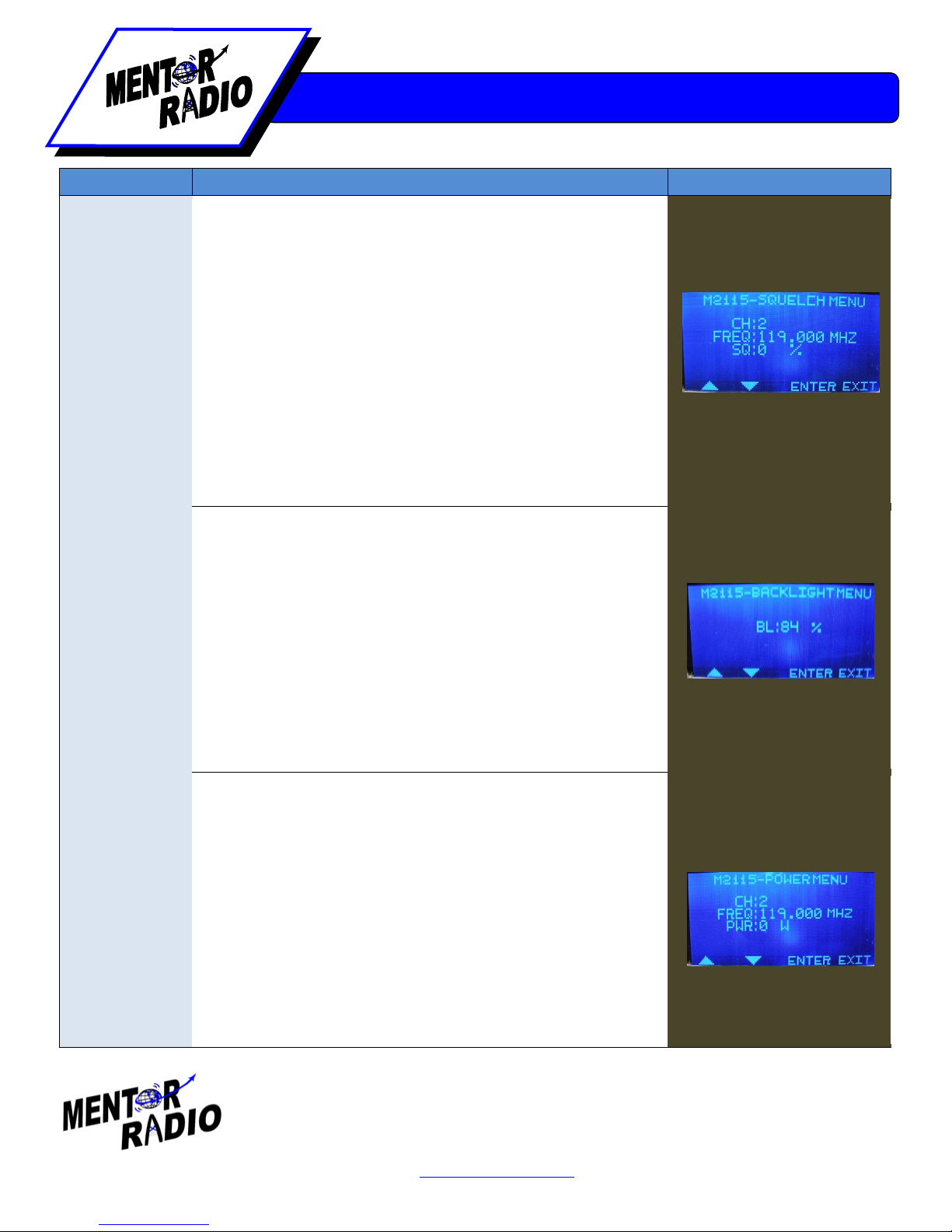
Squelch Adjust
Description:
The value that is displayed when the screen is first
loaded is the current channel’s squelch level. If the screen is
exited before button 3 is pressed, the last saved squelch value is
what the current channel has and not the value that is shown on
the screen (unless the two values are in fact identical).
Button 1: Increases the squelch value by 5% each press, up to a
maximum value of 100% for the channel that the radio is currently
tuned to.
Button 2: Decreases the squelch value by 5% to a minimum value
of 0% for the channel that the radio is currently tuned to.
Button 3: Saves the currently selected squelch value as the
current channels squelch value.
Button 4: Opens the Basic Settings screen.
Rotary Knob Rotate: Increases and decreases the squelch value
in 5% intervals.
Rotary Knob 1 Press: Performs the same function as button 3.
Rotary Knob 2 Presses: Performs the same function as button 4.
Backlight
Adjust
Description:
The backlight intensity changes as the value shown
on the screen changes, but unless button 3 is pressed before
exiting the backlight intensity will revert back to the last saved
value.
Button 1: Increases the backlight value in 4% intervals up to a
maximum of 100%.
Button 2: Decreases the backlight value in 4% intervals down to a
minimum of 0%.
Button 3: Saves the backlight value that is currently displayed.
Button 4: Opens the Basic Settings screen.
Rotary Knob Rotate: Increases and decreases the backlight value
in 4% increments.
Rotary Knob 1 Press: Performs the same function as button 3.
Rotary Knob 2 Presses: Performs the same function as button 4.
Power Adjust
Description:
Allows a user to alter the transmit output power for
the currently selected channel. Unless button 3 is pressed before
exiting, the transmit output power will revert back to the last saved
value.
Button 1: Increases the current transmit output power. The
interval and maximum value are dependent on the model of
M2115.
Button 2: Decreases the current transmit output power. The
interval and minimum value are dependent on the model of M2115.
Button 3: Save the value for the transmit output power as the
power value on the screen.
Button 4: Opens the Basic Settings screen.
Rotary Knob Rotate: Increases and decreases the power value.
Rotary Knob 1 Press: Performs the same function as button 3.
Rotary Knob 2 Presses: Performs the same function as button 4.
13
Phone: 216-265-2315 Fax: 216-267-2915
www.mentorradio.com (11/11)
M2115 OWNERS MANUAL
Solutions for Advancing Communications
Screen Name Actions Screen Shot
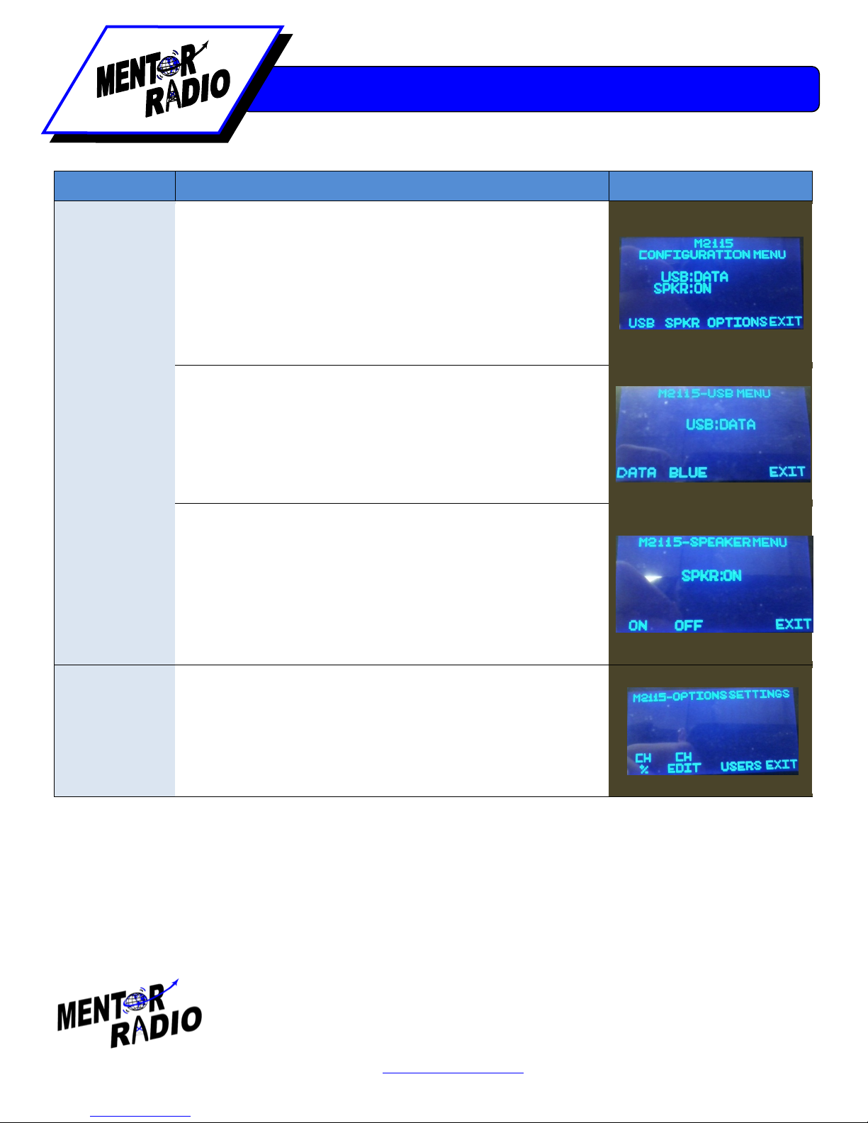
Configuration
Main
Button 1: Opens the USB screen.
Button 2: Opens the Speaker screen.
Button 3: If there are users entered into the system, then the Log
In screen is opened. Otherwise, the Channel and User
Configuration Main screen is opened.
Button 4: Opens the Main screen.
Rotary Knob Rotate: Nothing
Rotary Knob 1 Press: Nothing
Rotary Knob 2 Presses: Nothing
USB
Button 1: DO NOT USE. (Soon this screen will not exist.)
Button 2: DO NOT USE. (Soon this screen will not exist.)
Button 3: Nothing
Button 4: Opens Configuration Main screen.
Rotary Knob Rotate: Nothing
Rotary Knob 1 Press: Nothing
Rotary Knob 2 Presses: Nothing
Speaker
Button 1: The radio will send received audio signals to connected
radio speakers.
Button 2: The radio will not send received audio signals to
connected radio speakers.
Button 3: Nothing
Button 4: Opens Configuration Main screen.
Rotary Knob Rotate: Nothing
Rotary Knob 1 Press: Nothing
Rotary Knob 2 Presses: Nothing
Channel and
User
Configuration
Main
Button 1:
Opens Add or Delete Channel screen.
Button 2: Opens Channel Edit screen
Button 3: Opens Add Channel screen.
Button 4: Opens Configuration Main screen.
Rotary Knob Rotate: Nothing
Rotary Knob 1 Press: Nothing
Rotary Knob 2 Presses: Nothing

14
Phone: 216-265-2315 Fax: 216-267-2915
www.mentorradio.com (11/11)
M2115 OWNERS MANUAL
Solutions for Advancing Communications
Screen Name
Actions
Screen Shot
Add or Delete
Channel
Button 1: Opens Add Channel screen.
Button 2: Opens Delete Channel screen.
Button 3: Nothing
Button 4: Opens Channel and User Configuration Main screen.
Rotary Knob Rotate: Nothing
Rotary Knob 1 Press: Nothing
Rotary Knob 2 Presses: Nothing
Delete Channel
Button 1:
Goes through currently saved channels in an upward
direction.
Button 2: Goes through currently saved channels in a downward
direction.
Button 3: Deletes the currently selected channel.
Button 4: Opens the Add or Delete Channel screen.
Rotary Knob Rotate: Go up and down through the currently saved
channels.
Rotary Knob 1 Press: Performs the same function as button 3.
Rotary Knob 2 Presses: Performs the same function as button 4.
Edit Channel
Description:
There are two different focus groups for this screen.
The first group is the line marked “CH” and the second includes the
“FREQ” and “PWR” lines. Enter and Exit buttons control which
group the user is navigating. The current field that is in the group
that has focus will be blinking at a rate of one second.
Button 1: If in Group 1, does nothing. If in Group 2, selects
between the “FREQ” and “PWR” fields. No matter what the
position was in the “FREQ” field, the position will always start at the
100 MHz place holder.
Button 2: If in group 1, does nothing. If in group 2, the position in
“FREQ” is moved to the right one place holder. When at the 0.001
MHz place holder, the position wraps around to the 100 MHz place
holder.
Button 3: When in group 1, changes the focus to group 2 and
places the curser to the 100 MHz place holder position in the
“FREQ” field. When in group 2, the information displayed on the
screen is saved for the current channel displayed.
Button 4: When in group 1, opens Channel and User Configuration
Main screen. When in group 2, sets focus to group 1.
Rotary Knob Rotate: When in group 1, selects the channel whose
frequency and/or transmit power output is desired to be altered.
When in group 2, increases and decreases the value of the
currently selected field.
Rotary Knob 1 Press: Performs the same function as button 3.
Rotary Knob 2 Presses: Performs the same function as button 4.

15
Phone: 216-265-2315 Fax: 216-267-2915
www.mentorradio.com (11/11)
M2115 OWNERS MANUAL
Solutions for Advancing Communications
Screen Name
Actions
Screen
Shot
User Main
Button 1:
Opens the Edit User screen.
Button 2: Opens the Add User screen.
Button 3: Opens the Delete User screen.
Button 4: Opens the Channel and User Configuration Main screen.
Rotary Knob Rotate: Nothing
Rotary Knob 1 Press: Nothing
Rotary Knob 2 Presses: Nothing
Edit User
Description:
There are two different focus groups for this screen.
The first group is the line marked “USER ID” and the second
includes the “PASSWORD” and “ACCESS LVL” lines. Enter and
Exit controls which group the user is navigating. The current field
in the group that has focus will be blinking at a rate of one second.
If a user name is desired to be changed, the user must be re-
added.
Button 1: If in group 1, does nothing. If in group 2, selects
between the “PASSWORD” and “ACCESS LVL” fields. No matter
what the position of the cursor is in the “PASSWORD” field, the
position will always start at the far left place holder.
Button 2: If in group 1, does nothing. If in group 2, the position in
“PASSWORD” is moved to the right one place holder. When at the
10 place holders out, the position wraps around to the far left place
holder.
Button 3: When in group 1, the focus changes to group 2 and
places the curser to the far left place holder in the “PASSWORD”
field. When in group 2, the information displayed on the screen is
saved for the current user displayed on the screen and the focus
shifts back to group 1.
Button 4: When in group 1, opens User Main screen. When in
group 2, focus is set to group 1.
Rotary Knob Rotate: Increases and decreases the value in the
selected field at the cursor position.
Rotary Knob 1 Press: Performs the same function as button 3.
Rotary Knob 2 Presses: Performs the same function as button 4.

16
Phone: 216-265-2315 Fax: 216-267-2915
www.mentorradio.com (11/11)
M2115 OWNERS MANUAL
Solutions for Advancing Communications
Screen Name
Actions
Screen Shot
Delete User
Button 1:
Shuffles through users in an upward direction.
Button 2: Shuffles through users in a downward direction.
Button 3: Deletes the currently selected user.
Button 4: Opens the User Main screen.
Rotary Knob Rotate: Shuffles through users in an upward and
downward direction.
Rotary Knob 1 Press: Performs the same function as button 3.
Rotary Knob 2 Presses: Performs the same function as button 4.
Reset
Button 1:
Opens Reset Confirm screen, where the squelch value
for the currently selected channel will be reset to factory default.
Button 2: Opens Reset Confirm screen, where the backlight
intensity value will be reset to factory default.
Button 3: Opens Reset Confirm screen, where the radio is reset
to factory default settings and all channel and user information is
deleted. If users are in the system, the log in screen is opened
instead or Reset Confirm.
Button 4: Opens the Main screen.
Rotary Knob Rotate: Nothing
Rotary Knob 1 Press: Nothing
Rotary Knob 2 Presses: Nothing
Reset Confirm
Button 1:
Resets whichever option brought the user to this
screen.
Button 2: Opens the Reset screen.
Button 3: Nothing
Button 4: Opens the Reset screen.
Rotary Knob Rotate: Nothing
Rotary Knob 1 Press: Nothing
Rotary Knob 2 Presses: Nothing
Log In
Description:
A blinking cursor indicates what data the user is
currently manipulating.
Button 1: Changes the cursor focus to the field that is directly
above the current field. If the current field is “USER ID”, then the
field changes to “PASSWORD”.
Button 2: The cursor moves one place holder to the right in the
selected field. If the cursor is at the last place holder, then the
cursor moves to the far left place holder in the selected field.
Button 3: Opens the security protected screen that the user tried
getting to prior to the Log In screen being shown.
Button 4: Opens the screen that was displayed directly before
this one.
Rotary Knob Rotate: Increases and decreases the value in the
selected field at the cursor position.
Rotary Knob 1 Press: Performs the same function as button 3.
Rotary Knob 2 Presses: Performs the same function as button 4.

17
Phone: 216-265-2315 Fax: 216-267-2915
www.mentorradio.com (11/11)
M2115 OWNERS MANUAL
Solutions for Advancing Communications
Installation [7]
Notice [7.1]
The first consideration for installation is to choose a suitable location. For both mobile and base installations, installation of
the M2115 radio requires connecting the radio to a suitable antenna and a suitable power source.
NOTICE: For geographic locations where lightning is prevalent, Mentor Radio
recommends installing a lightning protector on the antenna coax. I used as a base
station radio, another lightning protector on the AC line is recommended.
M2115M [7.2]
The M2115M is intended to be installed into a vehicle. A suitable location should be selected to allow viewing of the GLCD
and access to the front panel controls. A mounting bracket is provided to allow mounting the M2115M under the dash or
on any flat surface. The bracket may be installed above or below the radio. Mobile antennas are available in two
versions; a thru-hole type and a magnetic mount type. Installing a thru-hole antenna requires drilling a hole in the vehicle
or mounting on a hood or roof of a vehicle. Magnetic mount antennas require routing the coax through the vehicle door
where water may leak in or where the coax may be pinched. This may shorten the life of the antenna. Therefore, it is
recommended to use a magnetic mount antenna for short term applications where the antenna may be removed and a
thru-hole type antenna for a permanently long term applications. Install the antenna and connect to the antenna
connector on the rear panel. Some antennas for aviation band frequencies come with a UHF connector. In this case, a
UHF to TNC adapter may be used to connect the antenna to the radio.
The M2115M includes a built-in speaker. However, an external speaker may be used with or instead of the internal
speaker. If an external speaker is to be used, install 18 AWG wires to the power plug as follows: Green wire to pin 12
(Speaker audio out signal) and a black wire to pin 2 (GND). A power cable is available which includes a 6 foot speaker
cable. External speakers and cables are sold separately.
Verify that the vehicle power is not greater than 14VDC. Connect the power cable to the vehicle power or battery (Red to
“+”, Black to “-”). Connect the 12-pin connector to the rear of the M2115M radio.

18
Phone: 216-265-2315 Fax: 216-267-2915
www.mentorradio.com (11/11)
M2115 OWNERS MANUAL
Solutions for Advancing Communications
M2115B-xx [7.3]
The M2115B can rest on a shelf or a desk when ordered as the standard tower mechanical configuration, or installed in a
rack mount when ordered in the rack mount mechanical configuration (M2115B-RM). Since this unit contains a cooling
fan, when located on a desk or shelf, do not place equipment, papers, magazines, etc. near where they would restrict air
flow through the left and right side vent ports thereby reducing its cooling capability.
Install a suitable power cord for local power used. A line replaceable fuse is inside the power plug. To remove the fuse,
the cord must be removed first which is done with lightly prying pressure. The exposed fuse is the operating fuse and a
spare fuse is located inside the fuse holder tray.
The antenna connector is a TNC style connector. If the antenna coax does not mate with this type, adapters are available
from Mentor Radio or from many electronic distributors.
The antenna should be either a wideband type (118-137 MHz) or a narrow band type tuned to single channel or a very
narrow range of frequencies. If a 3 or 6 dB gain antenna is used, communications range can be increased, because gain
antennas effectively increase both receiver sensitivity and transmitter power. Care should be taken using gain antennas
as many specify gain in a specific direction only. A directional antenna may reduce range in other directions in order to
increase gain in a single direction. Depending upon your application, this may be acceptable. Low loss coaxial cable is
also recommended, especially if the cable length exceeds 30 feet (10 meters).
Connections for remote operation for the M2115B-XX, when needed, are made via the 25 pin connector (type DB25) on
the rear of the cabinet. Theses cables must be custom made by Mentor Radio to fit the needs of the customer. The cable
is not standard, so please ask Mentor Radio to supply the cable with the radio. To install the interface cable, plug the
green housing into the back of the TTP (tone termination panel) and plug the DB25 connector into M2115B-xx. If there is
a custom interface that does not involve the TTP, then follow the instructions that Mentor Radio provides over the phone
or through e-mail for the custom configuration. Refer to Remote Control Installation [7.5] for installation/planning of a
remote control interface to work with the M2115B.
Plug a microphone into the microphone jack on the front panel of the M2115. Be sure the plug is pushed all the way into
the jack before turning the radio on.
Global Positioning System (GPS) Module [7.4]
Future feature, not currently available.
** To install the GPS module, a #2 Philips Head screwdriver is required.
1.) Remove the rear panel GPS module cover plate by unscrewing the two screws that hold the plate on.
2.) Press the GPS module connector onto the mating connector on the rear panel. Press firmly to ensure the
connector is fully seated.
3.) Install cover plate over module and fasten the two screws removed from step 1.
4.) Install GPS antenna in a suitable location. Route antenna cable to radio. Connect to the GPS module mating
connector (SMA style connector). NOTE: The GPS antenna must be exposed to the sky although placing it on a
dashboard may be acceptable. For optimal sky view an externally mounted antenna is better. Review user
requirements before deciding on antenna installation location.
5.) To enable the GPS feature of the radio, see the screen controls. ** This feature is not currently available.

19
Phone: 216-265-2315 Fax: 216-267-2915
www.mentorradio.com (11/11)
M2115 OWNERS MANUAL
Solutions for Advancing Communications
Remote Control [7.5]
Planning [7.5.1]
As a general guide for basic system design planning purposes, the following may help you in your
equipment requirement and selection process. Review Figure 1 for a summary of the pros and cons of
each system.
REMOTE
BENEFITS
DOWNSIDE
Local Extension Control: •Less expensive controllers •Distance limited (<1K ft)
•Hard to add controllers
•Requires special expensive cable
between each controller and radio.
•NO remote frequency selection
•Requires tools and technical skill to
connect wires to a terminal board.
Tone Remote Control: •Not distance limited •More expensive controllers
•Easy to add controllers •Requires a tone remote adapter
•Uses low cost phone wire to
connect between adapter and
radios.
•Allows remote frequency selection
•No tools required to install units.
Figure 1 - Comparison between Remote Control Systems
NOTE: As the engineering work for the Local Extension Controllers has not been completed, it is recommended
that the tone remote is selected if at all possible as the remote interface option. If a Local Extension Controller is
desired for cost reasons, the engineering work will be completed at that time but please be aware that the radio
will take longer to get out the door.
Installation [7.5.2]
The M2115B and M211B-XX have two different styles of connectors for remote interfaces: The M2115B provides the
connections necessary at the rear panel 12-pin power plug using a custom connector for connecting/disconnecting from
the remote interface, while the M2115B-XX series radios have a 25-pin connector on the back of the radio that the tone
remote interface connects to directly. This plugs for each radio contains all the connections needed for connecting
various types of remote controllers to allow remote users to operate the M2115B base station radio.
Each basic remote control type requires a different adapter cable to connect between the radio and the controllers. There
are four basic styles of controllers available for connecting to the M2115B, they are:
1. Telephone style handset
2. Desktop style with a pedestal style desktop microphone
3. Hands free voice operated transmit (vox) box
4. Dispatch style controller with a gooseneck microphone

20
Phone: 216-265-2315 Fax: 216-267-2915
www.mentorradio.com (11/11)
M2115 OWNERS MANUAL
Solutions for Advancing Communications
These 4 styles are available for both the local extension and tone remote controllers. Further, it is also possible to
interface the M2115B to a dispatch console. Most consoles allow interfacing many different types of radios, so make sure
the M2115B is configured as an analog radio.
This manual suits for next models
3
Table of contents


