AARIA
Cod. 20064783 Rev. 0
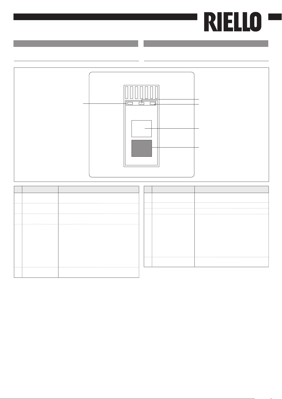
COMP TIMER OPER
1
2
3
IT
1. Avvertenze preliminari
Questa istruzione è parte integrante del libretto
dell’apparecchio sul quale viene installato il KIT. A tale
libretto si rimanda per le AVVERTENZE GENERALI e per le
REGOLE FONDAMENTALI DI SICUREZZA.
PANNELLINO RICEVENTE COMANDO
INFRAROSSI
2. Versioni
Codici
20064592 Pannellino ricevente comando infrarossi
In alcune parti del libretto sono utilizzati i simboli:
ATTENZIONE= per azioni che richiedono particolare
cautela ed adeguata preparazione.
VIETATO= per azioni che non devono essere
assolutamente eseguite.
3. Contenuto del kit
1 Pannellino ricevente comando infrarossi 1
2 Fascetta 1
3 Vite 1
Per una corretta installazione tener presente che il
pannello:
Deve essere installato su una parete, possibilmente
non perimetrale, che non sia attraversata da
tubazioni calde o fredde
In caso di installazione a parete deve essere fissato a
circa 1,5 m da terra.
Non deve essere installato in prossimità di porte
o finestre, apparecchi di cottura, termosifoni,
ventilconvettori o più in generale da situazioni che
possono generare perturbazioni alle temperature
rilevate.
Deve essere installato in considerazione della
lunghezza massima del cavo di collegamento.
4. Avvertenze preliminari
EN
1. Preliminary instructions
This instruction booklet is an integral part of the manual
of the device on which you install the kit. In that manual,
please refer to the WARNINGS and the BASIC SAFETY RULES.
INFRARED RECEIVER
2. Versions
Codes
20064592 Infrared receiver
The following symbols are used in this publication:
WARNING = actions requiring special care and
appropriate training.
DO NOT = actions that MUST ON NO ACCOUNT be
carried out.
3. Kit Contents
1 Infrared receiver 1
2 Belt 1
3 Screw 1
For correct installation, remember that the panel:
Must be installed on a wall, preferably not a perimeter
one, and one without any hot or cold pipes inside.
In the case of wall installation must be mounted at
1.5 m from the floor.
It must not be placed next to doors or windows,
cooking devices, radiators, fan coils or, more
generally, it must not be places in conditions that
might alter the measured temperatures.
The maximum length of the connecting cable must
be taken into account.
Use a shielded cable for the connection.
The connection cable must not be spliced; if splicing
is necessary, it shall be tinned and adequately
4. Preliminary instructions