Merax SW000009FAA User manual

Merax 14FT Trampoline with Enclosure
Assembly instruction, installation, use, maintaince and care
-
-
-
-
-
Don't try to somersaults or cartwheels. Falling on the head or neck can result in
paralysis or even death.
No more than one person at the same time making use of the trampoline. Multiple users
can increase the risk of injury.
Use the trampoline only under the supervision of an adult with knowledge of use. These
instructions are for your safety. Please carefully read each of them before assembly and
use of the trampoline. We retain this manual for future reference.
The maximum user weight should not exceed 330lbs / 150Kg for this product.
Read before using the product.
Telephone : 626-912-8886 Ext. 104
E-mail: csr@merax.com
Caution
USER MANUAL
1
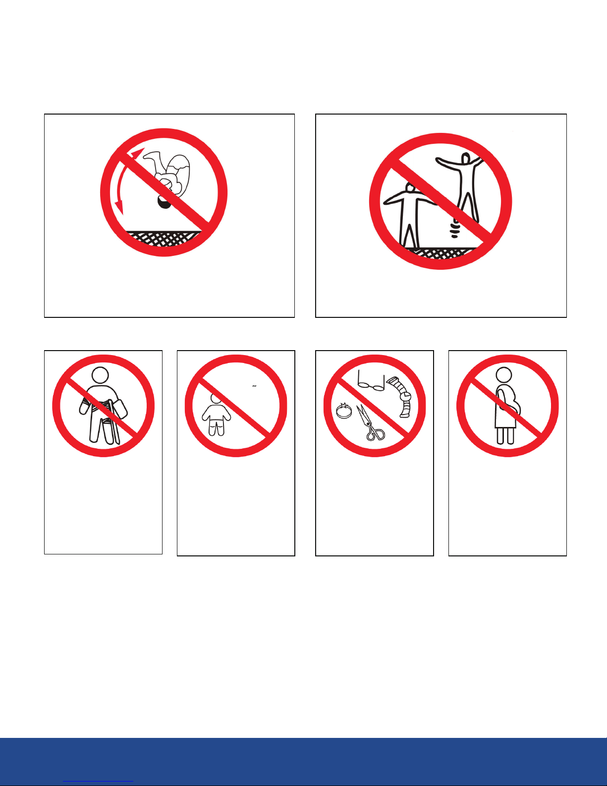
Caution
No flips or twists, a fall on the head or
Neck can result in paralysis or even
death.
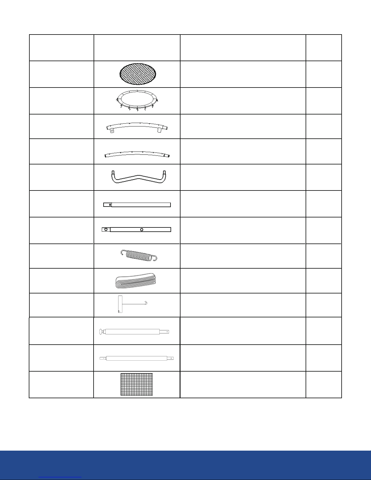
Do not use in
case of plaster
or any injury to
the leg, ARM,
Head, neck or
back.
Inspection before use, check that the legs are fixed, without Springs Loose, mesh, mat
and security are in place and in good condition without scratches.
Not more than one person at the same
time on the trampoline (330 lbs / 150 kg).
Do not allow the
use of the
trampoline for
children under
six (6) years of
age.
Remove all sharp
or Hard objects
such as Jewelry,
eyeglasses and /
or sunglasses
before jumping.
In case of
pregnancy, do
not use it without
your doctor's
consent.
0-6 ANOS
2
Number Diagram Description Quantity
1 Trampoline Mat 1
2 Frame Pad 1
3 Top Rails with Legs 6
4 Top Rail 6
5 Base Leg 6
6B
6A
Vertical extension leg
(Two Holes)
Vertical extension leg 6
6
7 Galvanized Springs
28N (5 1/2 "long)
8 Green PVC Sleeves 6
9 Loading Spring Tool 1
Part List - Trampoline
72
10 Top Frame Tube(with foam) 5
11 Bottom Frame Tube(with foam) 5
12 Mesh Cover 1
3
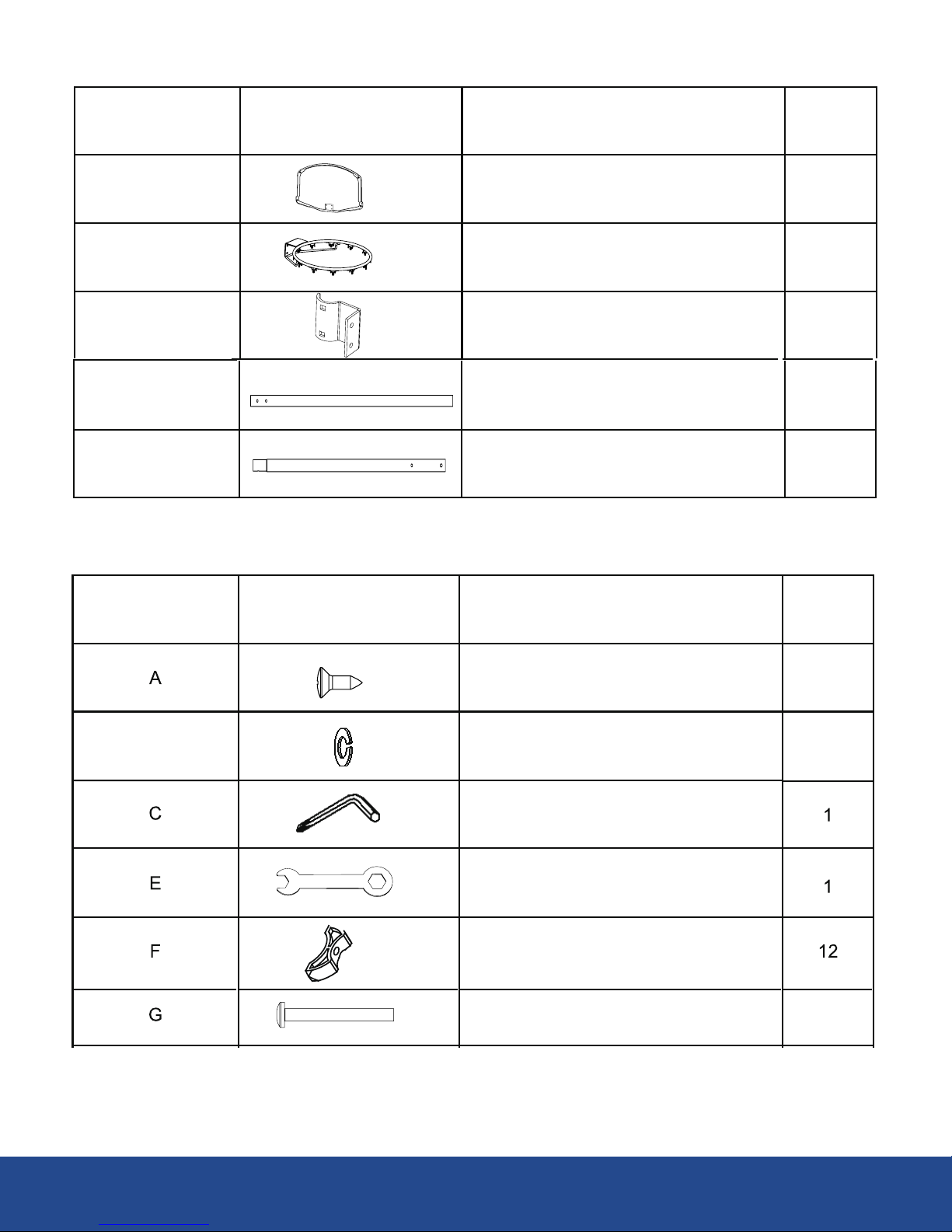
Part list - Tools
11
BSmall Spring Wahser
Screw
11
Allen Tool
Tool
Gap Spacer
Bolt 10
Basketball Hoop
Number Diagram Description Quantity
13 Board 1
14 Ring 1
15 Board connect hook 2
10A 1
11A 1
Upper Board Tube(No Foam)
Lower Board Tube(No Foam)
4
Number Diagram Description Quantity

Installation and Assembly instructions
This trampoline and the cover can be disassembled and stored easily by Reversing the order of the installation.
At least two people are required to assemble the trampoline and cover.
Before Assemble
Before Assembly, please make sure you have all the parts required to assemble the product. If a part is missing,
please contact our customer service agents.
8
Bolt 2
G1
Big Spring Wahser
Lock Nut 16
Arc Washer
1
Square Neck Bolt
Round Head bolt 4
Washer
M
N
O
Rope
V
X
Plastic Nut
Ladder
2
8
2
5

FIGURE 1
# 6B
# 4
# 5
# 6A
# 3
Assemble Frame of Trampoline
Before you start: check all the steps before assembling and Read All precautions before using the trampoline.
It requires at least two adults to assemble the trampoline. Must use Protective Gloves to avoid injury during the
Assembly
Locate the following 30 pieces of Steel Tubes that will need to begin to assemble the trampoline:
6 - Top rail with Legs (# 3)
6 - Top Rails (# 4)
6 - Base Leg (# 5)
6 - Vertical extension leg(# 6A)
6 - Vertical extension leg with two (2) Holes (# 6B)
Note: all parts are interchangeable with the same number and orientation have no right or left.
Make sure you have a spacious, clean and dry place, suitable for the assembly of the trampoline. It is essential that
the right place for this trampoline is completely flat and level. If the ground Is uneven, this could cause movement in
the frame and can cause stress in the united sections of the trampoline and / or can cause serious injury.
Step 1 - Assemble Frame
6
Step 2 - Leg Support Assembly
Connect the vertical extensions leg (# 6A and #6B) to the base leg (# 5) as shown in Figure 2 (The mounted parts
will be referred to hereafter as "Support Leg"). Repeat this step for all the support legs.
Note: The vertical extension leg (#6B) has two holes (2)
# 6B
# 6A
# 5
FIGURE 2
7

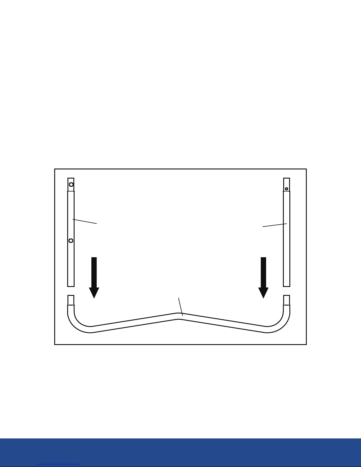
Step 3 - Main rail Assembly with screw
At this point, two people are needed to assemble the trampoline.
Lift two sets of legs brackets mounted in STEP 2 to a vertical position (standing). Connect one end of the top rail (# 3)
to the vertical extension of the leg (# 6A) and the other other end to the vertica leg extension with two holes (# 6B) as
shown in Figure 3 .
Repeat the same way for all the top Rails with Legs
Tip: Make sure that the holes in all parts of the steel pipe are aligned out (the holes in the legs both face
outwards in the same direction): This is important for the following installation of the net.
Support Leg
# 3
# 6A
# 6B
# 6A
# 6B
# 5
Holes
# 3
FIGURE 3
8

Step 4 - Top Rail Assembly
Complete the main frame by inserting top rail (# 4) on top rail (# 3) as shown in Figure 4.
Step 5 - Securing the support leg to the top rail.
Secure one side of the support leg - Extension of vertical leg (# 6A) to the frame using the locking screw (#A),
washer small security (# B) and Allen key (# C) as shown in FIGURE 5. If the holes do not match, turn the
extension of the Vertical leg back and forth to align the holes. Repeat the same way for all the leg holders.
NOTE:
The holes on the other side of the support leg will be used later, when installing the cover net - after all the springs
(# 7) have been installed (steps 7 - 10).
Do not overtighten the screws in this moment, screws should be tightened until the end
Tip: make sure that the holes in all the pieces of Steel Pipe Line and the hole is outwards. This is important for
the installation of the cover later.
# 6A # 6B
# 5
# 4
# 6A # 6B
# 3 # 3
# 6A
Turn the Vertical
extension leg to
align with the
drilling
Orifice
# B
# C
# A
FIGURE 4
FIGURE 5
9

Assembly of the trampoline Mat
To assemble the trampoline Mat, only need the Spring Loading Tool (# 9) included in this product.
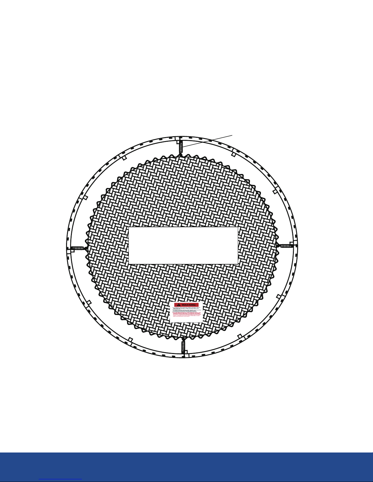
Step 6 - place the Mat
Place the trampoline Mat (#1) on the floor in the Interior of the frame assembled with the Label facing up as shown
in Figure 6. Align the warning labels with any of the trampoline legs, make sure that the warning labels are up. This
makes the installation process easier.
Select a starting point in the frame and name it "zero" point (pick a point that is above a frame leg and facing a
warning label).
Tool - Spring Loaded (# 9)
Trampoline Mat
(# 1)
Zero
FIGURE 6
10

STEP 7 - Assemble Springs
By placing the Springs, do not put hands, Arms, Legs or other body part near the connection Points (i.e., joints
Connecting Steel Pipe connection points) can become pinched points when the Springs are contracted. Use
Heavy Duty work gloves protect your hands from pinching by Springs and Protective Glasses to prevent Eye injury.
Make sure that no children playing nearby when joining in springs.
Starting at the "Zero Point", Connect one end of the Spring (# 7) with the spring load tool (# 9) in the triangular
ring and pull the other end securing it in the hole of the main frame, as shown in Figure 7.
Tap the end of the spring (# 7) with the handle of the spring load tool to ensure that the springs are securely
locked into the hole.
FIGURE 7
Springs (# 7)
Triangular Rings
Trampoline Mat
Frame Spring Load Tool (# 9)
ZERO
11
Step 8 - Assemble Springs
After having secured the spring in the "Zero Point", Count to 36 holes on the opposite side of the frame and put a
Spring in the same way as in the previous step. For a uniform distribution of the spring tension and ease of installation,
the springs must always be installed at opposite sides of the main frame of an Alternating Way, i.e., Zero after 36,
followed by 18 and 54 as shown in Figure 8.
Tip: the number of triangular Rings sewn in the table is equal to the number of holes in the main frame. Note that
if you miscounted a triangular hole or ring, remove and reinstall the Springs in the necessary Place, maintaining a
uniform distribution of tension as detailed above.
36
ZERO
18
54
SPRINGS (#7)
Trampoline Mat
(# 1)
FIGURE 8
12
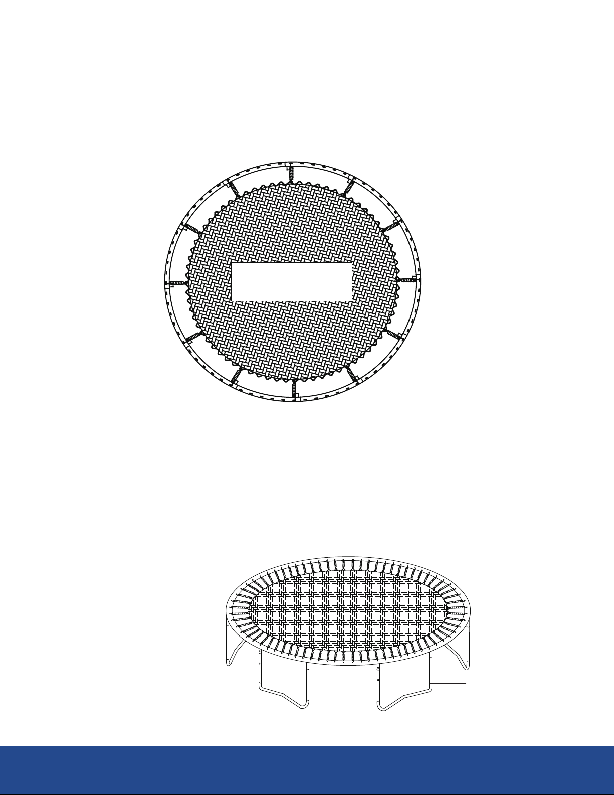
Step 9 - Assemble Springs
Place a spring each interval of the sixth hole. For a uniform distribution of tension and ease of assembly, the springs
should be placed on opposite sides of the main frame Alternatively, IE 6 after 24 and 42, 60, etc. besides the Springs
above should now have Springs at 6, 12, 24, 30, 42, 48, 60 and 66, as shown in Figure 9.
Step 10
Continue placing the remaining 60 springs in the same manner as in the previous step. The springs shall be placed
on opposite sides of each one to make sure that the trampoline Mat is taut perfectly.
IMPORTANT: you must make sure the springs are perfectly placed and return to step 5 and tighten the screws
of the support legs
60
18
36
54
24
48
66
ZERO
12
30
42
6
Trampoline Mat
(# 1)
Support Leg
FIGURE 9
FIGURE 10
13
Assemble Frame Pad
Never use the trampoline without the frame pad, the pad frame reduces the risk of injury by striking the metal
structure. Inspect the cushion frame and metal parts are completely covered by the frame pad before each use.
Note: Please ensure that the warning label is placed between the support leg main frame,
as shown below: This is to ensure that the label is in front of the entrance trampoline
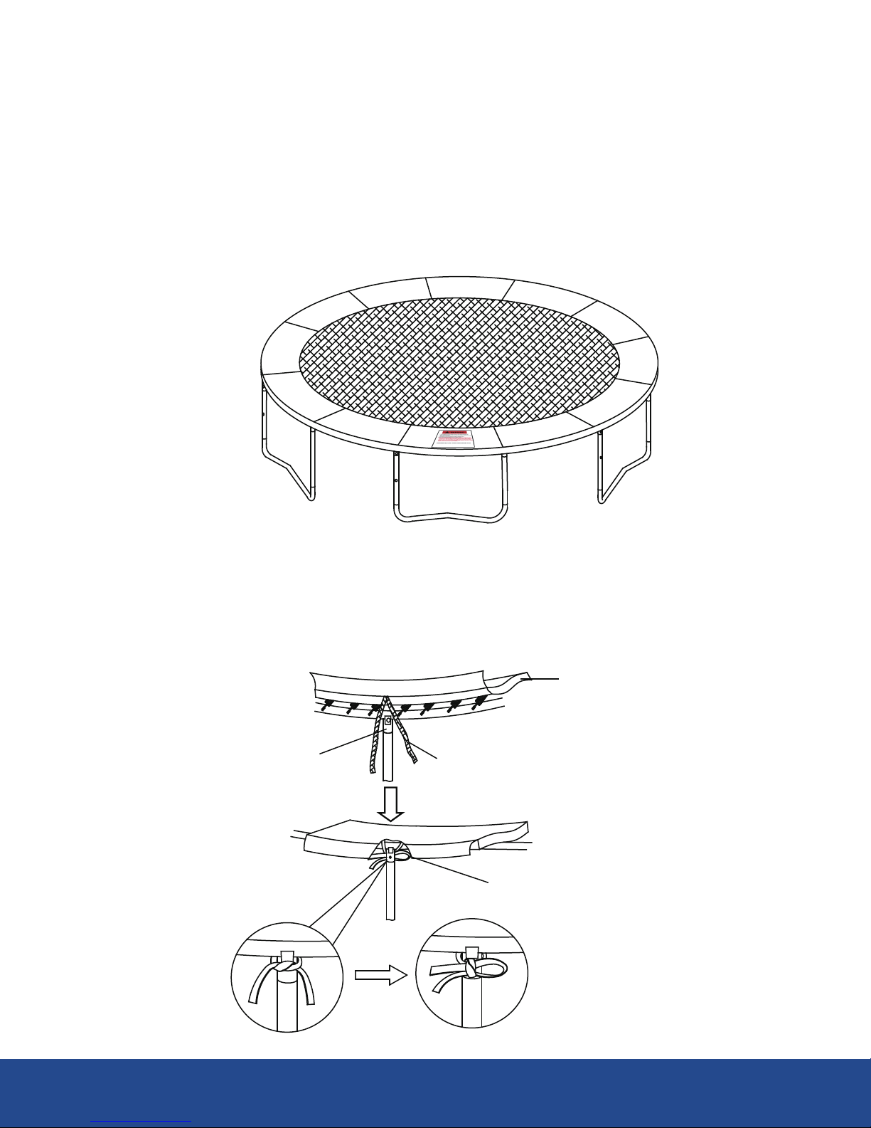
Step 11
Place the Frame Pad (#2) on the trampoline and fully cover the springs and steel frame. Align the straps to leg sockets
and wrap the elastic straps to the connectors of the legs. First, tie a knot and then tie in a bow on one side, as shown
in Figure 11. Repeat this step for all the outer bands.
Connectors of the legs Elastic straps
Frame Pad (# 2)
Behind the connectors of the legs
Elastic straps
FIGURE 11
14

Step 12
Finally, wrap the internal elastic straps around triangular ring and tie a knot as shown in the diagram, then tie in a
bow on one side as shown in Figure 12. Repeat this step for all inner bands.
Make sure the knots and ties are tight for all elastic straps
Make sure the pad frame is securely installed in the frame and completely covers the frame and all springs before
using the trampoline. Do not use the trampoline if a triangular ring fails or is damaged.
Conduct a full Inspection of the trampoline to ensure that all parties are properly assembled.
Read This Manual and make sure you fully understand all warnings in the various Warning signals.
Disassembly of Trampoline
-
If you have to disassemble the trampoline please follow the assembly instructions in the opposite direction and take
special care to keep the parts. Keep the original packaging for transport.
Elastic straps
FIGURE 12
Expanded Diagram
Frame Pad (#2)
Triangular Rings
15
Assembly of the Trampoline Mesh Cover
Before you start:
This trampoline should only be used when the network is assembled correctly. The net of the trampoline must be
revised thoroughly before each use to ensure that there are no breakages or damage. PLEASE READ
CAREFULLY ALL the important safety instructions in this manual and all warnings on the product before use
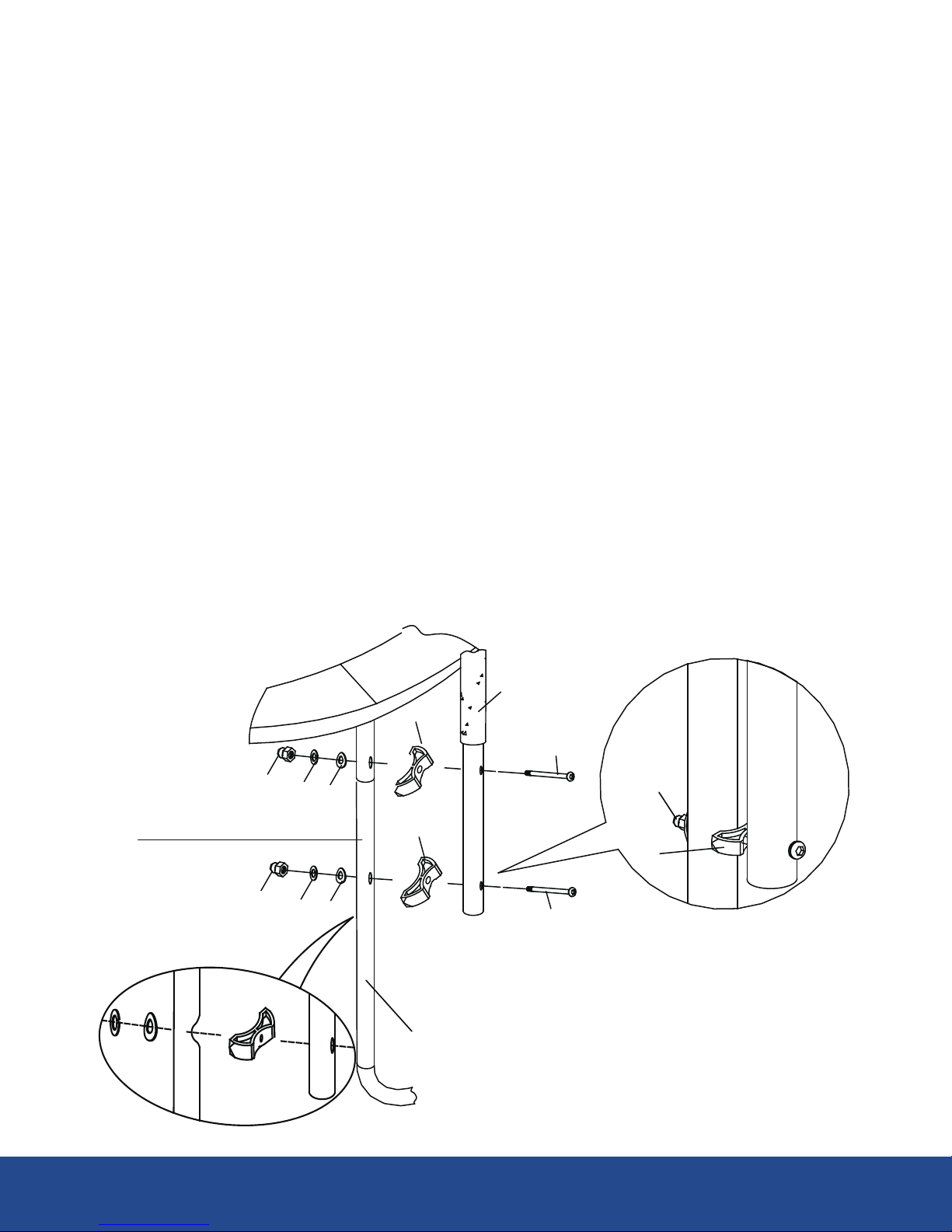
Step 13
FIGURE 13
Place bottom frame tube (with foam) (# 11) next to the support leg(i.e., the side with the 2 Holes) and
secure it with the screw bolt (#G) , gap spacer (#F), arc wahser (#J) , big spring wahser (#H) and Lock
Nut(#I) as shown in Figure 13.
Repeat this step for the rest 4 bottom frame tubes(with foam)
Place lower board tube ( # 11A) next to the last support leg and secure it with the screw bolt (#G1) , gap
spacer (#F), arc wahser (#J) , big spring wahser (#H) and Lock Nut(#I)
6B
Expanded Diagram
Frame of the leg
# F
# I
# F
# I # H # J
# F
# I # H # J
# 11
# G
#G
16
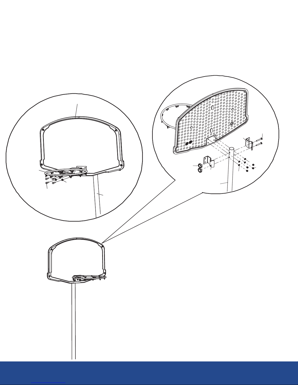
FIGURE 14
#M
#15
#V
#15
#I
# O
#13
#10A
#N
#14
#O #10A
Connect Board (# 13) and Ring(#14) with the Round Head Bolt (#N) , Wahser (#O), as shown in Figure 14.
Connect the backboard to Upper Board Tube (#10A) using Board Connect Hook (#15) and secure it with Square
Neck Bolt (#M) , Plastic Nut(#V), secure Round Head bolt (#N) with Wahser(#0) and Luck Nut (#I). Cover the
Upper Tube(#10A) with Green PVC Sleeves (#8) from bottom.
17
Step 14

Connect Upper Board Tube (#10A) and Lower Board Tube (#11A) with "U" pin, Make sure the Basketball
Board faces inward the trampoline.
Connect Top Frame Tube (#10) and Bottom Frame Tube (#11) with screw (#A), Small Spring Wahser (#B) and
Allen tool (#C),
After all the tubes are connected, slip the Green PVC Sleeves (#8) onto the top frame tube(#10).
Step 15
# 10A
# 11A
#10
#11
FIGURE 15
# B
# C
# A
Connect Top Frame Tube (#10) and Bottom Frame Tube (#11) with screw (#A), Small Spring Wahser (#B) and
Allen tool (#C)
#8
18
U pin
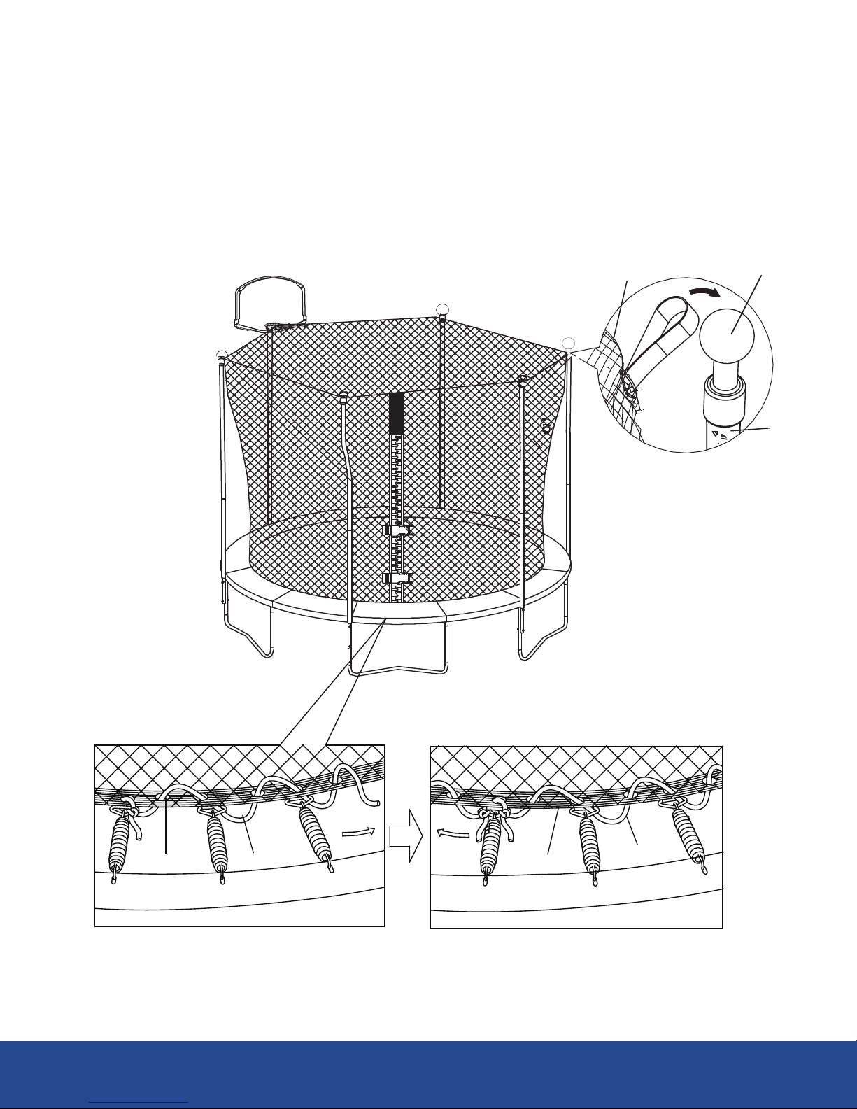
FIGURE 16
# L
# 12 # 12 # L
Install the strap circle to the top of the frame (# K1) as shown and then tie the other end of the strap to the
top(# K1). Please make sure the door is closing at the zero point
19
# 12 # K1
# 10
Step 16
Tie the end of the cable (# L) to the first ring of the trampoline, pull cord (# L) through all the rings on
the trampoline frame, then tie the two ends of the rope together.
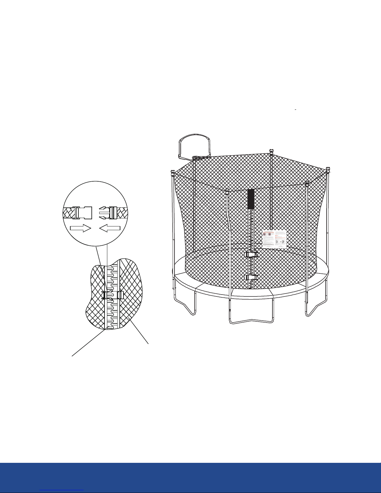
Pull the trampoline enclosure (# 12) to the door, then press two buckles as (the bottom of
the buckle not shown) shown in FIGURE 17.
FIGURE 17
Make sure the trampoline is on a flat, level surface with adequate safety distances in case you need to move from
place to place. If you have to remove the trampoline please follow the assembly instructions in reverse and take
special care to keep the parts. Keep the original packaging for transport.
Zipper
#12
Step 17
20
Table of contents


