Frick RTF 201 User manual

RTF
Rooftop Freezer Systems
Form 200.108-IOM (FEB 2018)
INSTALLATION - OPERATION - MAINTENANCE
File: SERVICE MANUAL - Section 200
Replaces: 200.108-IOM (MAY 2015)
Dist: 1, 1a, 1b, 1c, 4, 4b, 4c
THIS MANUAL CONTAINS RIGGING, ASSEMBLY, START-UP,
AND MAINTENANCE INSTRUCTIONS. READ THOROUGHLY
BEFORE BEGINNING INSTALLATION. FAILURE TO FOLLOW THESE
INSTRUCTIONS MAY RESULT IN PERSONAL INJURY OR DEATH,
DAMAGE TO THE UNIT, OR IMPROPER OPERATION.
Please check www.johnsoncontrols.com/frick for the latest version of this publicatio
n.

200.108-IOM (FEB 2018)
Page 2
RTF ROOFTOP FREEZER SYSTEMS
INSTALLATION - OPERATION - MAINTENANCE
Indicates an imminently hazardous situation which, if not avoided, will result in death or serious
injury.
Indicates a potentially hazardous situation or practice which, if not avoided, will result in death or
serious injury.
SAFETY PRECAUTION DEFINITIONS
Indicates a potentially hazardous situation or practice which, if not avoided, will result in damage
to equipment and/or minor injury.
Indicates an operating procedure, practice, etc., or portion thereof which is essential to highlight.
DANGER
WARNING
CAUTION
NOTICE
IMPORTANT! READ BEFORE PROCEEDING!
This manual provides the information needed for safe installation, operation, and maintenance for Roof Top Units. Close attention
to the instructions provided in this manual will ensure proper installation and operation, and a long satisfactory unit life.
It is strongly recommended that one becomes fully familiar with this manual prior to operating or working on a Roof Top Unit.
After installation the unit must be properly connected to an appropriately designed and installed refrigeration system. The engi-
neering plans, piping layouts, etc., must be detailed in accordance with local codes and applicable industry standards and practices.
Units should be rigged and installed as outlined in this manual. These procedures should be reviewed in detail prior to the actual
rigging operation to acquaint all personnel with the procedures to be followed.
If any questions or comments arise regarding this manual, we encourage you to call your sales representative.
CHANGEABILITY OF THIS DOCUMENT
In complying with Johnson Controls policy for continuous product improvement, the information contained in this document is
subject to change without notice. While Johnson Controls-Frick makes no commitment to update or provide current information
automatically to the manual owner, that information, if applicable, can be obtained by contacting the nearest Frick Factor or the
nearest Frick Sales of!ce.
It is the responsibility of operating/service personnel to verify the applicability of these documents to the equipment in question. If
there is any question in the mind of operating / service personnel as to the applicability of these documents, then prior to working
on the equipment, they should verify with the owner whether the equipment has been modi!ed and if current literature is available.
WARNING
External wiring is NOT to be connected inside an RTF factory mounted electrical panel unless specifically indicated as
required field wiring on the JCI - Frick electrical drawings provided. Devices such as relays, switches, transducers and
controls may NOT be installed inside the Frick RTF electrical panel. NO external wiring is allowed to be run through
the Frick RTF electrical panel. All wiring must be in accordance with Johnson Controls-Frick published specifica-
tions and must be performed ONLY by qualified Johnson Controls-Frick personnel. Johnson Controls-Frick will not
be responsible for damages/problems resulting from improper connections to the controls or application of improper
control signals. Failure to follow this will void the manufacturer’s warranty and may cause serious damage to property
or injury to persons.

200.108-IOM (FEB 2018)
Page 3
RTF ROOFTOP FREEZER SYSTEMS
INSTALLATION - OPERATION - MAINTENANCE
Contents
GENERAL INFORMATION
RECEIVING AND INSTALLATION........................................................................................................................................ 4
SAFETY .......................................................................................................................................................................... 4
WARRANTY ..................................................................................................................................................................... 4
PREINSTALLATION REQUIREMENTS
TRAINING & SAFETY CONSIDERATIONS ...........................................................................................................................5
PRELIMINARY SITE LAYOUT CONSIDERATIONS .................................................................................................................5
PRELIMINARY FIELD PIPING
DESIGN CONSIDERATIONS .......................................................................................................................................5
ELECTRICAL POWER ........................................................................................................................................................ 6
REFRIGERATION ............................................................................................................................................................... 6
CONDENSATE DRAIN ....................................................................................................................................................... 6
INSTALLATION
INSTALLATION SAFETY GUIDELINES..................................................................................................................................7
SUPPORT STRUCTURE INFORMATION ..............................................................................................................................7
RTF SUPPORTED BY ROOF CURB ......................................................................................................................................8
JCI-FRICK SUGGESTED ROOF TO CURB FINISH ..............................................................................................................8
RTF SUPPORT LAYOUT DIMENSIONS ................................................................................................................................8
ROOF CURB ..................................................................................................................................................................... 9
RTF UNIT ........................................................................................................................................................................ 9
DISCHARGE AIR PLENUM ................................................................................................................................................12
ELECTRICAL ....................................................................................................................................................................13
REFRIGERATION ..............................................................................................................................................................15
OPERATION
START-UP.......................................................................................................................................................................16
MAINTENANCE
UNIT EXTERIOR ............................................................................................................................................................. 17
COIL MAINTENANCE ....................................................................................................................................................... 17
NOTICE
This manual, in combination with the applicable cooling coil data, unit G&A drawing, unit electrical drawing, roof curb
drawing, and, discharge plenum drawing, provides the information necessary to safely install and start up a Frick RTF
unit. Due to the possibility of customization associated with the RTF product line, there may be areas beyond the scope
of this manual. If there are any questions about a special application lacking the required information, please contact
the installing contractor or your local Frick Sales Office.

200.108-IOM (FEB 2018)
Page 4
RTF ROOFTOP FREEZER SYSTEMS
INSTALLATION - OPERATION - MAINTENANCE
GENERAL INFORMATION
RECEIVING AND INSTALLATION
SHIPMENT INSPECTION
Once the unit has arrived at the job site, do not accept
delivery of the unit until it has been inspected. This is to
ensure that all required parts have been received and are
free of shipping damage. Unpack all items and compare with
the shipping lists.
Contact your sales representative to report any missing items.
Signature acceptance of equipment implies that the RTF unit
and all loose components are complete and free from defects.
The following parts should be inspected:
Roof Curb
Discharge Plenum
Enclosure Plugs for the lifting lug locations
Transition Ducts
Roof Flashing
Miscellaneous Hardware
In addition, check the coil to see that the internal gas holding
charge remains intact (15 psi - 25 psi). This charge must be
maintained until refrigerant piping is connected to the unit.
A coil that does not have a charge may have been damaged
during transit. If the charge is not present when the unit is
received, the coil must be pressure tested with dry nitrogen
gas to con•rm that it is free of leaks.
Leak Check Procedures:
• Install a pressure gauge with a range of 200 psi - 400 psi
• Apply a 100 psi to 150 psi charge of dry nitrogen
• Hold the charge for 24 hrs and observe any signi•cant
changes in pressure
• (The nitrogen charge may change 1-2 psi per 10 degree
change in temperature)
Check motor supports, fan, and fan guard fasteners for tight-
ness. Some fasteners may have loosened during transportation.
TRANSIT DAMAGE AND SHORTAGE CLAIM
The consignee must make all damaged freight claims. This
is an ICC requirement. Request immediate inspection by the
agent of the carrier and be sure all proper documentation is
executed. A copy of the damage claim should also be sent
to the JCI-Frick Service and Warranty department.
Shortage claims should be sent directly to the JCI-Frick sales
representative and the JCI-Frick factory sales department
For either claim, please include the RTF unit model number,
the serial number and the JCI-Frick Sales Order number.
All of this information is shown on the RTF unit nameplate.
SAFETY
The customer is responsible for providing quali•ed and
trained personnel to install and operate the equipment.
Consult all local building, occupational safety, electrical, gas,
and other codes applicable to the installation.
A variety of optional safety features are available from the
manufacturer. It is the responsibility of the owner to deter-
mine if the unit is equipped with all of the safety devices
required for the particular application.
Safety considerations include:
1. The accessibility of the equipment to nonservice personnel.
2. The provision of electrical lockout switches.
3. Maintenance procedures.
4. Automatic control sequences.
CAUTION
Users and installers of this equipment should be aware
of all recommended safety procedures and information
such as AMCA publication 410-90 Safety Practices.
CAUTION
Never open an access door while air unit is in operation.
CAUTION
A fan, even though locked out electrically, can rotate
in a seemingly insignificant air flow. During maintenance
the fan blades should be secured to restrict rotation.
Verify that the restrictive device is removed before
putting the fan back into service.
CAUTION
Equipment wired to automatic control devices may start
without warning, resulting in personal injury or prop-
erty damage. In many instances, a unit will have mul-
tiple electrical connection points. To prevent unforeseen
start-up prior to beginning work on an RTF unit, always
lock out all power supplies.
CAUTION
Always replace any protective covers removed for ser-
vicing.
CAUTION
Always replace bolts or locks on latches of access doors
that provide access to areas with moving parts. This
mechanical protection from moving parts is required by
UL 1995.
CAUTION
A number of additional safety issues are discussed
throughout the manual. Please read the complete
manual prior to installing, operating, or servicing the
equipment.
WARRANTY
NOTICE
For warranty support with the Frick RTF unit, contact
Frick Service at 717-762-2121.

200.108-IOM (FEB 2018)
Page 5
RTF ROOFTOP FREEZER SYSTEMS
INSTALLATION
PREINSTALLATION REQUIREMENTS
TRAINING & SAFETY CONSIDERATIONS
The Johnson Controls – Frick RTF evaporator design utilizes
the •nest materials and corrosion protection to deliver de-
pendable and consistent cooling for coolers and freezers.
This manual provides the information needed for safe instal-
lation, operation, and maintenance. Close attention to the
instructions and guidelines provided will ensure the longest
possible system life and dependable, consistent performance.
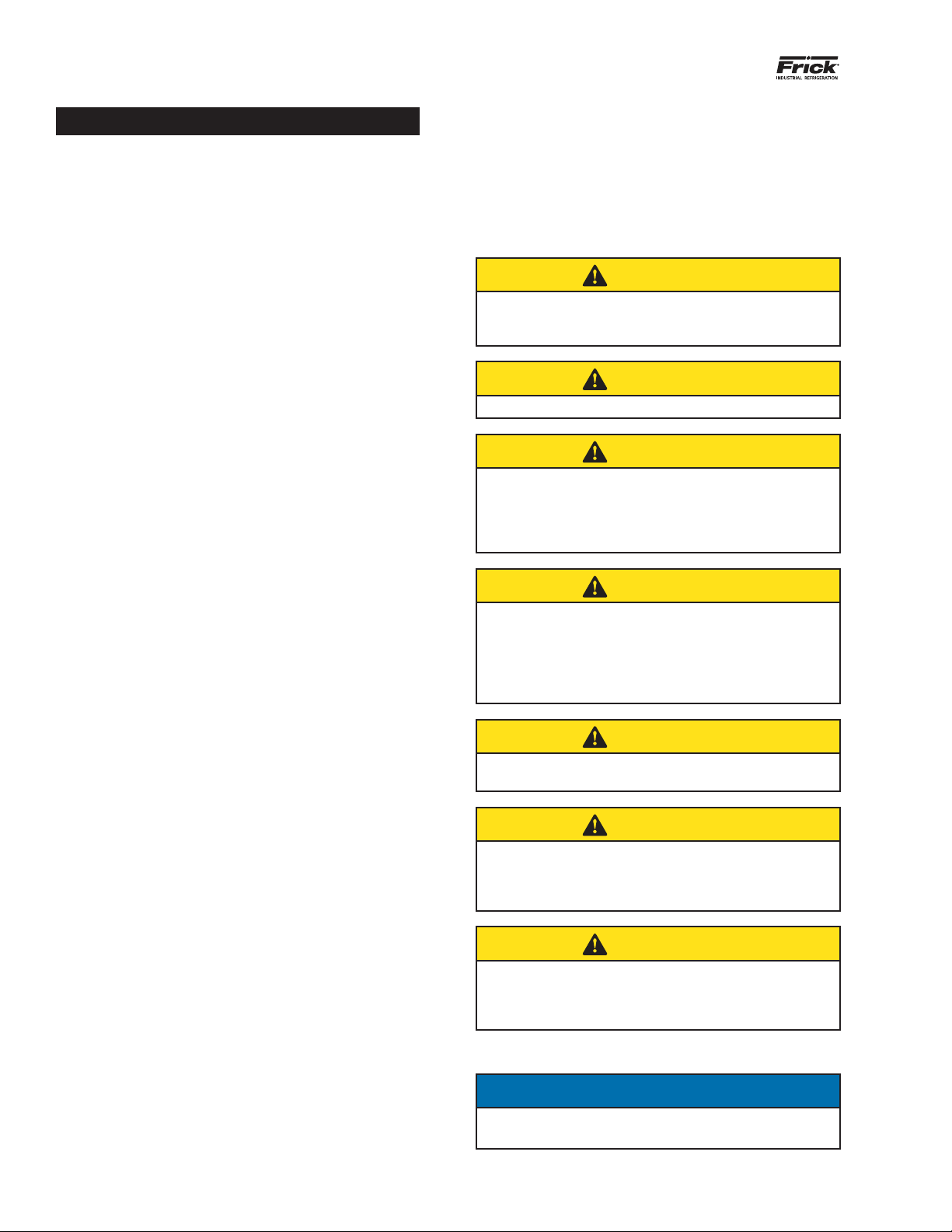
CAUTION
JCI-Frick recommends that only experienced industrial
refrigeration contractors, operators, and maintenance
technicians be used to install, operate and maintain the
RTF unit. Before working on the RTF unit, it is further
recommended that they be provided formal training on
the RTF’s design and features that incorporates reading
and understanding this manual.
Installation, operation, and maintenance of the Frick RTF unit
involves rotating machinery operating at high speed and high
voltage. Normal operations and maintenance procedures may
require working at elevations, entry into enclosed spaces,
and the use of hand and power tools. Taking these consid-
erations into account, it is clear that safety should always
be the top priority.
We recommend that every site installing an RTF unit analyze
and develop an installation-speci•c safety regime that takes
into account such variables as speci•c site and unit features,
personnel quali•cations, hazard identi•cation, etc.
NOTICE
Configure all power switches and controls to provide an
open, safe circuit before and during maintenance pro-
cedures, until the system is cleared by management for
normal on-line operations. For extended shutdowns, it
is recommended that a qualified technician remove fuses
from “fused-disconnect panels” or otherwise open the
circuit in an accepted, secure manner.
JCI-Frick recommends that the following elements related
to operational safety be incorporated into every client's RTF
safety requirements and safety program.
Fans – All fan covers, guards, and shaft retainers (if any)
must be in place before applying power to an RTF unit. Al-
ways disengage and lock out power before allowing interior
inspections. To prevent foreign objects from being sucked
into rotating fan blades, never allow operation with the
doors open.
Enclosed space inspections – Inspections of coils, drain
pans, guards, etc., require machinery lockout and the use
of a “lookout buddy” at a minimum – consult your internal
safety policy and OSHA requirements for additional recom-
mended safety procedures.
Vibration and noise – Discontinue or stop machinery that
emits unusual vibration and noise. The source of the distur-
bance must be investigated, identi•ed, and corrected before
testing or placing the system back in operation.
Wet Surface Precautions – Poorly maintained and wetted
machinery requires care to avoid electrical shocks from in-
adequate or loose •eld wiring and connections. All personnel
must lock out and tag machinery before working on the unit.
Proper safety precautions such as the use of insulating soles
and gloves and a trained “lookout buddy” are indispensable.
Ice formation in cold weather can present slip and fall haz-
ards around a rooftop penthouse unit. Ice related safety
procedures should be mandatory when the daily ambient
temperature falls below 40°F.
RTF units typically operate in a continuous-duty capacity and
must be properly located, installed, and connected in the
•eld (by others). It is imperative that the electrical power and
control wiring, refrigerant lines and air duct be adequately
sized and properly installed. The engineering plans, piping
layouts, etc. for all peripheral “•eld” work should be detailed
in accordance with local and governing codes and the best
industry standards and practices.
If you have any comments or questions regarding this manual
or the RTF unit, you are urged to call your installing contrac-
tor and/or the local Frick sales representative.
PRELIMINARY SITE LAYOUT CONSIDERATIONS
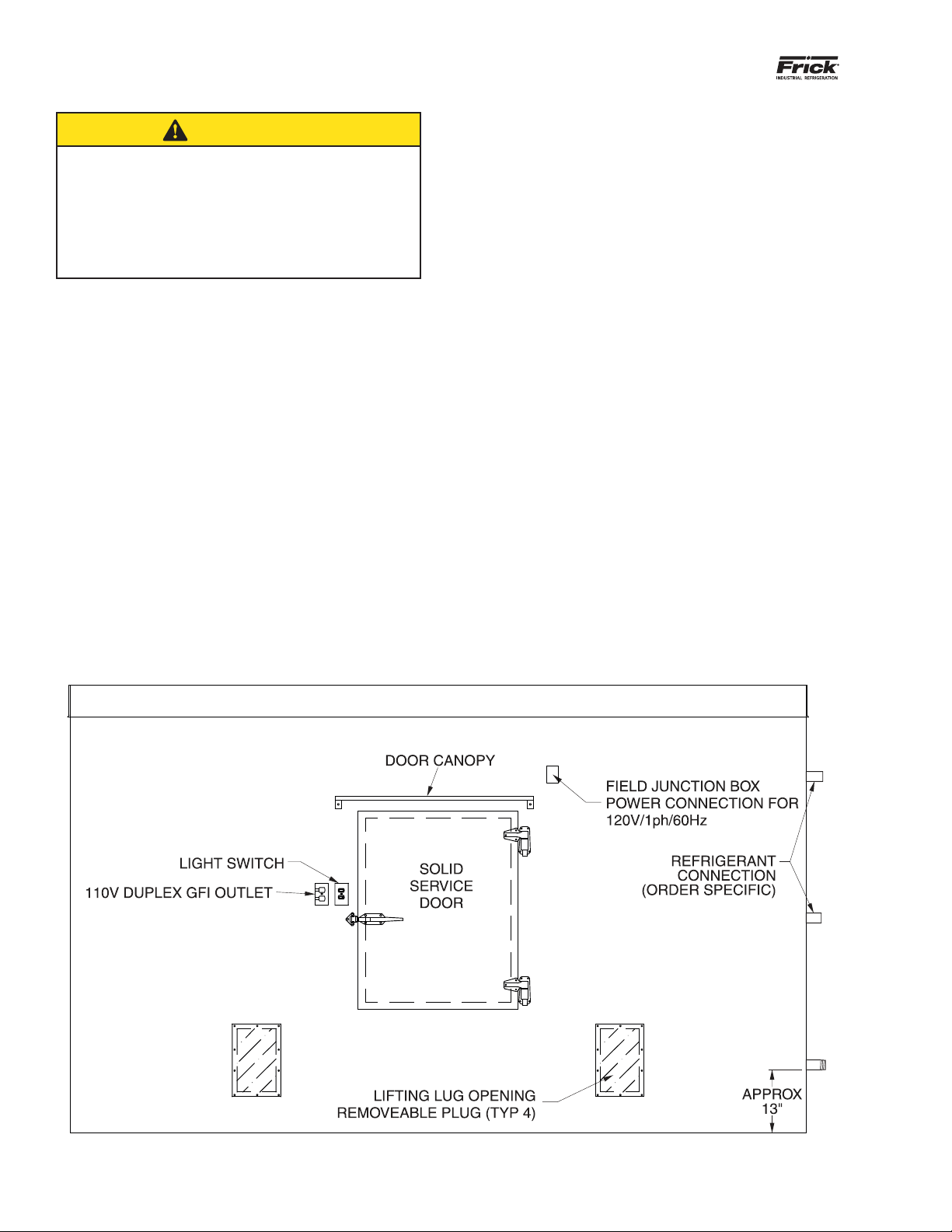
All Frick RTF units must be located for accessibility on the
roof and air !ow in and out of the cold space. The Frick RTF
enclosure has two access doors, one on either side of the
unit. Provision must be made for service and maintenance
access to both of these locations.
Air is drawn into the RTF unit along one side, entering up-
ward through the bottom of the unit. Colder air is discharged
downward along the opposite side of the unit. Adequate
free !ow area must be available for returning air to enter
the bottom of the RTF unit. Excessive restriction will reduce
the air !ow and thus the cooling capacity of the RTF unit
It is the owner’s responsibility to properly locate the RTF
unit in consultation with a quali•ed engineer before laying
out structural supports and installing the penthouse unit.
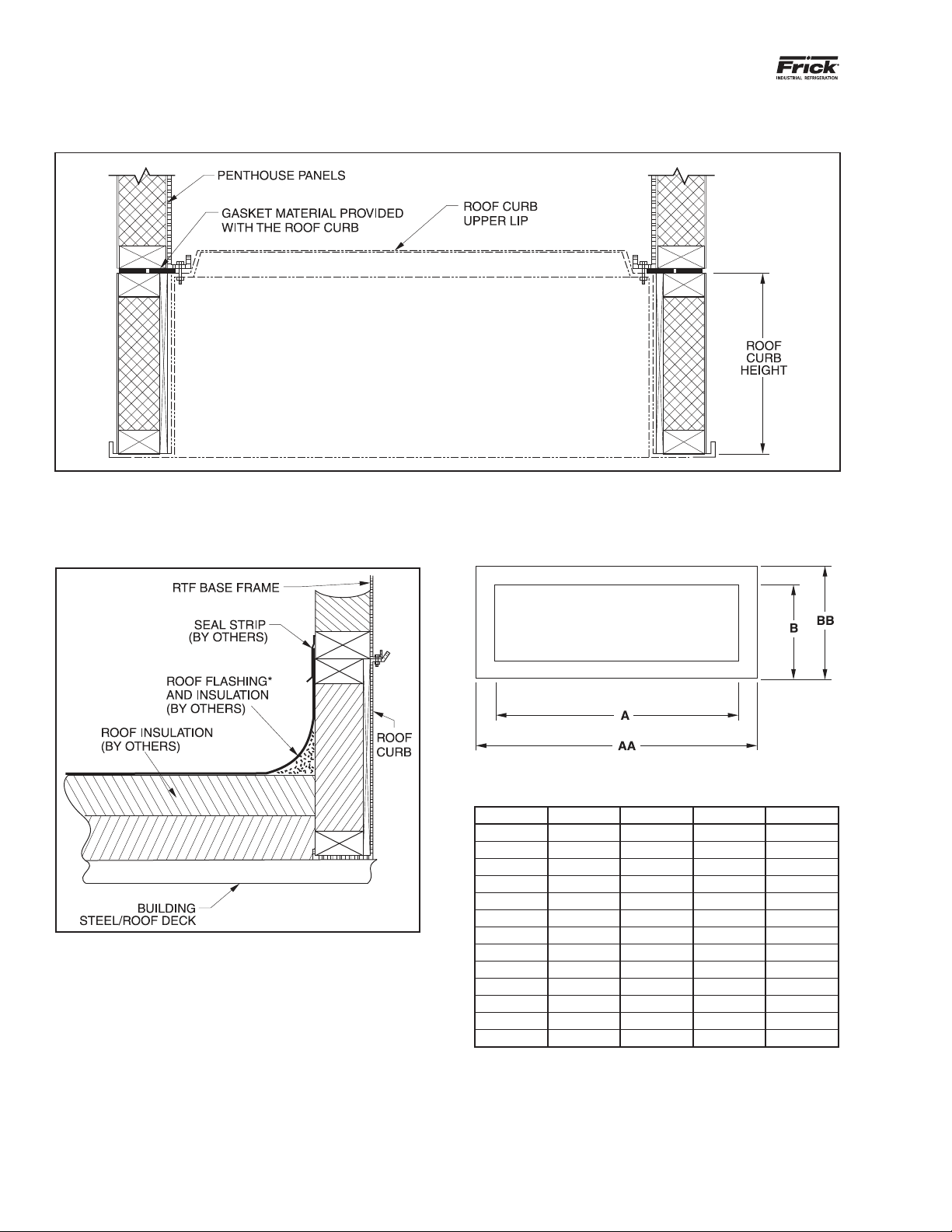
In general, Frick RTF units must be uniformly supported
around the perimeter either by roof curb or building structural
steel under roof decking.
PRELIMINARY FIELD PIPING
DESIGN CONSIDERATIONS
Before •nalizing the refrigerant piping plans for the new
RTF unit, it is recommended that related plans for potential
expansion of the refrigeration system and building be dis-
cussed with your refrigeration system designer and Johnson
Controls-Frick®sales representative. Incorporating appropri-
ate pipe and opening sizes now (in light of existing and future
needs) is often the most economical long term strategy.
CAUTION
Avoid hydraulic lockup caused by trapped liquid. When
there is an increase in ambient temperature and liquid
refrigerant confined in rooftop piping, the resulting
expansion pressure has the potential to cause
refrigerant lines to burst.

200.108-IOM (FEB 2018)
Page 6
RTF ROOFTOP FREEZER SYSTEMS
INSTALLATION
CAUTION
All Frick RTF units require strongly supported and prop-
erly anchored field piping. NO field piping is to be sup-
ported by the RTF unit enclosure itself. Wind loading,
temperature variation, etc., must be considered to allow
for movement between the rooftop unit, adjoining
building, and field piping. A qualified cooling system
design engineer should provide final field-piping plans
and specifications.
ELECTRICAL POWER
Frick RTF units typically require both 120V/1ph/60Hz as well
as 3-Phase electrical power.
1. The 3-phase power is used to drive the evaporator fans.
Johnson Controls – Frick may or may not be supplying
factory installed switch gear and disconnects. Consult
the speci•c order details when designing the electrical
power system.
2. Separate 120V single phase power is required to both
sides of the RTF unit for internal service light, GFI con-
venience outlet, and heated freezer door seals.
3. An additional 120V power circuit may be required to
heat trace the condensate drain pan outlet and p-trap.
4. The refrigeration system design engineer must pro-
vide separate electrical controls and instrumentation
information.
REFRIGERATION
Johnson Controls – Frick will equip the RTF unit with a cooling
coil based on a speci•ed refrigerant and a speci•ed type of
liquid feed. Each cooling coil is shipped with a low pressure
nitrogen charge to prevent moisture from collecting inside
the circuits.
It is the refrigeration design engineer’s responsibility to
lay out the refrigerant piping and control valves to service
the RTF cooling coil. At no time should the RTF unit or the
cooling coil pipe stubs be expected to support the refriger-
ant piping system.
The RTF insulated enclosure has not been designed to sup-
port concentrated roof loads. If the cooling coil is to be
serviced by a !ooded surge drum, separate supports must
be provided by others to transmit the weight of the vessel
and piping to the foundational structure.
CONDENSATE DRAIN
Each RTF unit is designed with a condensate drain pan under
the cooling coil. The drain pan is internally sloped to channel
the water to the connection end of the RTF unit. A threaded
male pipe stub is run to the outside of the RTF enclosure. It
is recommended that this be piped with a p-trap to prevent
air migration through the drain line. In addition, conditions
may make it prudent to heat trace this drain line.
When planning the installation of the penthouse unit, the
elevation of this drain connection and the need for a drain
trap are often important when determining the unit support
and the possible bene•ts of a roof curb.
Figure 1 - Typical RTF Arrangement

200.108-IOM (FEB 2018)
Page 7
RTF ROOFTOP FREEZER SYSTEMS
INSTALLATION
INSTALLATION
INSTALLATION SAFETY GUIDELINES
Rooftop unit installation, operation, and maintenance involves
operating at high speed and high voltage. With this in mind,
safety must be the top priority in all activities.
ELECTRIC
Check electrical characteristics on the unit nameplate to verify
that the power being provided corresponds with the require-
ments of the equipment to be connected. Only quali!ed
electricians should install the power supply and !xtures. All
electrical work should be done in accordance with local codes.
All electrical conduits penetrating the RTF enclosure walls
should be non-metalic inside the wall to minimize heat
transfer. Once all of the electrical conductors are run inside
those conduits, the inside of the conduits must be thoroughly
sealed with electrical putty or caulk to prevent moisture mi-
gration. Failure to follow these guidelines may result in the
accumulation of water and/or ice in the electrical boxes and
conduits inside the RTF.
It is important to con!gure all power switches and controls to
provide a safe circuit. Poorly installed, maintained, or wetted
machinery could lead to electrical shocks.
FANS
All fan covers, guards, and shaft retainers, if any, must be
in place prior to applying power to the unit. Always turn
off electrical power and use Lock-Out Tag-Out procedures
prior to allowing interior inspections, testing, or start-up of
the RTF unit. off electrical power and use Lock-Out Tag-Out
procedures prior to allowing interior inspections, testing, or
start-up of the RTF unit.
VIBRATION AND NOISE
Immediately stop machinery that emits unusual vibration or
noise. The source must be investigated and addressed before
placing the unit back in operation.
SUPPORT STRUCTURE INFORMATION
The Frick rooftop freezer (RTF) unit will consist of the
penthouse enclosure assembly and possibly a roof curb for
mounting. These components must be anchored to a suit-
able support structure such as building structural steel, roof
decking, etc. The structure should be capable of supporting
the dry shipping weight of the unit plus any refrigerant within
the coil; any frost or ice that may accumulate on the coil; the
weight of any ancillary items attached to the unit enclosure
(such as electrical panels, etc); and any live loads imposed
due to operating fans and moving air. The weight that the
support structure must support and the associated anchoring
requirements will also vary as a result of externally imposed
loads (expected snow/ice buildup), seismic, and wind loading.
It is recommended that the structure should be designed
for at least 110% of the operating weight of the RTF unit
distributed as a uniform load around the perimeter of the
enclosure support surface.
The support structure on which the RTF units are to be
located should be rigid and level (shim if required). Shims
should be placed as required at intervals no greater than
3 feet apart and should not be used to compensate for
signi!cant surface slope. The sum total of any individual
stack of shims should not exceed ½” and are to be used to
compensate for surface irregularities only.
The RTF unit must be secured to the support structure. It is
the installer’s responsibility to be sure the unit is secured in
accordance with applicable building and earthquake codes.
If the support structure is in the form of parallel steel beams,
the beams should be sized in accordance with standard
engineering practices.
Figure 2 - RTF Supported Directly On building Steel

200.108-IOM (FEB 2018)
Page 8
RTF ROOFTOP FREEZER SYSTEMS
INSTALLATION
Model A AA B BB
201 88 96 89.5 97.5
302 144 152 89.5 97.5
422 144 152 93.5 101.5
453 168 176 89.5 97.5
603 168 176 99.5 107.5
703 168 176 99.5 107.5
604 216 224 89.5 97.5
734 216 224 93.5 101.5
904 216 224 99.5 107.5
755 243 251 93.5 101.5
905 243 251 99.5 107.5
1005 249.5 257.5 99.5 107.5
1155 249.5 257.5 99.5 107.5
Dimensions assume 4” thick Insulated enclosure panels.
Add 2” to the above AA and BB dimensions if 5” thick
panels are used.
RTF SUPPORTED BY ROOF CURB
RTF SUPPORT LAYOUT DIMENSIONS
JCI-FRICK SUGGESTED ROOF TO CURB FINISH
Figure 4 - Suggested Roof to Curb Finish
* Roof flashing to extend up to the seal strip covering the
RTF enclosure to the roof curb joint.
Figure 3 - RTF Supported by Roof Curb

200.108-IOM (FEB 2018)
Page 9
RTF ROOFTOP FREEZER SYSTEMS
INSTALLATION
ROOF CURB
Preparation:
Unless speci•cally indicated on the project drawings, the roof
curbs supplied by JCI-Frick for use with the Rooftop Freezer
unit will be provided fully assembled.
1. Check the roof curb for any damage that may have
occurred during shipment: corner welds, bottom resting
surfaces, upper RTF unit mating surfaces, and •anges.
2. Check the roof curb for square by comparing the two
diagonal measurements.
3. Check that the rooftop mounting surface and any opening
in decking and insulation is adequate for accepting the curb
dimensions.
4. Locate the gasket material that is shipped loose with the
curb. This will be applied to the curb just prior to setting the
RTF unit on the curb.
Rigging:
The roof curb is provided with an interior perimeter •ange
that contains slotted holes for attaching the RTF unit to the
roof curb as well as a number of circular holes near each
corner. Use these circular holes to attach rigging clevises for
lifting the curb into place as shown in Figure 5.
NOTICE
If you are not setting the RTF on a roof curb, proceed
to page 10 for instruction on rigging and lifting the
RTF unit.
Setting:
The roof curb is designed to set directly on support steel. The
load bearing region of the roof curb is the interior perimeter
of the curb as indicated on Figure 6.
The roof curb needs to be supported uniformly around the
entire interior perimeter. Apply shims as necessary. Shim
packs should be spaced no more than 36” apart and should
not exceed ½” thick. Shims and blocking should not be used
to adapt a curb to roof pitch.
It is the responsibility of the installing contractor to secure
the roof curb to the supporting structure in accordance with
local building codes. If welding is used, it is recommended
that light stitch welds be placed along the outside perimeter
of the 11 gauge lip as shown in Figure 6. Welding along the
inside perimeter may result in damage to the thermal bar-
rier and insulation.
RTF UNIT
Preparation:
The RTF unit will arrive fully assembled as a single unit.
1. Inspect the RTF unit enclosure for any visible damage.
2. The RTF unit is shipped with lifting lugs in place. These
lugs may be used to secure the unit during transport as well.
Check to be sure that all of the lug mounting bolts are in
place and secure before attempting to lift the unit onto the
roof. See Figure 7.
Figure 7 - Typical Lifting Lug - Mounting Bolts
WARNING
When lifting, use all lifting lugs to avoid damage and/
or personal injury. Lifting lugs are shown in Figure 7.
Figure 6 - Roof Curb Load Bearing Region
Figure 5 - Lifting Holes In Roof Curb

200.108-IOM (FEB 2018)
Page 10
RTF ROOFTOP FREEZER SYSTEMS
INSTALLATION
There are a number of items that may be shipped loose inside
the RTF unit. These items should be identi•ed and inspected
prior to lifting the unit into place. See Figure 8.
Figure 8 - Ship Loose Items Placed in Fan Side of RTF
WARNING
When lifting the RTF unit, weight may not be evenly
distributed causing the unit to be unbalanced or top
heavy. See Figure 9 for recommended lifting procedure.
Rigging and Lifting:
1. Using the lifting lugs provided, attach spreader bars and
rigging as shown in Figure 9. Spreader bars are required to
prevent damage to the cabinet and protruding components
during a lift.
2. Keep in mind that the cooling coil is not centered inside
the enclosure and will likely offset the center of mass. Adjust
the tension in each line for proper load distribution.
Figure 9 - Recommended Rigging Configuration
Lift the air unit only in an upright position. Never lift or move
a unit on its side or upside-down.
3. Once the RTF unit can be lifted, remove the protective
sheet metal angles under the perimeter of the enclosure. If
mounting the unit on a roof curb, keep the bolts and nuts
as these will be required to secure the RTF unit to the roof
curb. See Figure 10. If mounting the RTF unit directly on
structural steel proceed to page 11.
Figure 10 - Enclosure Protective Perimeter Base
CAUTION
If you do not rig or lift the unit carefully, you could
damage the unit, hurt yourself or others. USE CAUTION!
Setting:
1. When setting the RTF unit on a roof curb, •rst apply two
strips of 17⁄8” wide neoprene gasket material around the top
surface of the roof curb. The inside strip of gasket material
should be positioned 1/3 inside the load bearing point of the
mating surface. The outside strip should be approximately
1/4” from the outside edge of the curb nailer. See Figure 11.
Figure 11 - Applying Roof Curb Gasket

200.108-IOM (FEB 2018)
Page 11
RTF ROOFTOP FREEZER SYSTEMS
INSTALLATION
2. As the RTF unit is being positioned overhead, it may be
beneficial to spray the neoprene gasket with a light mist of
water. This will allow slight adjustments while the RTF unit
is aligned for final positioning. The use of drift pins will also
facilitate positioning the RTF unit on the roof curb so that
the attachment bolts can be installed easily.
3. Install the flange bolts around the inside perimeter flange.
It is recommended that the bolts be inserted downward with
the nuts being installed on the bottom side of the flange.
The attachment bolts should be uniformly spaced around
the inside perimeter flange with no more than 14” between
adjacent bolts. Reference Figures 5 and 3.
Setting without a Roof Curb:
1. When setting the RTF unit without a roof curb it is un-
necessary to apply a sealing gasket. The RTF base structure
may be set directly on supporting steel.
2. The RTF base needs to be supported uniformly around
the entire interior perimeter. Apply shims as necessary. Shim
packs should be spaced no more than 36” apart and should
not exceed ½” thick. Shims and blocking should not be used
to adapt the RTF base to a pitched roof.
Figure 12 - RTF Set Directly on Site Structural Steel
3. It is the responsibility of the installing contractor to secure
the RTF base to the supporting structure in accordance with
local building codes. If welding is used, it is recommended
that light stitch welds be placed along the inside perimeter of
the base lip as shown in Figure 12. Alternatively, the interior
base lip also has factory supplied holes through which bolts
may be used to secure the unit.
Sealing the RTF Enclosure:
The RTF enclosure insulated panels may have shifted during
transit. It is important to inspect all panel seams and reset
the cam-locks as necessary.
1. Inspect all panel seams to be sure that the sealing gasket
is visibly compressed. If it is not, remove the snap plugs at
the cam-lock, use an allen wrench to completely unlock the
cam latch and then reset and relock it. Reinstall the snap
plugs.
2. Inspect all panel corners to be sure that adjacent panels
are not racked; loosen the required cams, adjust the panels
then reset and relock the cam-locks.
3. Although the RTF enclosure is completely sealed when
assembled at the factory, additional caulk may be required
on either interior and exterior panel seams. Johnson Controls
recommends the use of a silicone DOW RTV-732 Food Grade
Caulk for any interior seams. Rainbuster 1200 is recom-
mended for resealing any external seams.
4. Caulking or insulating sealant should be used to finish the
exterior joint between the RTF enclosure and the roof curb
before the surrounding roofing is sealed to the unit
5. Inspect each of the RTF enclosure freezer door rain hoods.
Tighten any loose attachment screws and caulk as necessary.
6. Remove all of the lifting lugs by removing the mounting
bolts in each one. Discard the lifting lugs and bolts.
7. Insert the lifting lug plug into the opening. Take care not
to damage the inner and outer seal strips. Attach the plug
into place using the screws provided. All of the factory drilled
screw holes should be filled.
8. The building roof insulation must be sealed to the RTF
enclosure or the roof curb. A cant or radius around the
perimeter of the enclosure or curb is generally desirable.
For installations involving a roof curb it is necessary to use
roof membrane or flashing to cover the exterior of the curb
including the curb to RTF enclosure joint. Final finish should
include a caulked seal strip as shown in Figure 4.
If no roof curb is used, the location of the seal strip is subject
to the discretion of the party responsible for installing and
sealing the roof.
Figure 13 - Lifting Lug Enclosure Plug

200.108-IOM (FEB 2018)
Page 12
RTF ROOFTOP FREEZER SYSTEMS
INSTALLATION
DISCHARGE AIR PLENUM
The discharge air plenum and interconnecting circular duct(s)
components will be shipped separately from the Frick RTF
Unit.
It is intended that the RTF discharge air plenum be supported
independently of the RTF unit or its supporting roof curb.
Preparation:
1. Inspect the air discharge plenum for any obvious shipping
damage.
2. Install a prefabricated circular duct transition to each
plenum air inlet ori!ce using tapper screws. The RTF fans
are provided with a transition duct attachment (see arrow
in Figure 14).
Figure 14 - Fan Discharge Nozzle Integral to Module
3. The interconnecting duct material is provided as pieces
of "at stock. Take one piece of "at stock, roll it into a tube
that is approximately 33” in diameter. Secure it with a strap
to prevent it from unrolling. Stand the roll inside one of the
plenum air inlet openings. Repeat this process for each fan
discharge duct.
Installing:
1. Lift the plenum into position taking care that the coiled
duct material does not get damaged. Mount the plenum using
support rods as indicated on the Frick RTF plenum drawing.
See Figure 15 for example. Note that each plenum hanger rod
must pass through the upper alignment bracket and support
the assembly by the lower bracket. It is recommended that
double nuts “jammed” together be used to secure the !nal
adjustment.
2. Each fan discharge must be connected to the plenum
using the coiled "at stock material. Carefully measure the
distance between the RTF fan discharge nozzle and the
plenum transition duct inlet. Mark the outside of the coiled
duct "at stock so that approximately 50% of the excess is
available for insertion and attachment into the fan discharge
nozzle. Ensure that the remaining 50% is available to extend
into the plenum transition for attachment.
3. Carefully lift the coiled duct material and insert it into
the fan discharge nozzle. Allow it to uncoil and attach it to
the fan nozzle using tapper screws. Install screws spaced
approximately 18” apart.
4. Attach the coiled duct material to the lower plenum duct
transition assembly using tapper screws, again spaced ap-
proximately 18” apart.
5. Secure the vertical duct seam using tapper screws spaced
a maximum of 12“ apart.
Figure 15- Discharge Plenum Assembly

200.108-IOM (FEB 2018)
Page 13
RTF ROOFTOP FREEZER SYSTEMS
INSTALLATION
ELECTRICAL
The Frick RTF unit may be provided with a variety of factory
power wiring options. See Figure 16 for example.
• Fan motors are not factory wired
• Fan motors wired to a disconnect
• Fan motors factory wired to an ATL starter
• Fan motors factory wired to a VFD
Two power wiring Figures 18 and 19 indicate generic recom-
mendations for wiring multiple parallel fans. When power
wiring the fans on the installation site, it is the installing
contractor’s responsibility to ensure that the electrical design
and installation meet the applicable codes.
For RTF units with factory wired motors, please reference
the order-specific wiring drawings provided.
120V Service Power:
Each Frick RTF units is provided with internal lights, exterior
light switches and external convenience outlets located by
each access door. For RTF units designed to operate below
32°F, the access door seals are also heat traced. Each access
door and associated components are internally wired and
require 120V field supplied power to an external electrical
junction box. See Figure 17.
*Two (2) independent circuits per RTF unit typical.
BRONZE TERMINAL
(120 VAC/60 Hz/1Ø POWER)
(GROUND FAULT
CIRCUIT INTERRUPTER)
DOOR
HEATER
BACK VIEW
LOAD
GREEN
GRAY
GRAY
DOOR
FRAME
HEATER SILVER TERMINAL
(NEUTRAL)
LINE
GFCI
BLACK
WHITE
SINGLE
EXTERIOR
SWITCH
RED
WHITE
BLACK
GREEN
VAPOR PROOF
LIGHT ON
DOOR FRAME
BLACK
GREEN
WHITE
WHITE
GREEN
TAN
RED
GREEN
WHITE
WHITE
BLACK
GREEN GREEN
BLACK
WHITE
FIELD CONNECT
120VAC/60 Hz/1Ø
#12 AWG THHN STRANDED Cu
GRAY
GRAY
FIELD CONNECTION BOX
Figure 16 - Typical RTF 120V Factory Installed Service
Wiring Diagram
Figure 17 - Typical RTF Enclosure indicating 120V Field Power Connection
ELECTRICAL SPECIFICATIONS
120 VAC/60 Hz/1Ø
LIGHT AND HEATED DOOR FRAME
FLA 2.4 AMPS
GFCI RATING
20 AMPS
FACTORY INSTALLED WIRE
#12 AWG THHN STRANDED Cu
NOTICE
The ELECTRICAL SPECIFICATIONS information provided
here is typical for each of (2) tie-in points, (1) per each
side of the RTF enclosure.
DOOR CANOPY
FIELD JUNCTION
*Typical two (2) connection
points per RTF Unit
(One on each side of enclosure)
BOX
POWER CONNECTION FOR
120V/1ph/60Hz
LIGHT SWITCH
110V DUPLEX GFI OUTLET
SOLID
SERVICE
DOOR

200.108-IOM (FEB 2018)
Page 14
RTF ROOFTOP FREEZER SYSTEMS
INSTALLATION
Figure 18 - Recommended Power Wiring Involving ATL Starters
Figure 19 - Recommended Power Wiring Involving a VFD

200.108-IOM (FEB 2018)
Page 15
RTF ROOFTOP FREEZER SYSTEMS
INSTALLATION
REFRIGERATION
The Frick RTF unit may be provided with a cooling coil
designed for any direct or secondary refrigerant. Please
reference the original order documentation for specific
information.
The RTF cooling coil will be provided with a nitrogen charge.
This charge prevents moisture from migrating inside the
refrigerant circuits, collecting and contaminating the future
cooling system.
CAUTION
Care must be taken when initially opening the ends of
the refrigerant pipes to make field connections as injury
could occur due to the positive nitrogen charge.
NOTICE
Once the cooling coil refrigerant piping has been
opened, a dry nitrogen charge should be maintained in
the piping system if the coil is not charged with refrig-
erant immediately. Failure to do so could result in the
collection of moisture inside the coil circuits and the
possible contamination of the future refrigerant charge.
Refrigerant Piping
CAUTION
The unit connections are not designed to support the
weight of piping, valves, or fittings.
The cooling coil refrigerant connections are weldable pipe
stubs, !anges, or threaded pipe caps. The project submittal
drawings indicate the coil connections for a speci•c unit. It
is important that the refrigerant lines servicing the cooling
coil be properly sized and oriented in order for the coil to
function properly.
Refrigeration piping design and line size selection are the
responsibility of others. Con•rm that the system design
parameters comply with the coil design parameters stated
on the certi•ed submittal drawings. Before connecting the
refrigerant lines to the coil, verify that the piping and control
valves on the unit are properly supported. Design all piping
to minimize the transfer of vibration to the unit and allow
for thermal expansion of piping.
CAUTION
Avoid hydraulic lockup caused by trapped liquid. When
there is an increase in ambient temperature around
confined liquid, the expansion pressure could cause
refrigerant lines to burst.
When the Frick RTF unit is provided with hot gas drain pan
heat, the pan coils are not factory piped to the evaporator
refrigeration piping. Design of the refrigerant control valve
group and the interconnecting pan and coil piping must be
done by a quali•ed refrigeration engineer. The required
refrigeration piping must be done in the •eld by quali•ed
pipe •tters.
CAUTION
Use of a refrigerant other than that stamped on the
nameplates may cause damage to the refrigeration
coils. Coils must NOT be subjected to higher pressure
than the design pressure stamped on the nameplate.
In ammonia systems, be sure to use refrigerant grade,
not agricultural grade ammonia.
Flooded Surge Vessels Support
The Frick RTF enclosure and pipe stubs are not designed to
support a !ooded surge vessel. A separate support structure
is required for !ooded evaporator applications.
Evaporator Condensate Drain Piping
The cooling coil condensate drain pan is provided with a
male pipe thread (MPT) pipe stub out the end of the pan and
extending through the RTF enclosure.
Although the height may vary from model to model, in general
the drain pan drain connection will be centered approximately
13” above the bottom of the RTF enclosure panels. If the unit
is mounted on a roof curb, this will be approximately 13”
above the top of the roof curb.
Due to static pressures inside the RTF unit enclosure, it is
necessary to trap the condensate drain. This is generally
done with a P-trap. It is the responsibility of the installing
contractor to be sure that the condensate water is piped
according to applicable codes.
Figure 20 - MPT Condensate Drain
NOTICE
When mounting a Frick RTF unit directly on building
steel, be sure to allow enough elevation to properly trap
the condensate drain pipe. See the project submittal
drawings for available height.
RTF units are designed for freezer applications and may be
installed in climates that have low outdoor temperatures
during the winter. If either of these conditions apply it is
advisable to provide heat trace of the condensate drain
piping. Consult a refrigeration design engineer for selection
and application of the heat trace product.

200.108-IOM (FEB 2018)
Page 16
RTF ROOFTOP FREEZER SYSTEMS
OPERATION
OPERATION
START-UP
Before Start-Up
Do not start the unit until the following inspections verify
operational readiness. Avoid accidents or equipment failure
by rectifying any unsatisfactory condition.
WARNING
Do not attempt any inspections or maintenance unless
the electrical power to the fans has been completely
disconnected and locked out.
1. Inspect the general condition of the unit.
• Enclosure Integrity – Seams are all sealed, Doors
operate and seal properly, etc.
• RTF Unit is secured properly, roof curb (if used) is
secured properly
• Discharge air plenum and ducts are secured and in-
stalled properly
2. Inspect fans and motors for condition and alignment.
• Verify that all fan mounting bolts are secure and all
fan motor mounting bolts are tight.
• Rotate fans by hand to ensure rotation free of obstruc-
tion.
• Verify the rotation of the fans
3. Clean up any excessive dust or remains of material used
during installation.
• Inside the Drain Pan
• Top of the Cooling Coil Housing
• Inside of the D ischarge Air Plenum
4. Check the refrigerant pipe penetrations of the RTF en-
closure wall and the pipe insulation.
• Pipe insulation is sealed
• Pipe insulation to the RTF enclosure interface is sealed
properly
• Check the cooling coil !ns. Use a !n comb to straight-
en any bent !ns that could block air "ow.
5. Touch up scratches in galvanizing with cold galvanized
paint.
WARNING
Do not allow the access door heat tape to be energized
unless the freezer / cooler refrigeration is operating.
Allowing the heat tape to be energized without cooling
inside the RTF unit may allow the heat tape to overheat
and destroy itself.
WARNING
Do not remove safety equipment or warning labels
from equipment. Removal could result in serious injury
or death.
Starting Up:
NOTICE
Due to the RTF enclosure, the temperature pull-down
rate is unrestricted down to 45°F. Below 45°F, the tem-
perature pull-down rate should be restricted to 10°F
per 24 hour period.

200.108-IOM (FEB 2018)
Page 17
RTF ROOFTOP FREEZER SYSTEMS
MAINTENANCE
MAINTENANCE
Periodic maintenance will prolong the life of the unit and
ensure the performance for which the unit was designed.
UNIT EXTERIOR
The RTF enclosure should be visually inspected every year.
Visually inspect the insulated panel seams. The panel seams
are sealed internally with Dow RTV-732 and the exterior
seams are sealed with Rainbuster 1200. Both internal and
external seams should be resealed if any degradation is ob-
served. Any scratches to the exterior of the unit should be
repainted with touch-up paint. The standing seams of the
roof should be inspected to assure that there are no breaks.
Verify the tightness of the door seals. If there is any indica-
tion of air in!ltrating or escaping the unit via the doors, the
door handles should be adjusted to provide a tighter seal.
Verify the operation of the electric heat trace for the ac-
cess door seals. The presence of sweat or frost may be an
indication of nonworking heat trace. The best indication of
properly working heat trace is to measure the current draw
of the heat tape.
WARNING
Disconnect the power supply to the unit before perform-
ing any service or maintenance. The disconnect should
be locked in the “OFF” position following proper lockout
tagging procedures.
NOTICE
Fan motors are equipped with sealed bearings and
low-temperature grease. No motor greasing is required.
Figure 21 - Fan Motor Service Rail
The Frick RTF unit is supplied with a motor service rail
(See Figure 21) to facilitate safe fan and motor removal and
installation. Secure the fan assembly using the overhead
service rail prior to removing any mounting hardware. When
reinstalling a fan and motor assembly, do not remove the
securing chains or straps until the assembly is suf!ciently
mounted back into place.
CAUTION
NEVER take shortcuts to clear ice from a coil by applying
an open flame to melt ice or frost.
COIL MAINTENANCE
A Frick RTF unit's operational readiness is dependent on the
condition of the coil. Coils that are dirty, blocked from air"ow,
or physically damaged may affect the overall heat transfer
capability of RTF unit to a signi!cant degree.
Periodically conduct a visual inspection of the cooling coil
and refrigerant connections. Remove any airborne debris that
may have collected on the face of the cooling coils.
Dirty coils must be cleaned with simple, gentle, wash and
rinse procedures. For all coils, chlorine-based cleansing
solutions, acidic cleansing solutions, and highly alkaline
cleansing solutions are hazardous to the coil's integrity.
Use a mildly alkaline cleanser. Consult with your chemical
supplier and read the Material Safety Data Sheet for your
cleansing solution.
The water used to wash the coils should be analyzed prior
to use to determine its suitability. It should not contain dis-
solved chemicals or organisms. Contact a specialist to test
the water, then follow his recommendations. Establish and
follow a regular testing and treatment schedule. Proper
maintenance of the coils will help to prevent corrosion and
refrigerant leaks and is essential to avoid product loss and
to ensure the safety of plant personnel.
DEFROST - Do not allow ice buildup. If a coil remains partially
frosted after defrost, it is unlikely to ever completely defrost
in subsequent defrost cycles. If a coil is allowed to build
ice into a solid block, the ice can cause stresses capable of
breaking coil tubes and piping. Never take shortcuts to clear
ice from a coil by applying an open "ame to melt ice defrost.
FIN COILS - Dirty coils trap contaminants, corrosive ele-
ments, and microbiological organisms that contribute to
corrosion. Cleaning the coils regularly will increase the life
and proper operation of the unit.
CAUTION
If spray washing the cooling coil, apply direct spray only.
Directing water onto the fins at an angle may deform
the fins and affect air flow.
REFRIGERANT - Moisture inside refrigeration systems is un-
desirable and can cause internal corrosion. It is recommended
to monitor the moisture levels in your refrigerant system.

200.108-IOM (FEB 2018)
Page 18
RTF ROOFTOP FREEZER SYSTEMS
INSTALLATION - OPERATION - MAINTENANCE

200.108-IOM (FEB 2018)
Page 19
RTF ROOFTOP FREEZER SYSTEMS
INSTALLATION - OPERATION - MAINTENANCE

February 2018 Form Revisions
p.1 – Updated image to seamless roof unit
p.7 – Added method to Electrical Installation Safety Guidelines
p.11 –
Added sealing detail points to #3 on Sealing the RTF Enclosure list
p.17 –
Added details on Panel Seams under first paragraph of Unit Exterior
JOHNSON CONTROLS
100 Cumberland Valley Avenue
Waynesboro, PA 17268-1206 USA
Phone: 717-762-2121 • FAX: 717-762-8624
www.johnsoncontrols.com/frick
Form 200.108-IOM (2018-02)
Supersedes: 200.108-IOM (2015-05)
Subject to change without notice
Published in USA • 02/18 • PDF
© 2018 Johnson Controls Int'l PLC - ALL RIGHTS RESERVED
Table of contents