ADDITIONAL INFORMATION ADDITIONAL INFORMATION
(Continued)
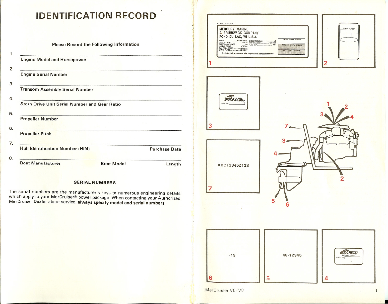
SPECIFICATIONS
Use extreme caution when operating in
• Cooling System - Inspect all hoses f shallow water or where underwater ob-
damage and deterioration; check all ho~ jects are known to be pre~~nt. Use
clamps for adequate tightness. extreme care to prevent stnklng sub-
merged objects while operating in RE-
VERSE. No impact protection is provided
in REVERSE.
17
• Before recovery. contact an Authorized
MerCruiser Dealer.
• After recovery, immediate service by
an Authorized MerCruiser Dealer is
required to prevent serious damage to
power package.
ATTENTION REQUIRED AFTER SUB-
MERSION
Boat can be trailered with drive unit in up
or down position. Adequate road clearance
is required between road and gear housing
skeg when trailering with drive unit in
down position.
TRAllERING BOAT
If adequate road clearance is a problem.
place drive unit in full trailer position and
support with an optional trailer kit which
is available from your Authorized Mer-
Cruiser Dealer.
• Starting and operating difficulties.
• Fuel permeation through flexible fuel
lines.
• Wear and damage of internal engine
parts.
The adverse effects of alcohol are more
severe with methyl alcohol (methanol)
and are worse with increasing alcohol
content.
Some of these adverse effects are due to
the tendency of gasolines containing
alcohol to absorb moisture from the air,
resulting in a phase of water and alcohol
separating from the gasoline in the fuel
tank.
MerCruiser V6/V8
If drive unit should strike a submerged
object, stop engine as soon as possible
and inspect drive unit for damage. If
damage is present or suspected, boat
should be taken to an Authorized Mer-
Cruiser Dealer for thorough inspection
and necessary repair. Operating a
damaged drive unit could cause additional
damage to other parts of drive unit, or
could affect control of boat. If continued
running is necessary, do so at greatly
reduced speeds.
IMPORTANT: Impact protection system
cannot be designed to ensure total pro-
tection from impact damage under all
conditions.
FUEL REQUIREMENTS
IMPORTANT: Use of improper gasoline
can cause severe engine damage. Engine
damage resulting from use of improper
gasoline is considered misuse of engine,
and damage caused thereby will not be
covered under the limited warranty.
The use of any good grade leaded regular,
unleaded regular or premium gasolines
with a minimum posted octane rating of
86 (research octane number 90), are satis-
factory for use in your engine. (High-
performance models are exceptions.) How-
ever, gasolines containing alcohol, either
methyl alcohol (methanol) or ethyl alcohol
(ethanol) may cause increased:
• Corrosion of metal parts.
• Deterioration of elastomer and plastic
parts.
• Check all fluid levels.
• Check carburetor adjustment.
• Inspect ignition system and timing.
• Check for loose, missing or damagel
parts.
• Check shift and throttle cable adjust
ments - lubricate and inspect for loose
damaged or missing parts.
• Steering System - Lubricate and in
spect for loose, damaged or missing parts
• Inspect all drive belts.
• Check engine alignment.
• Complete Engine Exhaust System .
Inspect for damage and deterioration;
check all hose clamps for adequate
tightness.
FREEZING TEMPERATURE OPERA-
TION
IMPORTANT: If boat is operated during
periods of freezing temperature. pre.
cautions must be taken to prevent
freezing damage to power package.
Refer to OUT OF SEASON STORAGE
for draining instructions.
DRIVE UNIT IMPACT PROTECTION
The Power Trim hydraulic system is
designed to provide impact protection for
drive unit. If a submerged object is struck
while boat is moving forward, the hy-
draulic system will cushion kickup of
drive unit as it clears the object, reducing
damage to unit. After drive unit has
cleared object, the hydraulic system
allows drive unit to return to original
operating position, preventing loss of
steering control and engine overspeed.
MerCruiser V6/V8
20-HOUR BREAK-IN PERIOD
IMPORTANT: The first 20 hours of
operation is the engine break-in period.
Correct break-in is essential to obtain
minimum oil consumption and maxi-
mum engine performance. During this
break-in period. the following rules
must be observed:
• Do not operate below 1500 RPM for
extended periods of time for first 10
hours. Shift into gear as soon as possible
after starting and advance throttle above
1500 RPM if conditions permit safe
operation.
• Do not operate at one speed con-
sistently for extended periods.
• Do not exceed 3/4 throttle during first
10 hours. During next 10 hours. occasional
operation at full throttle is permissible (5
minutes at a time maximum).
• Avoid full throttle acceleration from
IDLE speed.
• Do not operate at full throttle until
engine reaches normal operating temper-
ature.
• Frequently check crankcase oil level.
Add oil if needed. It is normal for oil
consumption to be high during break-in
period.
• After 20-hour break-in period, drain
crankcase oil and replace oil filter (see
MAINTENANCE). Fill crankcase with cor-
rect oil (see SPECIFICATIONS).
20-HOUR CHECKUP
After first 20 hours of operation, an
Authorized MerCruiser Dealer should be
contacted for the fOllowing maintenance.
The boat owner is responsible for any
charges.
• Change crankcase oil and filter.
16