Yamaha F150A User manual

F150A
FL150A
SERVICE MANUAL
63P-28197-3F-11
290503

NOTICE
This manual has been prepared by Yamaha primarily for use by Yamaha dealers and their trained
mechanics when performing maintenance procedures and repairs to Yamaha equipment. It has
been written to suit the needs of persons who have a basic understanding of the mechanical and
electrical concepts and procedures inherent in the work, for without such knowledge attempted
repairs or service to the equipment could render it unsafe or unfit for use.
Because Yamaha has a policy of continuously improving its products, models may differ in detail
from the descriptions and illustrations given in this publication. Use only the latest edition of this
manual. Authorized Yamaha dealers are notified periodically of modifications and significant
changes in specifications and procedures, and these are incorporated in successive editions of this
manual.
Important information 1
Particularly important information is distinguished in this manual by the following notations:
The Safety Alert Symbol means ATTENTION! BECOME ALERT! YOUR SAFETY IS
INVOLVED!
WARNING
Failure to follow WARNING instructions could result in severe injury or death to the machine
operator, a bystander, or a person inspecting or repairing the outboard motor.
CAUTION:
A CAUTION indicates special precautions that must be taken to avoid damage to the out-
board motor.
NOTE:
A NOTE provides key information to make procedures easier or clearer.
F150A, FL150A
SERVICE MANUAL
©2003 by Yamaha Motor Co., Ltd.
1st Edition, July 2003
All rights reserved.
Any reprinting or unauthorized use
without the written permission of
Yamaha Motor Co., Ltd.
is expressly prohibited.
Printed in the Netherlands

Contents
General information 1
GEN
INFO
Specifications 2
SPEC
Periodic checks and adjustments 3
CHK
ADJ
Fuel system 4
FUEL
Power unit 5
POWR
Lower unit 6
LOWR
Bracket unit 7
BRKT
Electrical systems 8
ELEC
Troubleshooting 9
TRBL
SHTG
Index
–+

GEN
INFO
63P3F11
General information
How to use this manual.................................................................................1-1
Manual format............................................................................................1-1
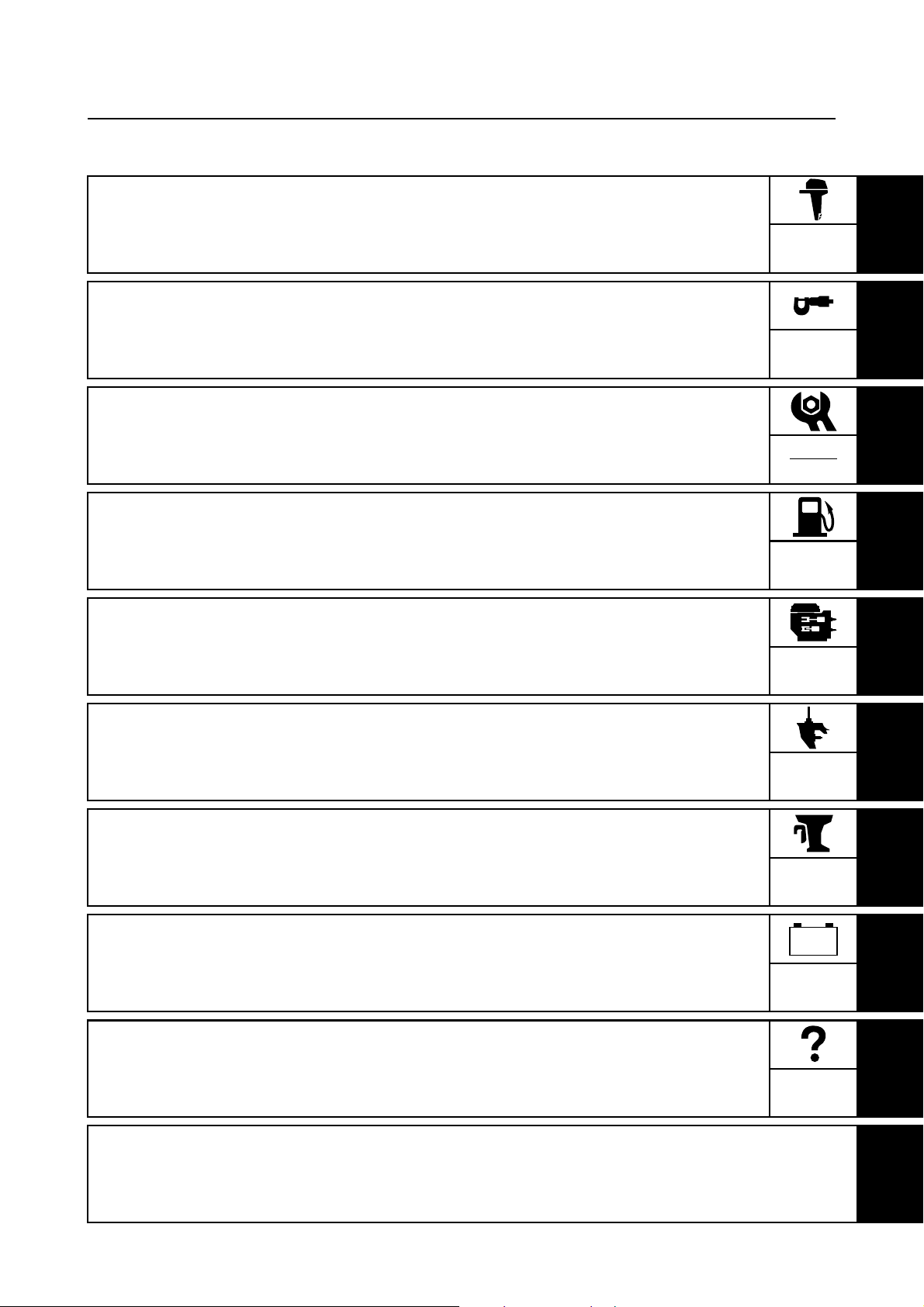
Symbols.....................................................................................................1-2
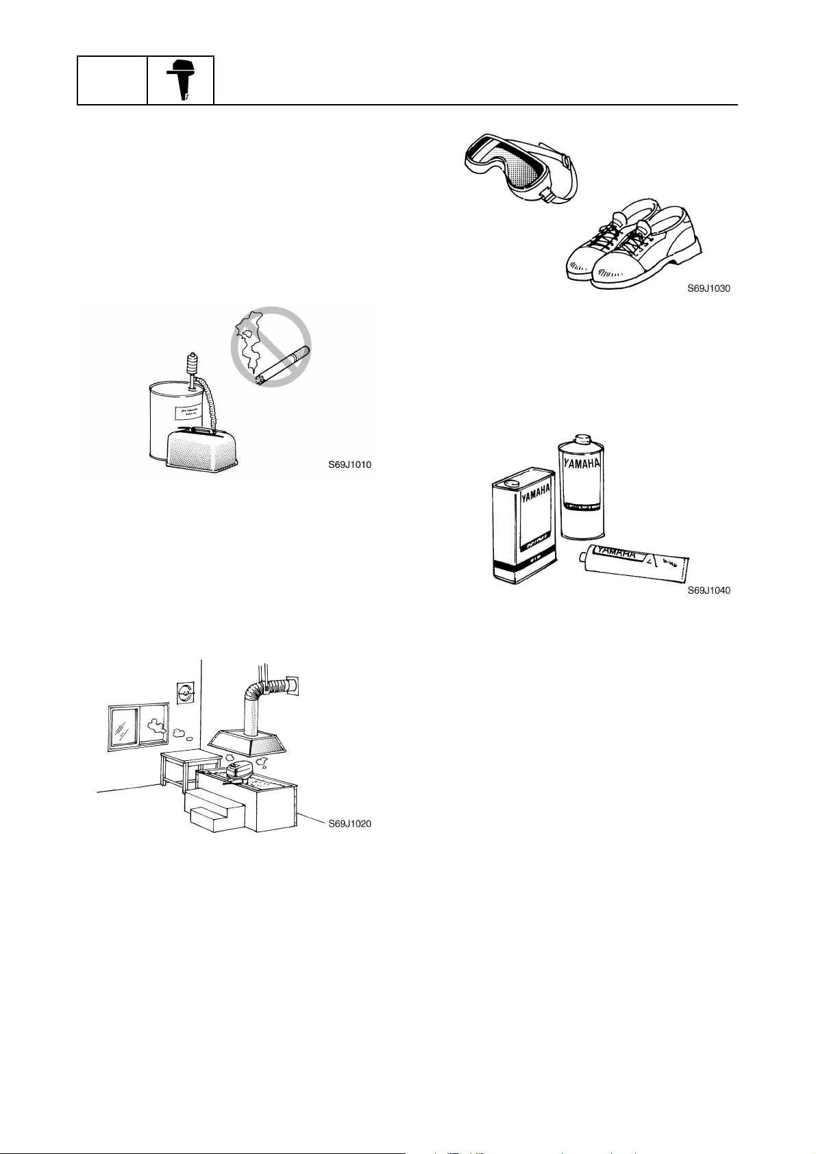
Safety while working......................................................................................1-3
Fire prevention...........................................................................................1-3
Ventilation..................................................................................................1-3
Self-protection ...........................................................................................1-3
Parts, lubricants, and sealants ..................................................................1-3
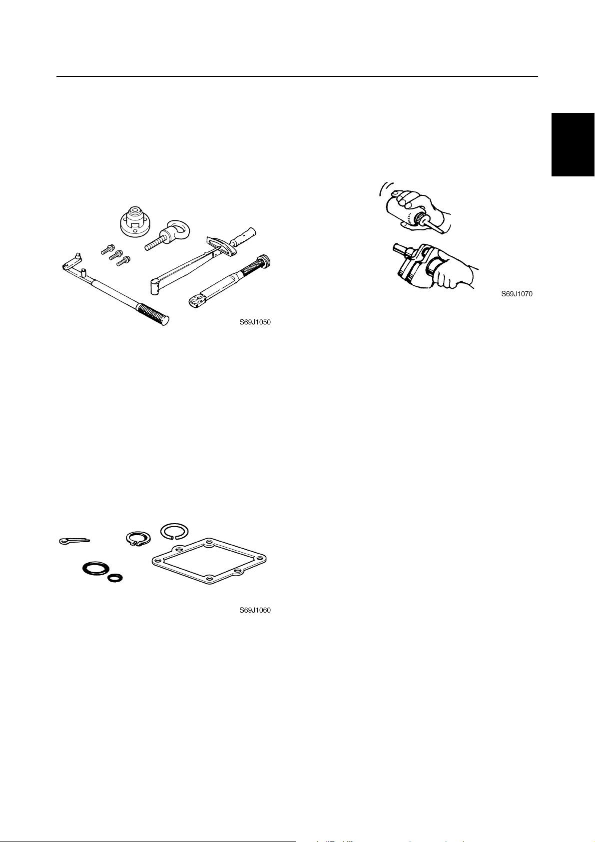
Good working practices .............................................................................1-4
Disassembly and assembly .......................................................................1-4
Identification...................................................................................................1-5
Applicable models .....................................................................................1-5
Serial number ............................................................................................1-5
Features and benefits....................................................................................1-6
Crankshaft and cylinder.............................................................................1-6
Balancer ....................................................................................................1-7
Piston and piston ring ................................................................................1-7
Connecting rod ..........................................................................................1-8
Cylinder head cover...................................................................................1-8
Intake system ............................................................................................1-9
Top cowling .............................................................................................1-10
64E type power trim and tilt unit ..............................................................1-11
Cooling system ........................................................................................1-12
Lubrication system...................................................................................1-13
Fuel system .............................................................................................1-15
Rectifier Regulator...................................................................................1-16
Isolator.....................................................................................................1-16
Technical tips ...............................................................................................1-17
Electronic control system.........................................................................1-17
ECM.........................................................................................................1-17
Fail-safe control .......................................................................................1-18
Warning control .......................................................................................1-19
Shift cut control........................................................................................1-20
Over-revolution control ............................................................................1-20
Fuel pump control....................................................................................1-20
Propeller selection.......................................................................................1-21
Propeller size...........................................................................................1-21
Selection..................................................................................................1-21

63P3F11
1
2
3
4
5
6
7
8
9
Predelivery checks ......................................................................................1-22
Checking the fuel system ........................................................................1-22
Checking the gear oil level ......................................................................1-22
Checking the engine oil level...................................................................1-22
Checking the battery................................................................................1-22
Checking the outboard motor mounting height........................................1-23
Checking the remote control cables ........................................................1-23
Checking the steering system .................................................................1-24
Checking the gear shift and throttle operation.........................................1-24
Checking the power trim and tilt system..................................................1-24
Checking the engine start switch and engine stop lanyard switch ..........1-24
Checking the cooling water pilot hole ......................................................1-25
Test run ...................................................................................................1-25
Break-in ...................................................................................................1-25
After test run ............................................................................................1-25

GEN
INFO General information
1-1 63P3F11
How to use this manual 1
Manual format
The format of this manual has been designed to make service procedures clear and easy to under-
stand. Use the information below as a guide for effective and quality service.
1Parts are shown and detailed in an exploded diagram and are listed in the components list.
2Tightening torque specifications are provided in the exploded diagrams and after a numbered
step with tightening instructions.
3Symbols are used to indicate important aspects of a procedure, such as the grade of lubricant
and lubrication point.
4The components list consists of part names and part quantities, as well as bolt and screw dimen-
sions.
5Service points regarding removal, checking, and installation are shown in individual illustrations
to explain the relevant procedure.
NOTE:
For troubleshooting procedures, see Chapter 9, “Troubleshooting.”
LOWR Lower unit
6-5 62Y5A11
Lower unit
No. Part name Q’ty Remarks
1 Lower unit 1
2 Plastic tie 1 Not reusable
3Hose 1
4 Check screw 1
5 Gasket 2 Not reusable
6 Dowel pin 2
7 Bolt 4 M10 40 mm
8 Drain screw 1
9Grommet 1
10 Bolt 1 M10 45 mm
11 Bolt 1 M8 60 mm
12 Thrust washer 1
13 Propeller 1
14 Washer 1
15 Washer 1
16 Cotter pin 1 Not reusable
17 Propeller nut 1
18 Trim tab 1
LOWR Lower unit
6-19 62Y5A11
Removing the drive shaft
1. Remove the drive shaft assembly and
pinion, and then pull out the forward
gear.
Disassembling the drive shaft
1. Install the pinion nut 1, tighten it finger
tight, and then remove the drive shaft
bearing 2using a press.
CAUTION:
•Do not press the drive shaft threads a
directly.
•Do not reuse the bearing, always
replace it with a new one.
Disassembling the forward gear
1. Remove the taper roller bearing from the
forward gear using a press.
CAUTION:
Do not reuse the bearing, always replace
it with a new one.
2. Remove the needle bearing from the for-
ward gear.
CAUTION:
Do not reuse the bearing, always replace
it with a new one.
Drive shaft holder 4 1: 90890-06518
Pinion nut holder 2: 90890-06505
Socket adapter 2 3: 90890-06507
Bearing inner race attachment 3:
90890-06639
S62Y6850K
Bearing separator 1: 90890-06534
Stopper guide plate 2: 90890-06501
Stopper guide stand 3:
90890-06538
Bearing puller 4: 90890-06535
Bearing puller claw 1 5:
90890-06536
S62Y6740K
5
4
321

63P3F11 1-2
1
2
3
4
5
6
7
8
9
Symbols
The symbols below are designed to indicate the content of a chapter.
General information
Specifications
Periodic checks and adjustments
Fuel system
Power unit
Lower unit
Bracket unit
Electrical systems
Troubleshooting
GEN
INFO
SPEC
CHK
ADJ
FUEL
POWR
LOWR
BRKT
ELEC
TRBL
SHTG
–+
Symbols 1to 6indicate specific data.
1Special tool
2Specified oil or fluid
3Specified engine speed
4Specified tightening torque
5Specified measurement
6Specified electrical value
(resistance, voltage, electric current)
Symbols 7to Cin an exploded diagram indicate the grade of lubricant and the lubrication point.
7Apply Yamaha 4-stroke motor oil
8Apply gear oil
9Apply water resistant grease (Yamaha grease A)
0Apply molybdenum disulfide grease
AApply corrosion resistant grease
(Yamaha grease D)
BApply low temperature resistant grease
(Yamaha grease C)
CApply injector grease
Symbols Dto Iin an exploded diagram indicate the type of sealant or locking agent and the appli-
cation point.
DApply Gasket Maker
EApply Yamabond No. 4
FApply LOCTITE 271 (red)
GApply LOCTITE 242 (blue)
HApply LOCTITE 572
IApply silicon sealant
123456
T
R
.
.
7890ABC
E G
A M
D
C I
DEFGHI
GM
4
271
LT
242
LT
572
LT SS
How to use this manual

GEN
INFO General information
1-3 63P3F11
Safety while working 1
To prevent an accident or injury and to
ensure quality service, follow the safety pro-
cedures provided below.
Fire prevention
Gasoline is highly flammable.
Keep gasoline and all flammable products
away from heat, sparks, and open flames.
Ventilation
Gasoline vapor and exhaust gas are heavier
than air and extremely poisonous. If inhaled
in large quantities they may cause loss of
consciousness and death within a short time.
When test running an engine indoors (e.g., in
a water tank) be sure to do so where ade-
quate ventilation can be maintained.
Self-protection
Protect your eyes by wearing safety glasses
or safety goggles during all operations involv-
ing drilling and grinding, or when using an air
compressor.
Protect your hands and feet by wearing pro-
tective gloves and safety shoes when neces-
sary.
Parts, lubricants, and sealants
Use only genuine Yamaha parts, lubricants,
and sealants or those recommended by
Yamaha, when servicing or repairing the out-
board motor.
Under normal conditions, the lubricants men-
tioned in this manual should not harm or be
hazardous to your skin. However, you should
follow these precautions to minimize any risk
when working with lubricants.
1. Maintain good standards of personal and
industrial hygiene.
2. Change and wash clothing as soon as
possible if soiled with lubricants.
3. Avoid contact with skin. Do not, for
example, place a soiled rag in your
pocket.
4. Wash hands and any other part of the
body thoroughly with soap and hot water
after contact with a lubricant or lubricant
soiled clothing has been made.
5. To protect your skin, apply a protective
cream to your hands before working on
the outboard motor.

63P3F11 1-4
1
2
3
4
5
6
7
8
9
6. Keep a supply of clean, lint-free cloths for
wiping up spills, etc.
Good working practices
Special service tools
Use the recommended special service tools
to protect parts from damage. Use the right
tool in the right manner—do not improvise.
Tightening torques
Follow the tightening torque specifications
provided throughout the manual. When tight-
ening nuts, bolts, and screws, tighten the
large sizes first, and tighten fasteners starting
in the center and moving outward.
Non-reusable parts
Always use new gaskets, seals, O-rings, cot-
ter pins, circlips, etc., when installing or
assembling parts.
Disassembly and assembly
1. Use compressed air to remove dust and
dirt during disassembly.
2. Apply engine oil to the contact surfaces
of moving parts before assembly.
3. Install bearings with the manufacture
identification mark in the direction indi-
cated in the installation procedure. In
addition, be sure to lubricate the bearings
liberally.
4. Apply a thin coat of water-resistant
grease to the lip and periphery of an oil
seal before installation.
5. Check that moving parts operate nor-
mally after assembly.
Safety while working

GEN
INFO General information
1-5 63P3F11
Identification 1
Applicable models
This manual covers the following models.
Serial number
The outboard motor serial number is
stamped on a label attached to the port
clamp bracket.
1Model name
2Approved model code
3Transom height
4Serial number
Applicable models
F150AET, FL150AET
Model name Approved
model code
Starting
serial No.
F150AET 63P L: 1000017–
X: 1000044–
FL150AET 64P L: 1000013–
X: 1000009–

63P3F11 1-6
1
2
3
4
5
6
7
8
9
Features and benefits 1
Crankshaft and cylinder
The center of the crankshaft is offset 10 mm (0.39 in) from the center of the cylinder to make more
space to incorporate the throttle body assembly.
This design produces good engine balance and allows a compact design.
Exhaust gas from each cylinder flows directly into the exhaust manifold to obtain a compact design
for the exhaust system.
1Throttle body assembly
2Oil/gas separator
3Direct exhaust system
4Rectifier Regulator
5Offset 10 mm (0.39 in)
6Balancer shafts
S63P1070
5
2
1
4
3
6
Identification / Features and benefits

GEN
INFO General information
1-7 63P3F11
Balancer
A two-piece balancer is used in the crankcase to reduce the secondary forces of inertia produced by
reciprocating pistons.
The balancer shaft 1 is driven by the gear on the crankshaft.
The balancer shaft 2 is driven by the gear on the balancer shaft 1.
The two counterrotating balancer shafts rotate at twice the speed of the crankshaft and reduce the
forces of inertia of the connecting rods and each balancer shaft.
Therefore, engine vibration is reduced.
1Balancer shaft 1
2Balancer shaft 2
3Piston secondary force of inertia
4Balancer force of inertia
Piston and piston ring
A forged piston has been adopted for durability.
Hard chromium plating is applied to the piston rings.
The top and 2nd piston rings differ and are identified by a mark on each ring.
Install the piston rings on the piston with the identification marks facing up.
1Top ring
22nd ring
3Upper oil ring rail
4Lower oil ring rail
S63P1080
1
2
3
4
S63P1090
4
5
˚
12
RRN
4
5
˚
3
1
2
4

63P3F11 1-8
1
2
3
4
5
6
7
8
9
Connecting rod
A direction mark for installing the connecting rod to the crankshaft in the proper direction is on the
connecting rod cap.
The direction mark should face the flywheel.
The connecting rod and connecting rod cap are manufactured as a single piece. Then, they are split
using impact force. Only use the connecting rods and connecting rod caps in their original combina-
tions, do not interchange them.
1Direction mark
Cylinder head cover
The oil/gas separator is used to obtain low emissions and is built into the cylinder head cover to
obtain a compact design.
The gas and oil flow is shown below.
1Intake silencer
2Cylinder head cover (with gas/oil separator)
ÈBlowby gas
ÉOil
S63P1100
1
S63P1110
:
È
:
É
1
2
Features and benefits

GEN
INFO General information
1-9 63P3F11
Intake system
Multi-point, group fuel injection with four separate throttle valves is adopted for the intake system.
Intake air volume is calculated according to engine speed, Intake air pressure, and throttle position,
and then the fuel injection volume is determined by the intake air volume to obtain a precise air and
fuel ratio under all operating conditions.
The cylinders are grouped, #1/#4 and #2/#3. Fuel is injected twice during each full cycle of each cyl-
inder, once during the exhaust stroke and once during the compression stroke. Fuel is injected dur-
ing the compression stroke of the #1 cylinder and the exhaust stroke of the #4 cylinder and during
the exhaust stroke of the #1 cylinder and the compression stroke of the #4 cylinder. The same
occurs during the compression and exhaust strokes of the #2 and #3 cylinders.
This allows a simpler fuel injection control system.
1Four separate throttle valve
S63P1120
1
Initial injection timing
BTDC10
#1 cylinder
Compression Combustion
Exhaust Intake
#3 cylinder
Intake
Compression Combustion
Exhaust
#4 cylinder
Exhaust Intake
Compression Combustion
#2 cylinder
Combustion
Exhaust Intake
Compression

63P3F11 1-10
1
2
3
4
5
6
7
8
9
The shape of the fuel injectors is the same for the F115, F150, F200 and F225.
Therefore, each fuel injector is identified by color because the specifications of each fuel injector are
different.
ÈModel
ÉInjector color
ÊFirst three digits
ËOrange
ÌYellow
ÍIvory
Top cowling
Water is separated from the intake air and flows down through the drain hoses before draining out
through the bottom cowling.
The structure of the top cowling helps to prevent water from accumulating in the top cowling and
entering the power unit.
1Water separator
2Air (including water)
3Drain hoses
ÈWater
S63P1130
ÈÉ
Ë
Í
Ê
F115 732
F150 731
F200 741
F225
Ì
S63P1140
3
1
2
: È
Features and benefits

GEN
INFO General information
1-11 63P3F11
64E type power trim and tilt unit
The 64E type clamp bracket and power trim and tilt unit used for current V4 and V6 outboard motors
have been adopted.
This allows easier interchanging of Yamaha outboards with the same classification because the
mounting dimensions are the same.
For the power trim and tilt unit, only the impact absorber valve opening pressure of the tilt piston
fluid circuit has been changed. The pressure is distinguished from those of other models by an iden-
tification mark stamped on the power trim and tilt unit.
È
S63P1150
È
Identification mark Applicable models
YA Carbureted V4 and V6 (2.6)
YB N/A
YC Electronic fuel injected V6 (2.6), HPDI (2.6),
VX200 (200H), VX225 (225G), and VX250 (250C)
YD F115 (F115A), LF115 (FL115A), and (F100B)
YE VZ225 (Z225H) and VZ250 (Z250F)
YF F150 (F150A) and LF150 (FL150A)

63P3F11 1-12
1
2
3
4
5
6
7
8
9
Cooling system
The cooling water flow diagram is as follows.
To cool the propeller damper, the cooling system is designed so that fresh cooling water is taken in
from the front of the trim tab and supplied to the exhaust passage of the lower case to cool the
exhaust gas.
Cooling water also accumulates around the exhaust muffler to cool the upper case and reduce
exhaust noise.
1Exhaust manifold
2Muffler
3Exhaust gas
4Water
ÈWater
S63P1170
Thermostat
Cylinder block
Cylinder head
Cylinder block
Exhaust cover
Exhaust guide
Oil pan
Water pump
Water inlet
Sea / River / Lake
Pressure control valve
Upper case
Lower case
Propeller boss
Trim tab
Cooling water pilot hole
Fuel cooler
:
È
1
2
3
4
Features and benefits

GEN
INFO General information
1-13 63P3F11
Lubrication system
The lubrication oil flow diagram is as follows.
There is a small hole in the relief valve to allow oil to drain from the oil filter bracket so that it does
not remain in the oil filter. This prevents oil from spilling out when replacing the oil filter.
1Relief valve
2Oil filter bracket
ÈOil
S63P1260
Cylinder sleeve
Piston
Crankpin
Balancer
journal
Crankshaft main journal
Main passage
Oil filter
Oil filter bracket
Relief valve
Oil pump
Oil strainer
Oil pan
Camshaft journal
Camshaft
IN/EX valve
Oil pressure sensor
Crankcase Cylinder head
S63P1180
:
È
12

63P3F11 1-14
1
2
3
4
5
6
7
8
9
A dual oil drain system is adopted.
An oil drain bolt is located on the bottom of the oil pan.
A long dipstick guide, which reaches the bottom of the oil pan, can also be used to pump out the oil
completely with an oil-extracting tool.
1Drain bolt
2Dipstick guide
S63P1190
1
2
Features and benefits

GEN
INFO General information
1-15 63P3F11
Fuel system
A fuel pressure regulator is incorporated onto the outlet of the electric fuel pump to obtain a compact
design and simple fuel delivery.
Fuel discharged from the pressure regulator returns to the vapor separator after being cooled in the
fuel cooler.
The pressure check valve is incorporated onto the fuel rail for easier servicing of the fuel system.
1Pressure regulator
2Vapor separator
3Fuel cooler
ÈFuel flow
S63P1200
Fuel tank
Vapor separator Electric fuel pump Fuel rail
Primer pump Fuel filter
(69J type)
Pressure
check valve
Fuel cooler
Pressure regulator
Fuel
injector
Fuel
injector
Fuel
injector
Fuel
injector
12 34
Fuel filter (fuel tank) Fuel pump
: È
3
2
1
Other manuals for F150A
2
This manual suits for next models
1
Table of contents
Other Yamaha Outboard Motor manuals

Yamaha
Yamaha DE-DHT User manual

Yamaha
Yamaha VF115 User manual

Yamaha
Yamaha VZ175 User manual

Yamaha
Yamaha 40C User manual

Yamaha
Yamaha VZ225B User manual

Yamaha
Yamaha e60hwd User manual

Yamaha
Yamaha FL250A User manual

Yamaha
Yamaha 40V User manual

Yamaha
Yamaha D150W User manual

Yamaha
Yamaha 160 6V User manual