Mercury/Mariner 25 MARATHON User manual

MODELS
United States 0G044027 and Above. . . . . . .
Belgium 09807909 and Above. . . . . . . . . . .
With Serial Numbers
SERVICE
MANUAL
20 JET 20 25
Mercury/Mariner
25 MARATHON 25 SEAPRO
Printed in U.S.A. 1998, Mercury Marine 90-826883R2 JUNE 1998
90-826883R2 JUNE 1998 Page i
Notice
Throughoutthispublication,“Dangers”,“Warnings”and“Cautions”(accompaniedbytheIn-
ternationalHAZARDSymbol )areusedtoalertthemechanictospecialinstructionscon-
cerning a particular service or operation that may be hazardous if performed incorrectly or
carelessly. OBSERVE THEM CAREFULLY!
These“SafetyAlerts”alonecannoteliminatethehazardsthattheysignal.Strictcompliance
tothesespecialinstructionswhenperformingtheservice,plus“CommonSense”operation,
are major accident prevention measures.
DANGER
DANGER- Immediatehazards whichWILL resultin severepersonal injuryor death.
WARNING
WARNING - Hazards or unsafe practices which COULD result in severe personal in-
jury or death.
CAUTION
Hazards or unsafe practices which could result in minor personal injury or product
or property damage.
Notice to Users of This Manual
This service manual has been written and published by the Service Department of Mercury
Marine to aid our dealers’ mechanics and company service personnel when servicing the
products described herein.
It is assumed that these personnel are familiar with the servicing procedures of these prod-
ucts, or like or similar products manufactured and marketed by Mercury Marine, that they
have been trained in the recommended servicing procedures of these products which in-
cludestheuseofmechanics’commonhandtoolsandthespecialMercuryMarineorrecom-
mended tools from other suppliers.
We could not possibly know of and advise the service trade of all conceivable procedures
by which a service might be performed and of the possible hazards and/or results of each
method. We have not undertaken any such wide evaluation. Therefore, anyone who uses
a service procedure and/or tool, which is not recommended by the manufacturer, first must
completelysatisfyhimselfthatneitherhis nor the products safety will be endangered by the
service procedure selected.
All information, illustrations and specifications contained in this manual are based on the
latest product information available at the time of publication. As required, revisions to this
manual will be sent to all dealers contracted by us to sell and/or service these products.
Itshouldbekeptinmind,whileworkingontheproduct,thattheelectricalsystemandignition
systemarecapableofviolentanddamagingshortcircuitsorsevereelectricalshocks.When
performing any work where electrical terminals could possibly be grounded or touched by
the mechanic, the battery cables should be disconnected at the battery.
Anytimetheintakeorexhaustopeningsareexposedduringservicetheyshouldbecovered
toprotectagainstaccidentalentranceofforeignmaterialwhichcouldenterthecylindersand
cause extensive internal damage when the engine is started.
Page ii 90-826883R2 JUNE 1998
Itisimportanttonote,duringanymaintenanceprocedurereplacementfastenersmusthave
thesamemeasurementsandstrengthasthoseremoved.Numbersontheheadsofthemet-
ricbolts and on the surfaces of metric nuts indicatetheirstrength.Americanbolts use radial
lines for this purpose, while most American nuts do not have strength markings. Mis-
matched or incorrect fasteners can result in damage or malfunction, or possibly personal
injury.Therefore,fastenersremovedshouldbesavedforreuseinthesamelocationswhen-
ever possible. Where the fasteners are not satisfactory for re-use, care should be taken to
select a replacement that matches the original.
Cleanliness and Care of Outboard Motor
A marine power product is a combination of many machined, honed, polished and lapped
surfaces with tolerances that are measured in the ten thousands of an inch/mm. When any
product component is serviced, care and cleanliness are important. Throughout this manu-
al, it should be understood that proper cleaning, and protection of machined surfaces and
friction areas is a part of the repair procedure. This is considered standard shop practice
even if not specifically stated.
Whenever components are removed for service, they should be retained in order. At the
timeofinstallation, they should be installed in the same locations and withthesame mating
surfaces as when removed.
Personnelshouldnot work on or under an outboard which is suspended. Outboards should
be attached to work stands, or lowered to ground as soon as possible.
We reserve the right to make changes to this manual without prior notification.
Refer to dealer service bulletins for other pertinent information concerning the products de-
scribed in this manual.
Page Numbering
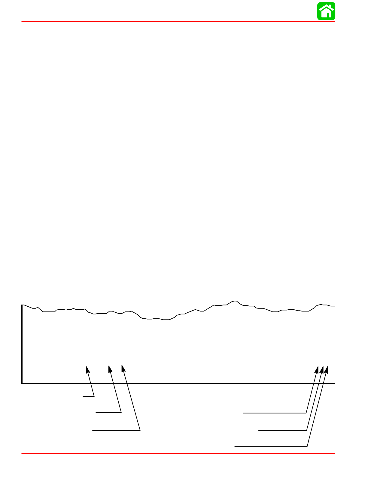
Twonumbergroupsappearatthebottomofeachpage.Theexamplebelowisself-explana-
tory.
EXAMPLE:
90-826883 R2 JUNE 1998 6A-7
Revision No. 2
Month of Printing
Year of Printing
Section Number
Part of Section Letter
Page Number

1
2
3
4
5
6
7
8
9
Important Information
Electrical
Fuel System
Powerhead
Mid-Section
Lower Unit
Attachment/Control Linkage
Manual Starter
90-826883R2 JUNE 1998 Page iii
Service Manual Outline
Section 1 - Important Information
A - Specifications
B - Maintenance
C - General Information
D - Outboard Installation
Section 2 - Electrical
A - Ignition
B - Charging & Starting System
C - Timing, Synchronizing & Adjusting
D - Wiring Diagrams
Section 3 - Fuel System
A - Carburetor/Fuel Pump
B - Emissions
Section 4 - Powerhead
Section 5 - Mid-Section
Section 6 - Lower Unit
A - Gear Housing
B - Jet Drive
Section 7 - Attachments/Control Linkage
A - Throttle/Shift Linkage
B - Tiller Handle
C - Side Shift
Section 8 - Manual Starter

1
A
SPECIFICATIONS
90-826883R2 JUNE 1998 Page 1A-1
IMPORTANT INFORMATION
Section 1A - Specifications
Table of Contents
Master Specifications 1A-2. . . . . . . . . . . . . . . . . . . . . . . . .
SPECIFICATIONS
Page 1A-2 90-826883R2 JUNE 1998
Master Specifications
Model 15XD/20 Jet /20/25
HORSEPOWER
(KW) Model 20 Jet
Model 20
Model 25
20 (14.9)
20 (14.9
25 (18.7)
OUTBOARD
WEIGHT 15 in. (38 cm)
20 in. (51 cm)
20 Jet
114 lbs - 52 kg
117 lbs - 53 kg
124 lbs - 56 kg
CYLINDER
BLOCK Type
Displacement Two Cylinder - Two Cycle
24.4 cu. in. (400 cc)
STROKE Length 2.362 in. (60 mm)
CYLINDER
BORE Diameter (Standard)
Taper/Out of Round Maximum*
Bore Type:
S/N 0G202749 and Below
S/N 0G202750 and Above
2.562 in. (65.01 mm)
0.003 in. (0.08 mm)*
Chrome
Mercosil
CRANK SHAFT Top Main Bearing Journal
Center Main Bearing Journal
Bottom Main Bearing Journal
Connecting Rod Journal
End Play
1.251 in. (31.77 mm)
1.000 in. (25.40 mm)
1.125 in. (28.58 mm)
0.883 in. (22.43 mm)
0.004-0.019 (0.10-0.64 mm)
CONNECTING
ROD Piston Pin End (I.D.)
Crankpin End (I.D.) 0.897 in. (22.78 mm)
1.196 in. (30.38 mm)
PISTON Piston Type
O.D. at Skirt (Standard)
Ring End Gap
Aluminum
2.5583 - 2.5593 (64.98 - 65.00)
0.011-0.025 (.28 mm - .64 mm)
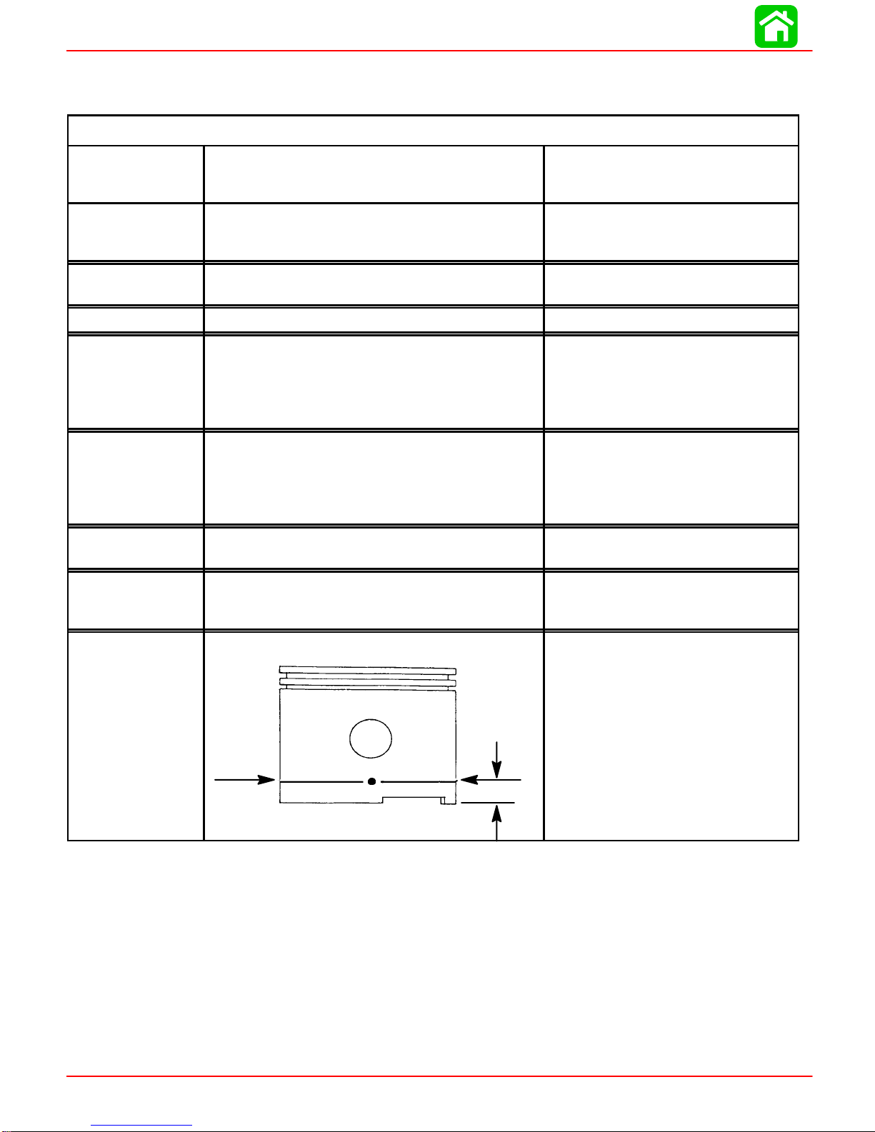
PISTON DIA.
Dimension “A”
at Right Angle
(90°) to Pis-
ton Pin 0.50 in.
(12.7 mm)
2.5583 in. ±.0005 in.
(64.98 mm ±.0127 mm)Using a
micrometer, measure dimension
“A” at location shown. Dimension
“A” should be 2.5583 in. ±.0005 for
a STANDARD size piston (new) Di-
mension “A” will be 0.001 – 0.0015
less if coating is worn off piston
(used)
*Models S/N 0G202749 and Below:
NOTE: The cylinder bores are chrome and cannot be be rebored or efficiently honed.
Checkeachcylinderbore foranout-of-round “eggshaped”cylinder.Amaximumof0.003
in. (0076mm) is allowable.
*Models S/N 0G202750 and Above:
NOTE: The cylinder block is Mercosil and the cylinders can be rebored to 0.030 in. over-
sized. Check each cylinder bore for an out-of-round “egg shaped” cylinder. A maximum
of 0.003 in. (0.076mm) is allowed.

SPECIFICATIONS
90-826883R2 JUNE 1998 Page 1A-3
Master Specifications
GEAR
HOUSING Forward - Neutral - Reverse
Gear Ratio
Gearcase Capacity
Lubricant Type
Forward Gear - No. of Teeth-Type
Pinion Gear - No. of Teeth-Type
Pinion
Foreword Gear Backlash
Reverse Gear Backlash
Water Pressure @ RPM
Water Pressure With 120°Thermostat
Full Shift
2.25:1
8.8 fl.oz. (260 ml)
Quicksilver Gear Lube Premium
Blend
27
12
Not Adjustable
Not Adjustable
Not Adjustable
2-7 PSI @ 2000 RPM
0-6 PSI (SPORADIC) 2000 RPM
MID
SECTION Transom Height - Short Shaft
- Long Shaft 15 in. (38 cm)
20 in. (51 cm)
FUEL
SYSTEM Fuel Pump Type
Recommended Gasoline
Fuel Tank Capacity
Operating Fuel/Oil Ratio
Integral
Automotive Unleaded
with a Minimum Pump Posted
Octane Rating of 87
6.6 U.S. Gallons
50:1
OIL Recommended Oil (Pre-Mix @ 50:1) NMMA TC-W II or TC-W III
2-Cycle Outboard Oil
STARTING
SYSTEM Manual Start
Rope Length
Electric Start
Ampere Draw (cranking)
Recoil
66 in. (1676 mm)
12 Volt
55 amperes
CHARGING
SYSTEM Alternator Output
BLACK Stator - 2 Magnet Flywheel
(8 Pole)(4 Pulses)
RED Stator - 4 Magnet Flywheel
(10 Pole)(5 Pulses)
4 Amp. (48 Watt)
@ 6000 RPM
6 amp (72 Watt)
@ 6000 RPM
BATTERY Battery Rating 465 Marine Cranking Amps (MCA)
or 350 Cold Cranking Amps (CCA)

SPECIFICATIONS
Page 1A-4 90-826883R2 JUNE 1998
IGNITION
SYSTEM
Readings taken @
68°F (20°C).
Type
Spark Plug Type (NGK)
Spark Plug Gap
Spark Plug Hex
Firing Order
20 Jet 19941/2THRU 1998
20/25 19941/2THRU 1996
Electronic Spark Advance
Idle @ 750 ±50 RPM (In Forward
Gear)
Fast Idle Speed
Maximum BTDC (Running)
Setup Timing
Stator High Speed Winding
Stator Low Speed Winding
Diode Test
Ignition Coil Resistance:
Primary
Secondary (w/o Boots)
20 Jet 1999 and Newer
20/25 1997/98 Models
Mechanical Spark Advance
Idle @ 750 ±50 RPM (In Forward
Gear)
Fast Idle Speed
Maximum BTDC (Running)
Stator High Speed Winding
Stator Low Speed Winding
Diode Test
Ignition Coil Resistance:
Primary
Secondary (w/o Boots)
Trigger
Capacitor Discharge Ignition
NGK BP8H-N-10
0.040 in. (1.0 mm)
18 mm
1-2
4°±2°B.T.D.C (Not Adjustable)
1400 RPM ±250 RPM
25°±1 @5500 RPM
28°B.T.D.C. @ 3000 ±200 R.P.M.
(Set-up timing of 28°B.T.D.C. will
be retarded to 25°B.T.D.C. @
5500 R.P.M.)
100 – 180 Ω (RED – BLK)
2900 – 3500 Ω (BLUE – BLACK)
2800 – 3400 Ω (RED – BLUE)
0 Ω
850 – 1200 Ω
6°±1°B.T.D.C
1500 RPM ±200 RPM
25°±1 @5500 RPM
120 - 180 Ω(BLK/WHT - GRD)
3200 - 3800 Ω(BLK/YEL - GRD)
3100 – 3700 Ω(BLK/YEL - BLK/
WHT)
0.02 - 0.04 Ω
8000 - 11000 Ω
6500 - 8500 Ω
JET DRIVE Impeller Liner Clearance 0.030 in. (0.8 mm)
* Use NGK BPZ8H-N-10 Where Radio Frequency Interference (RFI) Suppression is
Required.

SPECIFICATIONS
90-826883R2 JUNE 1998 Page 1A-5
Master Specifications
CARBURETOR
SPECIFI-
CATIONS
Idle RPM (In Forward Gear)
Wide Open Throttle (WOT) RPM
20
25
Idle Mixture Screw
Adjustment (Preset-Turns Out)
20
20 Jet
25/25 Seapro/25 Marathon
Float Level
Main Jet Size
19941/2thru 1996
-20 (WMC-44)
-25/20 Jet (WMC-45)
-25 Seapro/Marathon (WMC-46)
-25 Seapro/Marathon (WMC-46A)
1997 and Newer
-20 Jet (WMC-45)
-20 (WMC-52)
-25 (WMC-53)
-25 Seapro/Marathon (WMC-54)
750 ±50
4500 - 5500
5000 - 6000
1 ±1/4 Turn
1-1/2 ±1/2 Turn
1-1/4 ±1/4 Turn
1.0 in. (25.4 mm)
0.044 in. (1.12 mm)
0.076 in. (1.93 mm)
0.076 in. (1.93 mm)
0.080 in. (2.03 mm)
0.076 in. (1.93 mm)
0.044 in. (1.12 mm)
0.076 in. (1.93 mm)
0.080 in. (2.03 mm)
TIMING
SPECIFI-
CATIONS
20 Jet 19941/2THRU 1998
20/25 19941/2THRU 1996
Electronic Spark Advance
Idle @ 750 ±50 RPM (In Forward
Gear)
Fast Idle Speed
Maximum BTDC (Running)
Setup Timing
20/25 1997 AND NEWER
20 Jet 1999 AND NEWER
Mechanical Spark Advance
Idle @ 750 ±50 RPM (In Forward
Gear)
Fast Idle Speed
Maximum BTDC (Running)
4°±2°B.T.D.C (Not Adjustable)
1400 RPM ±250 RPM
25°±1 @5500 RPM
28°B.T.D.C. @ 3000 ±200 R.P.M.
(Set-up timing of 28°B.T.D.C. will
be retarded to 25°B.T.D.C. @
5500 R.P.M.)
6°±1°B.T.D.C
1500 RPM ±200 RPM
25°±1 @5500 RPM
1
B
MAINTENANCE
90-826883R2 JUNE1998 Page 1B-1
IMPORTANTINFORMATION
Section 1B-Maintenance
TableofContents
Table ofContents1B-1............................
Specifications1B-1...............................
GearCase LubricantCapacity1B-1..............
SpecialTools1B-1.............................
QuicksilverLubricant/Sealant1B-2...............
Inspection and MaintenanceSchedule 1B-3..........
BeforeEachUse 1B-3.........................
AfterEachUse 1B-3...........................
Every100 HoursofUse orOnceYearly,
WhicheverOccursFirst1B-3....................
Every300 HoursofUse orThree Years1B-3......
Flushing The Cooling System1B-4.................
FuelSystem1B-5................................
FuelLine Inspection 1B-5.......................
Engine FuelFilter1B-5.........................
Corrosion ControlAnode 1B-6.....................
SparkPlug Inspection 1B-7........................
BatteryInspection 1B-7...........................
FuseReplacement-- ElectricStartRemote
ControlModels1B-8..............................
Lubrication Points1B-8...........................
GearCase Lubrication 1B-10......................
GearCase LubricantCapacity1B-10.............
Draining GearCase 1B-10......................
Draining GearCase 1B-11......................
Checking LubricantLeveland Refilling
GearCase 1B-11..............................
Storage Preparations1B-12.......................
FuelSystem1B-12............................
Protecting ExternalEngine Components1B-12....
Protecting InternalEngine Components1B-12.....
GearCase 1B-13..............................
Positioning OutboardforStorage 1B-13..........
BatteryStorage 1B-13.........................
Specifications
GearCase LubricantCapacity
Gear Case Ratio Capacity
2.25:1 8.8fl.oz.(260.0ml)
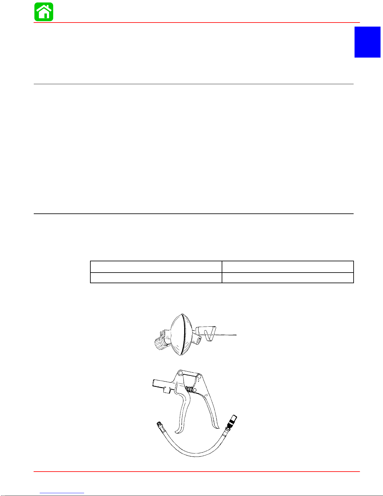
SpecialTools
1.Flushing Attachment44357A2
2.GreaseGun 91-37299A1

MAINTENANCE
Page 1B-2 90-826883R2 JUNE1998
QuicksilverLubricant/Sealant
1.QuicksilverAnti-Corrosion GreaseP/N92-78376A6
2.2-4-CMarine LubricantwithTeflon P/N92-825407A12
3.SAE 30WMotorOil P/N92-97959
4.QuicksilverGearLubricantP/N92-19007A24

MAINTENANCE
90-826883R2 JUNE1998 Page 1B-3
Inspection and Maintenance Schedule
BeforeEachUse
1.Check thatlanyardstop switchstopsthe engine.
2.Visuallyinspect the fuelsystemfordeterioration orleaks.
3.Check outboardfortightness on transom.
4.Check steering systemforbinding orloosecomponents.
5.Visually check steering linkrod fastenersforpropertightness.
6.Check propellerbladesfordamage.
AfterEachUse
1.Flush out the outboardcooling systemifoperating insaltorpolluted water.
2.Wash off all saltdepositsand flush out the exhaustoutletof the propellerand gear
casewithfreshwaterifoperating insaltwater.
Every 100 HoursofUse orOnce Yearly,WhicheverOccursFirst
1.Lubricate all lubrication points.Lubricatemorefrequentlywhen used insaltwater.
2. Inspectand clean sparkplugs.
3.Check fuel line filterforcontaminants.
4.Check carburetoradjustments,ifrequired.
5.Check corrosion controlanodes.Check morefrequentlywhen used insaltwater.
6.Drain and replace gearcaselubricant.
7.Lubricatesplineson the driveshaft.*
8.Electric startmodels-- Inspectbattery.
9.Remotecontrolmodels-- Check controlcable adjustments.*
10.Remove engine depositswithQuicksilverPowerTune Engine Cleaner.
11.Check tightness ofbolts,nuts,and otherfasteners.
12.Clean fueltankpick up filter.
Every 300 HoursofUse orThree Years
1.Replacewaterpumpimpeller (more often ifoverheating occursor reduced water
pressureisnoted).*
*Theseitems should be serviced byan authorized dealer.
MAINTENANCE
Page 1B-4 90-826883R2 JUNE1998
Flushing TheCooling System
Flushthe internalwaterpassagesof the outboardwithfreshwateraftereach useinsalt,
polluted,ormuddywater.Thiswill help preventa buildup ofdepositsfromclogging the
internalwaterpassages.
Use a Quicksilveraccessory(orequivalent)flushing attachment.
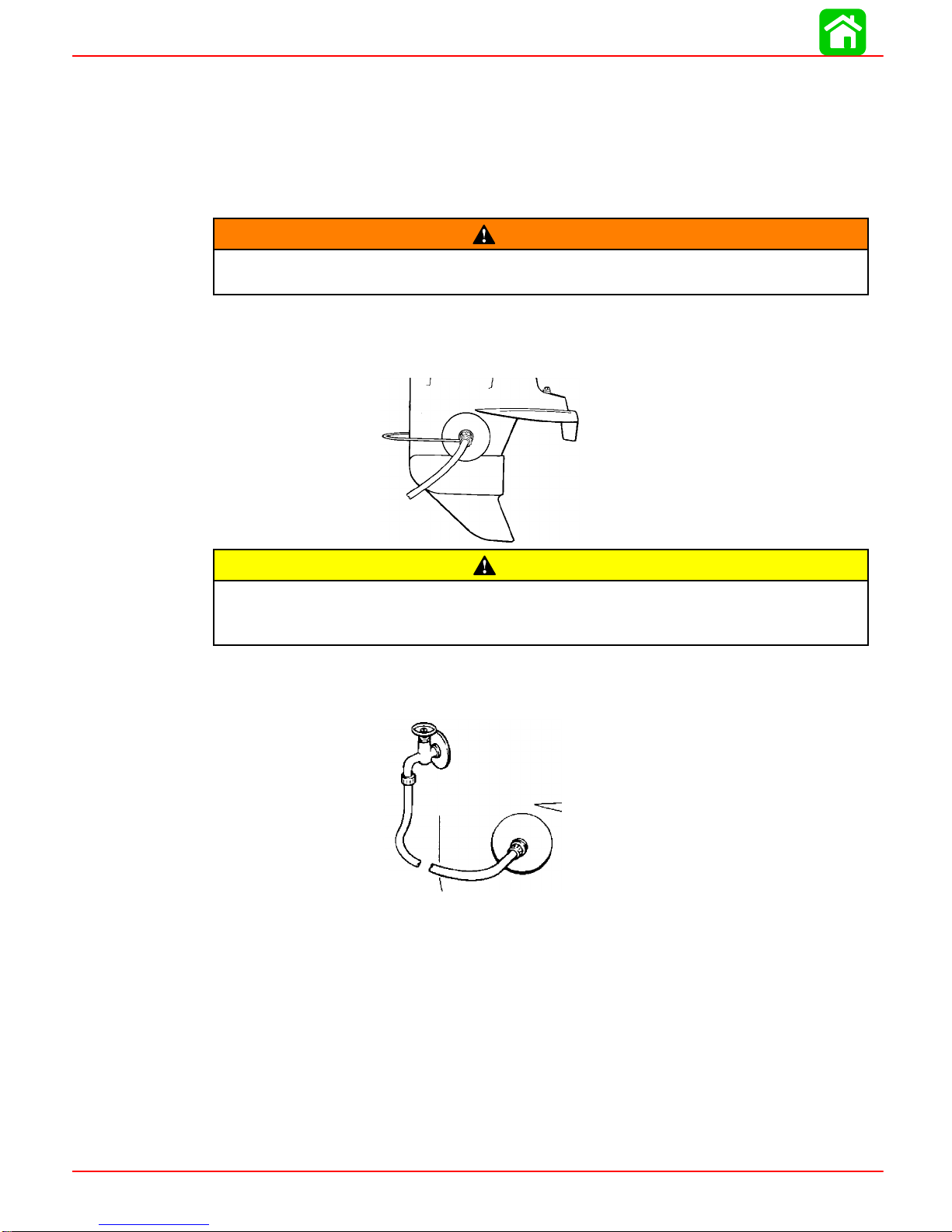
WARNING
To avoid possibleinjurywhenflushing,remove thepropeller.RefertoPropeller
Replacement.
1.Removepropeller(refertoPropellerReplacement).Installtheflushingattachmentso
the rubbercupsfit tightlyoverthe cooling waterintake holes.
CAUTION
Neverstartor run youroutboard(evenmomentarily)withoutwatercirculating
through the cooling waterintake inthegearcase to preventdamagetothewater
pump(running dry)oroverheating of the engine.
2.Attachawaterhosetothe flushingattachment. Turn on thewaterandadjust theflow
sowaterisleakingaroundtherubbercupstoensuretheenginereceivesanadequate
supplyofcooling water.
3.Start the engine and run itatidlespeed in neutralshift position.

MAINTENANCE
90-826883R2 JUNE1998 Page 1B-5
4.Adjustwaterflow(ifnecessary)so excess watercontinuesleaking out fromaround
therubbercupstoensuretheengineisreceivinganadequatesupplyofcoolingwater.
5.Checkforasteadystreamofwaterflowingoutof thewaterpumpindicatorhole.Con-
tinue flushing the outboardfor3to 5 minutes,carefullymonitoring watersupplyatall
times.
6.Stoptheengine,turnoffthe water,andremovethe flushing attachment. Reinstallthe
propeller.
FuelSystem
WARNING
Avoidseriousinjuryordeathfromgasolinefireorexplosion.Carefullyfollowall
fuelsystemservice instructions.Always stop the engine and DONOTsmoke or
allowopenflames orsparks inthe area while servicing anypartof thefuelsys-
tem.
Beforeservicinganypartofthefuelsystem,stopengineanddisconnectthebattery.Drain
the fuelsystemcompletely.Use an approved containertocollectand storefuel.Wipe up
any spillage immediately.Materialused tocontainspillage mustbe disposed ofin an ap-
proved receptacle.Anyfuelsystemservicemustbe performed in a well ventilated area.
Inspectany completed serviceworkforsign of fuel leakage.
FuelLineInspection
Visuallyinspectthefuellineandprimerbulbforcracks,swelling,leaks,hardnessorother
signsofdeteriorationordamage.Ifanyoftheseconditionsisfound,thefuellineorprimer
bulbmustbe replaced.
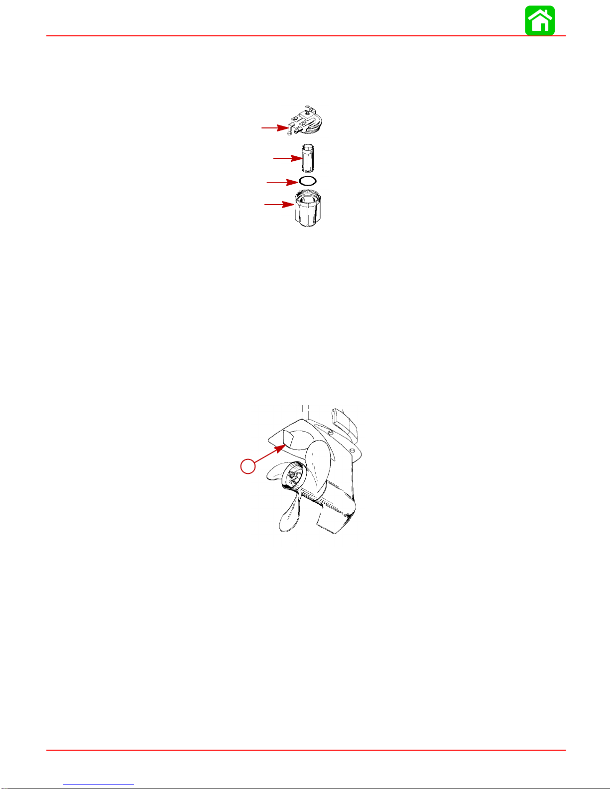
EngineFuelFilter
Inspectthesightbowlforwateraccumulationandinspect the filterelement forsediment.
Clean filterasfollows.
REMOVAL1.Hold ontothe coverto preventit fromturning.
2.Turn off the sightbowl.
3.Pull out the filterelementand washitwithcleaning solvent.
MAINTENANCE
Page 1B-6 90-826883R2 JUNE1998
INSTALLATION1.Pushthe filterelement(with open end towardcover) intocover.
2.Placethe O-ring seal intothe sightbowland screwthe sightbowlhand tightintothe
cover.
2
3/4
5
1
3.Visuallyinspect forfuel leakage around the sightbowlby squeezing the primerbulb
until firm, forcing fuel intothe sightbowl.
Corrosion Control Anode
Youroutboard hasacorrosion controlanode installed tothe gearcase.An anode helps
protecttheoutboardagainstgalvaniccorrosionbysacrificingitsmetaltobeslowlyeroded
instead of the outboardmetals.
The anode requiresperiodicinspection especiallyinsaltwaterwhichwill acceleratethe
erosion.Tomaintainthis corrosion protection,always replacetheanodebeforeitiscom-
pletelyeroded.Neverpaintorapplya protectivecoating on the anode asthiswill reduce
effectiveness of the anode.
a
a-Anode
MAINTENANCE
90-826883R2 JUNE1998 Page 1B-7
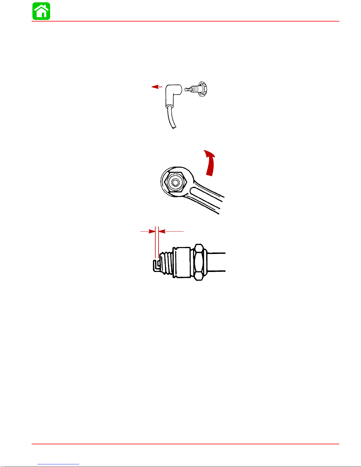
SparkPlug Inspection
Inspectsparkplugsat the recommended intervals.
1.Removethe sparkplug leadsbytwisting the rubberboots slightlyand pull off.
2.Removethesparkplugstoinspectand clean.Replacesparkplug ifelectrode isworn
orthe insulatorisrough,cracked,broken,blistered orfouled.
3.Set the sparkplug gap.See Specification ChartinGeneralInformation Section.
4.Beforereinstalling sparkplugs,clean awaydirton the sparkplug seats. Install plugs
fingertight, and tighten 1/4turn ortorque to 20 lb. ft. (27.1N·m).
BatteryInspection
Thebatteryshouldbe inspectedatperiodicintervalstoensure properengine starting ca-
pability.
IMPORTANT:Readthe safety and maintenance instructionswhichaccompany
yourbattery.
1.Turn off the engine beforeservicing the battery.
2.Add waterasnecessarytokeep the batteryfull.
3.Makesurethe batteryis secure againstmovement.
4.Batterycableterminalsshouldbeclean,tight,andcorrectlyinstalled.Positivetoposi-
tive and negativeto negative.
5.Makesurethe batteryisequipped with a nonconductiveshieldto preventaccidental
shorting ofbatteryterminals.
MAINTENANCE
Page 1B-8 90-826883R2 JUNE1998
Fuse Replacement -- ElectricStartRemote ControlModels
The electric starting circuitisprotected fromoverload byaSFE20 AMPfuse. If the fuse
isblown, the electric startermotorwill notoperate.Trytolocate and correct the cause of
the overload. If the causeisnot found, the fusemayblowagain.Replacethe fusewith
afuse of the samerating.
Replacewith a newSFE20 AMPfuse.
Lubrication Points
LubricatePoints 1 thru6withQuicksilver2-4-CMarineLubricantwith Teflon or
SpecialLubricant101.
1.Steering Friction AdjustmentShaft (TillerHandleModels) -- Lubricatefitting.
2.SwivelBracket-- Lubricatefitting.
1
2
3.TransomClampScrews-- Lubricatethreads.
MAINTENANCE
90-826883R2 JUNE1998 Page 1B-9
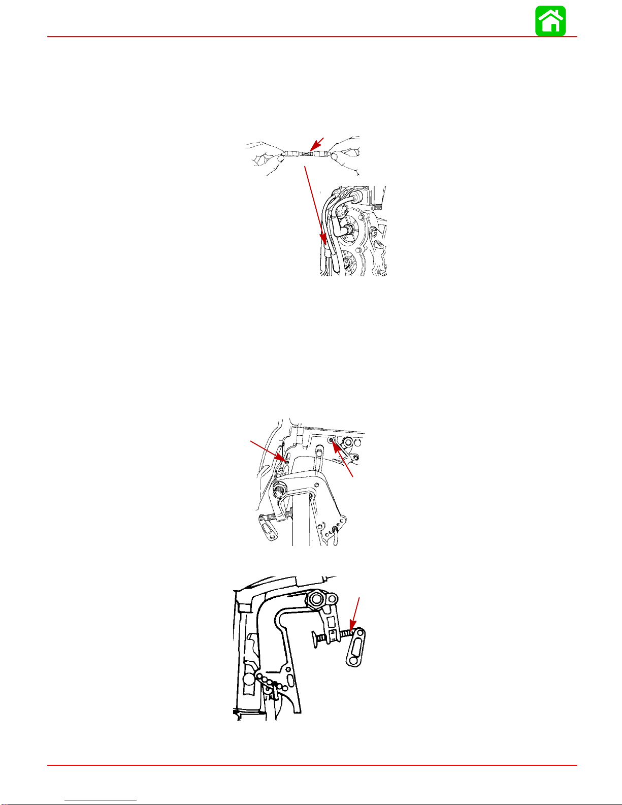
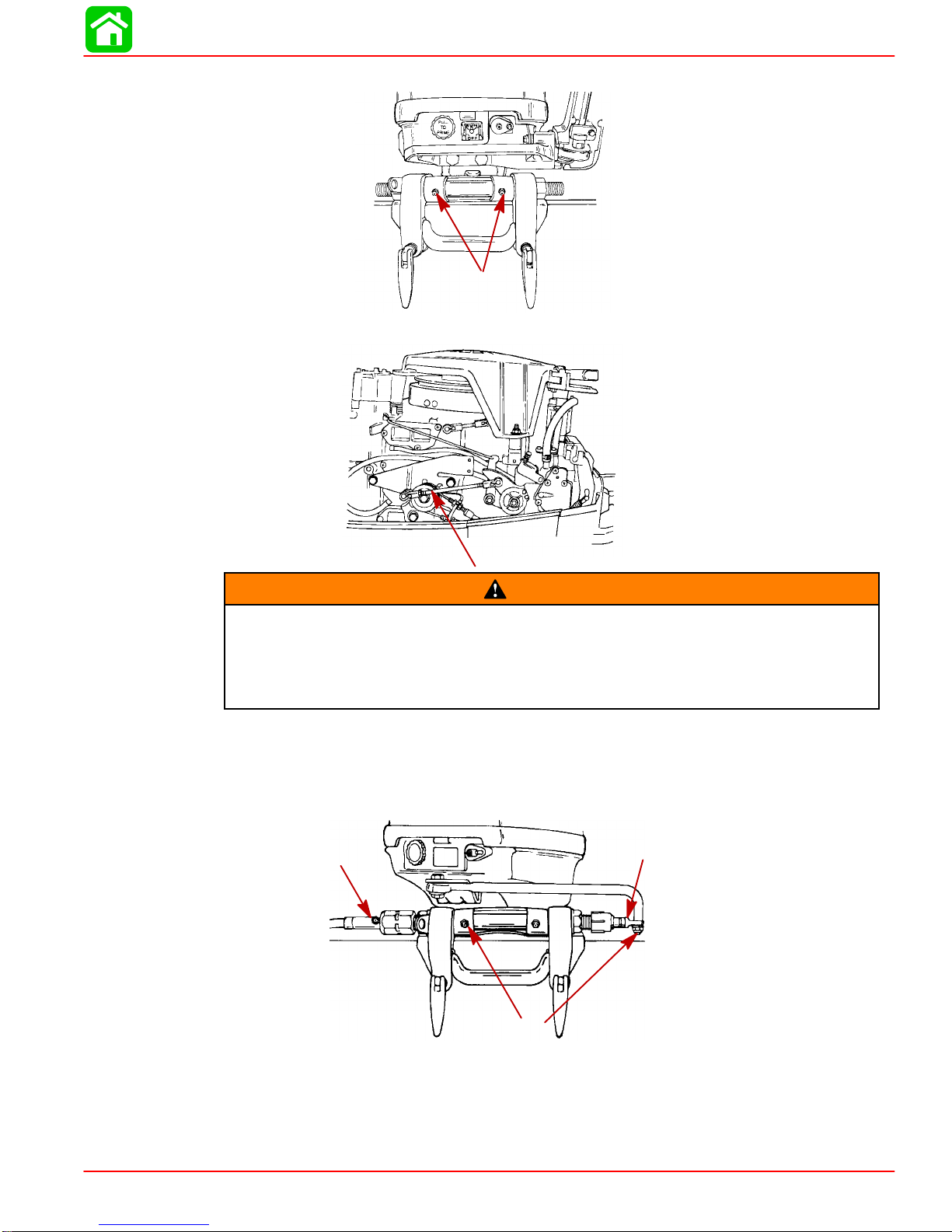
4.TiltTube -- Lubricatefittings.
5.Lubricatethe throttle and shaft cables,moving componentsand pivotlocations.
WARNING
The end of the steering cablemustbefullyretractedintotheoutboardtilt tube
before adding lubricant.Adding lubricant tosteering cablewhenfully extended
couldcause steering cableto becomehydraulicallylocked.An hydraulically
lockedsteeringcablewillcauselossofsteeringcontrol, possiblyresulting inse-
riousinjuryordeath.
6.SteeringCableGreaseFitting(IfEquipped) -- Rotatesteeringwheeltofullyretractthe
steering cable end (a)intothe outboardtilt tube.Lubricatethrough fitting (b).
Lubricatepoints 7 With LightWeightOil
7.Steering LinkRod PivotPoints-- Lubricate points.
7
6-b6-a

MAINTENANCE
Page 1B-10 90-826883R2 JUNE1998
LubricatePoint8withQuicksilverAnti-Corrosion Grease or2-4-CMarineLubri-
cantwith Teflon.
8.PropellerShaft -- RefertoPropellerReplacement for removaland installation of the
propeller.Coat the entire propellershaft withlubricant to prevent the propellerhub
fromcorroding tothe shaft.
8
GearCase Lubrication
GearCase LubricantCapacity
Gear Case Ratio Capacity
2.25:1 8.8fl.oz.(260.0ml)
Draining GearCase
When adding orchanging gearcaselubricant, visually check forthe presence ofwater
inthelubricant.Ifwaterispresent,itmayhavesettledtothebottomandwilldrainoutprior
tothelubricant,oritmaybemixedwiththelubricant,givingitamilkycoloredappearance.
Ifwaterisnoticed,havethegearcasecheckedbyyourdealer.Waterinthelubricantmay
resultinprematurebearingfailureor,infreezingtemperatures,willturntoiceanddamage
the gearcase.
Wheneveryou removethe fill/drain plug,examine the magneticend formetalparticles.
Asmall amountofmetalfilingsorfine metalparticlesindicatesnormalgearwear.An ex-
cessive amountofmetalfilingsorlargerparticles(chips)mayindicate abnormalgear
wearand should be checked byan authorized dealer.

MAINTENANCE
90-826883R2 JUNE1998 Page 1B-11
Draining GearCase
1.Place outboardin a verticaloperating position.
2.Place drain pan belowoutboard.
3.Removefill/drain plug (a)and ventplug (b)and drainlubricant.
a
b
Checking LubricantLeveland Refilling GearCase
1.Place outboardin a verticaloperating position.
2.Removeventplug fromventhole(a).
3.Placelubricant tube intothe fill hole(b)and add lubricantuntil itappearsat the vent
hole(a).
a
b
4.Stop adding lubricant. Install the ventplug and sealing washerbeforeremoving the
lubricant tube.
Other manuals for 25 MARATHON
1
Table of contents


