Mercury Security M5-2K User manual

Mercury Security © 2014 M5-2K DOC 10107-0048 REV 1.02 Page 1
www.mercury-security.com
2355 MIRA MAR AVE. LONG BEACH, CA 90815-1755, (562)986-9105 FAX (562) 986-9205
This device complies with part 15 of the FCC Rules.
Operation is subject to the following two conditions: (1) This
device may not cause harmful interference, and (2) this
device must accept any interference received, including
interference that may cause undesired operation.
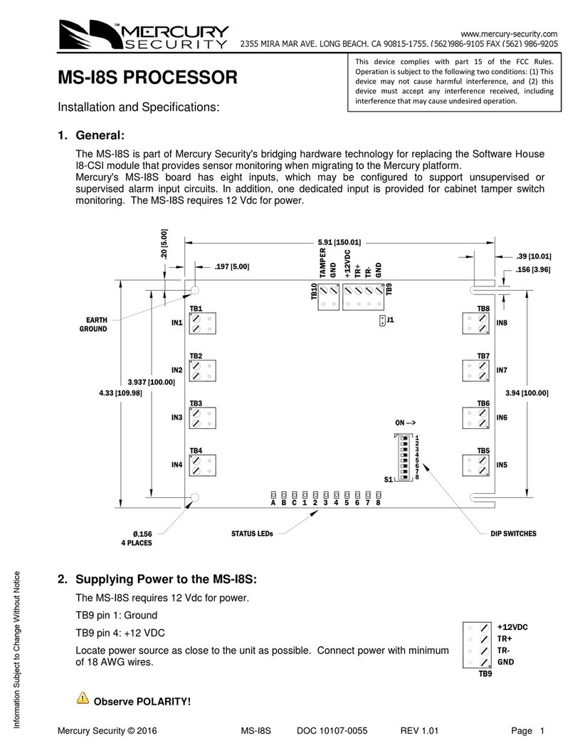
M5-2K Four Reader Interface Board
Installation and Specifications:
1. General:
Mercury’s M5-2K board for the Micro/PX-2000, Micro/PXN-2000, and MicroPXNplus® systems (M2000
enclosure) is part of Mercury Security's bridging hardware technology and provides four reader interface
ports. The M5-2K board accepts data from readers with F/2F, and supervised F/2F signaling and door
hardware. The M5-2K board provides ten inputs (un-supervised/supervised), eight Form-C control relays,
12 Vdc power supply to power readers and other devices.
The M5-IC controller board can be mounted directly on the M5-2K board or in a Micro5®enclosure.
If the M5-IC is mounted on the M5-2K board, it is powered by the M5-2K board’s internal power supply.
Power for the M5-2K board is supplied from an 18 Vac transformer. The M5-2K supports the charging of
an optional 12 Volt, 7 Ah rechargeable sealed lead-acid battery for UPS operation.
This installation manual does not contain the M5-IC controller board configuration information; see
the M5-IC Controller Board Installation and Specifications manual, DOC 10107-0040.
2. Installing the M5-2K Board:
The M5-2K and M5-IC boards replace the current M2000 enclosure’s circuit boards.
M2000 Enclosure with M5-IC and M5-2K
MOUNTING
HOLES 4X
INTERNAL GROUND STUD
2 PLACES
2
6
4
5
3
1
JP1
TB7
JP2
LO
HI
K8 K7 K6 K5 K4 K3 K2 K1
K8 K7 K6 K5 K4 K3 K2 K1
TB12 TB11 TB10 TB9
J7
TB2
TB1TB3
TB5
TB4
TB6
ON
S1
3
5
4
2
1
7
8
6
TB8
VIN
GND
TMPR
PFLT
8
GND
GND
VIN
VIN
TB1
1
J1
J7
BT1
BR/CR2325
BR/CR2330
GND
TR-
TR+
TB2 6 5 4 3
3 1 J4
2 1 4 2
3S1
1S2
ON
J6
1
1
10
10
1
1
4
4
14
14
31
8
6 16 16 16 1
1
TB2, PIN 1
INPUTS 6 - 10
TB1, PIN 1
INPUTS 1 - 5
TB5, PIN 1
READER 3
TB3, PIN1
READER 1
TB4, PIN 1
READER 2
TB6, PIN 1
READER 4
M5-2K
STATUS
LEDs
M5-IC
RESET
SWITCH
M5-IC
DIP SWITCHES
M5-IC
STATUS LEDs
M5-2K
DIP SWITCHES
REPLACE CARD
PULLER WITH
MOUNTING SCREWS,
2 EACH
12 VOLT BATTERY
CONNECT TO
CHASSIS GROUND
M5-IC
M5-2K
CONNECT TO EARTH
GROUND HERE
NO CONNECTIONS
ON M5-IC TB1
TB12, PIN 1
K7 & K8 RELAYS
TB11, PIN 1
K5 & K6 RELAYS
TB9, PIN 1
K1 & K2 RELAYS
TB10, PIN 1
K3 & K4 RELAYS
TB7, PIN 1
DOWNSTREAM COMM.
PORT 1, RS-485
JP1, PORT 1 RS-485
TERMINATION
JP2: SET TO LO
TB8, PIN1
POWER CONNECTIONS

Mercury Security © 2014 M5-2K DOC 10107-0048 REV 1.02 Page 2
M5-IC Board
The card puller must be removed from the M5-IC before mounting on the M5-2K board. Install two
mounting screws in the holes made vacate from the card puller.
S2
23
4 1
2
64
53 1 S1
ON
J4
BT1
J6
TB1
J1
BR/CR2325
BR/CR2330
TB2
RESET SWITCH
DIP SWITCHES
STATUS LEDS
TB2 - RS-485
TO DOWNSTREAM
ENCLOSUES
BATTERY:
BR/CR2325
BR/CR2330
REPLACE ANNUALLY
J6
TO MICRO/5
BACKPLANE
J7
J7
CONNECTION
TO OPTIONAL
MICRO125
STANDOFF MOUNTING
HOLES FOR OPTIONAL
MICRO125,
Ø 0.125 X 7/16 LONG
3 REQUIRED. RICHO, INC.
P/N LMSP-7-01
ON-BOARD
ETHERNET
CONNECTION
1
J4 - RS-485
TERMINATOR
GND
TR-
TR+
VIN
GND
VIN
GND
VIN
GND
TMPR
PFLT
8 13
REMOVE CARD PULLER
MOUNTING SCREWS
2 PLACES
CONNECT TO
EARTH GROUND
NO CONNECTIONS
ON M5-IC TB1

Mercury Security © 2014 M5-2K DOC 10107-0048 REV 1.02 Page 3
3. Input Power, 12 Vdc Output, Tamper Switch, and 12 Volt Battery Wiring:
Input power for the M5-2K/M5-IC assembly is provided by a wall mount 18 Vac transformer @ 2.78 A
(334 VA) connected to TB8 pins 1 and 2. The internal supply supplies power to the M5-2K/M5-IC
assembly, and charging current for a 12 volt, 7 Ah rechargeable battery. 12 Vdc output is also available
to power local devices (door strikes, annunciator devices, etc.), and downstream M5-2K enclosures. The
UPS 12 volt battery is connected to TB8 pin 7 (+) and TB8 pin 8 (-). There is a dedicated input for cabinet
tamper, connected to TB8-5 and TB8-6. Normal (safe) condition is a closed contact.
TB8-1
18 Vac ***DO NOT USE 24 Vac ***
TB8-2
18 Vac ***DO NOT USE 24 Vac ***
TB8-3
GND
TB8-4
+12 Vdc Output
TB8-5
GND (tamper switch)
TB8-6
Tamper Switch
TB8-7
12 Volt Battery, positive terminal (+)
TB8-8
12 Volt Battery, negative terminal (-)
Do not use a 24 Vac transformer to power the M5-2K/M5-IC assembly!
There must be no wires connected to TB1 of the M5-IC!
4. Ethernet Grounding:
The grounding lug on the M5-IC, identified “CGND” (located next to the Ethernet jack), must be
connected to the chassis/earth ground stud on the M200 enclosure. It is recommended to use braded
wire and make the connection as short as possible.
5. RS-485 Communication Wiring:
The M5-IC communicates to the M5-2K using 2-wire RS-485 on downstream communication port 1. This
communication port also appears on TB7 of the M5-2K. An additional 31 downstream I/O devices can be
supported on this communication port.
If the M5-IC is mounted on the M5-2K, TB2 of the M5-IC is the 2-wire RS-485 downstream
communication port 2, which can communicate to an additional 32 downstream I/O devices.
2-Wire RS-485 Communication
Port 2 (M5-IC)
2-Wire RS-485 Communication
Port 1 (M5-2K)
TB2
GND
TR-
TR+
1
3
DRAIN WIRE
SHIELD
TB7
GND
TR-
TR+
1
3
DRAIN WIRE
SHIELD

Mercury Security © 2014 M5-2K DOC 10107-0048 REV 1.02 Page 4
6. DIP Switch Usage:
Switches 1 to 5 select the device address.
Switch 6 and 7 select the communication baud rate.
Switch 8 select if encrypted communication is required.
All other configuration settings are set via host software.
SELECTION
S1
S2
S3
S4
S5
S6
S7
S8
Address 0
OFF
OFF
OFF
OFF
OFF
Address 1
ON
OFF
OFF
OFF
OFF
Address 2
OFF
ON
OFF
OFF
OFF
Address 3
ON
ON
OFF
OFF
OFF
Address 4
OFF
OFF
ON
OFF
OFF
Address 5
ON
OFF
ON
OFF
OFF
Address 6
OFF
ON
ON
OFF
OFF
Address 7
ON
ON
ON
OFF
OFF
Address 8
OFF
OFF
OFF
ON
OFF
Address 9
ON
OFF
OFF
ON
OFF
Address 10
OFF
ON
OFF
ON
OFF
Address 11
ON
ON
OFF
ON
OFF
Address 12
OFF
OFF
ON
ON
OFF
Address 13
ON
OFF
ON
ON
OFF
Address 14
OFF
ON
ON
ON
OFF
Address 15
ON
ON
ON
ON
OFF
Address 16
OFF
OFF
OFF
OFF
ON
Address 17
ON
OFF
OFF
OFF
ON
Address 18
OFF
ON
OFF
OFF
ON
Address 19
ON
ON
OFF
OFF
ON
Address 20
OFF
OFF
ON
OFF
ON
Address 21
ON
OFF
ON
OFF
ON
Address 22
OFF
ON
ON
OFF
ON
Address 23
ON
ON
ON
OFF
ON
Address 24
OFF
OFF
OFF
ON
ON
Address 25
ON
OFF
OFF
ON
ON
Address 26
OFF
ON
OFF
ON
ON
Address 27
ON
ON
OFF
ON
ON
Address 28
OFF
OFF
ON
ON
ON
Address 29
ON
OFF
ON
ON
ON
Address 30
OFF
ON
ON
ON
ON
Address 31
ON
ON
ON
ON
ON
115,200 BPS
OFF
OFF
119,600 BPS
ON
OFF
19,200 BPS
OFF
ON
38,400 BPS
ON
ON
Encrypted communication not required
OFF
Encrypted communication required
ON

Mercury Security © 2014 M5-2K DOC 10107-0048 REV 1.02 Page 5
7. Reader Wiring:
Each of the four reader ports support F/2F, and supervised F/2F type readers.
Reader cable requirements: See specification section for more details.
F/2F and supervised F/2F readers require a shielded 4-conductor cable.
F/2F or Supervised F/2F Reader
M5-2K Reader Port Terminal Block Definitions:
TB3: Reader Port 1
TB4: Reader Port 2
TB5: Reader Port 3
TB6: Reader Port 4
TB3-1
+12 Vdc
TB4-1
+12 Vdc
TB5-1
+12 Vdc
TB6-1
+12 Vdc
TB3-2
GND
TB4-2
GND
TB5-2
GND
TB6-2
GND
TB3-3
DI
TB4-3
DI
TB5-3
DI
TB6-3
DI
TB3-4
DO1
TB4-4
DO2
TB5-4
DO3
TB6-4
DO4
8. Door Position Monitor and REX Input Wiring:
The door position monitor and REX switches can be wired in two different configurations.
1. Supervised F/2F readers: door contacts and REX inputs are to be wired through the reader
2. F/2F readers: door contacts and REX inputs must be wired to the M5-2K inputs, see Section 9
Typically, the door position monitor switch uses the Normally Close (NC) contact and the REX uses the
Normally Open (NO) contact. Some supervised F/2F readers support different switch configurations
which are defined in the host and downloaded to the M5-2K.
Supervised Inputs - Wired to Supervised F/2F Reader, 4-State Supervision:
Supervised inputs for the door position monitor and REX switches are wired directly to the supervised
F/2F reader configured for 4-State Supervision. See reader’s documentation for the proper connection
terminals. Typically, the EOL resistors are two 1K ohm resistors as shown below. The EOL resistors
should be installed as close to the switch as possible.
DI
DOx
3DI
4LED
+12 Vdc
GROUND
1VO
2GND
1
F/2F Reader
4

Mercury Security © 2014 M5-2K DOC 10107-0048 REV 1.02 Page 6
Supervised F/2F Reader 4-State Input Wiring
Unsupervised Inputs - Wired to Supervised F/2F Reader, 2-State Supervision:
Unsupervised inputs for the door position monitor and REX switches are wired directly to a supervised
F/2F reader configured for 2-State Supervision. See reader’s documentation for the proper connection
terminals. EOL resistors are not required.
Supervised F/2F Reader 2-State Input Wiring
9. Input Wiring:
Typically, these inputs are used to monitor door position, request to exit, or general purpose alarm
contacts. Input circuits can be configured as unsupervised or supervised. When unsupervised, reporting
consists of only the open or closed states.
When an input circuit is configured for supervision, the M5-2K board also monitors the following abnormal
circuit conditions: open circuit, shorted circuit, grounding of either side of the circuit*, or the introduction of
a foreign voltage*. A supervised input circuit requires adding two resistors to the circuit to facilitate proper
reporting. The standard supervised circuit requires 1K Ohm, 1 % resistors and should be located as
close to the sensor as possible. Custom end of line (EOL) resistances may be configured via the host
software.
DI
DOx
+12 Vdc
TO M5-2K READER PORT
NORMALLY CLOSED CONTACT
DOOR MONITOR SWITCH
REQUEST TO EXIT SWITCH
NORMALLY OPEN CONTACT
1K, 1%
1K, 1%
1K, 1%
1K, 1%
Supervised F/2F Reader
GROUND
DI
GROUND
+12 Vdc
TO M5-2K READER PORT
Supervised F/2F Reader
NORMALLY CLOSED CONTACT
DOOR MONITOR SWITCH
REQUEST TO EXIT SWITCH
NORMALLY OPEN CONTACT
DOx

Mercury Security © 2014 M5-2K DOC 10107-0048 REV 1.02 Page 7
*Grounded and foreign voltage states are not UL 294 required and therefore not verified by UL.
The input circuit wiring configurations shown are supported, but may not be typical:
M5-2K Input Wiring –Supervised and Non-supervised
Door position monitor and REX inputs must be wired to the M5-2K when using F/2F readers. EOL
resistors are typically two 1K ohm resistors as shown below. The EOL resistors should be installed
as close to the switch as possible.
M5-2K Input Terminal Block Definitions:
TB1: Inputs 1 thru 5
TB2: Inputs 6 thru 10
TB1-1
DI 1
TB2-1
DI 6
TB1-2
DI 1 return
TB2-2
DI 6 return
TB1-3
DI 2
TB2-3
DI 7
TB1-4
DI 2 return
TB2-4
DI 7 return
TB1-5
DI 3
TB2-5
DI 8
TB1-6
DI 3 return
TB2-6
DI 8 return
TB1-7
DI 4
TB2-7
DI 9
TB1-8
DI 4 return
TB2-8
DI 9 return
TB1-9
DI 5
TB2-9
DI 10
TB1-10
DI 5 return
TB2-10
DI 10 return
10.Door Strike Wiring using an External Relay:
Instead of using the on-board relay to control the door strike, an external relay may be used. This
external relay is controlled by the reader DOx output.
If the LED in the reader is driven by the reader port DOx signal, a blocking diode must be added to the
circuit. This blocking diode should be a Schottky barrier rectifier, type 1N5817 or equivalent (20 volt @ 1
A).
Important note:
The external relay’s coil current must be restricted to 40 mA. The coil resistance of a 12 volt relay
must be 300 ohms or greater.
1K,1%
1K,1%
1K,1%
1K,1%
Standard Supervised Circuit,
Normally Open Contact
Normally Closed Contact
Standard Supervised Circuit,
Normally Closed Contact
Unsupervised Circuit,
Normally Open Contact
Unsupervised Circuit,

Mercury Security © 2014 M5-2K DOC 10107-0048 REV 1.02 Page 8
SUPPRESSION
DIODE
SELECTION:
Diode current
rating: > 1 x strike
current Diode break
down voltage: 4x
strike voltage.
For 12 Vdc or 24
Vdc strike,
diode 1N4002
(100 V / 1 A) typical
External Door Strike Relay - DC Strike
SUPPRESSION
MOV
SELECTION:
Clamp voltage >
1.5 x Vac RMS
For 24 Vac strike,
Panasonic
ERZ-C07DK470
typical
External Door Strike Relay - AC Strike
11.Door Strike Wiring using the Internal Relays:
The M2-2K board has eight Form-C contact relays for controlling door strikes or other devices. Relay
contact rating: 2 A @ 30 Vac/dc maximum.
Excessive load switching causes contact wear and premature failure. Inductive load (strike)
switching causes EMI (electromagnetic interference) which may interfere with normal operation of
other equipment. To minimize premature contact failure and to increase system reliability, a
contact protection circuit must be used. Locate the protection circuit as close to the load as
possible (12 inches [30cm] maximum recommended). The circuit's effectiveness decreases if it is
located further away.
Use sufficiently large gauge wire for the load current to avoid voltage loss.
M5-2K Relay Terminal Block Definitions:
TB9: Relays K1 & K2
TB10: Relays K3 & K4
TB11: Relays K5 & K6
TB12: Relays K7 & K8
TB9-1
K1 C
TB10-1
K3 C
TB11-1
K5 C
TB12-1
K7 C
TB9-2
K1 NC
TB10-2
K3 NC
TB11-2
K5 NC
TB12-2
K7 NC
TB9-3
K1 NO
TB10-3
K3 NO
TB11-3
K5 NO
TB12-3
K7 NO
TB9-4
K2 C
TB10-4
K4 C
TB11-4
K6 C
TB12-4
K8 C
TB9-5
K2 NC
TB10-5
K4 NC
TB11-5
K6 NC
TB12-5
K8 NC
TB9-6
K2 NO
TB10-6
K4-NO
TB11-6
K6-NO
TB12-6
K8-NO
DC STRIKE
EXTERNAL RELAY
+12Vdc 1
4
READER LED
TO READER'S GREEN LED INPUT
DI
DOx
VO
GND
14
AC STRIKE
EXTERNAL RELAY
TO READER'S GREEN LED INPUT
READER LED
+12Vdc 1
4
DI
DOx
VO
GND
14

Mercury Security © 2014 M5-2K DOC 10107-0048 REV 1.02 Page 9
SUPPRESSION
DIODE SELECTION:
Diode current rating > 1 x strike current.
Diode break down voltage: 4x strike voltage
For 12 Vdc or 24 Vdc strike, use diode
1N4002 (100 V / 1 A) typical
DC Door Strike Wiring - Internal Relay
SUPPRESSION
MOV SELECTION:
Clamp voltage > 1.5 x Vac RMS
For 24 Vac strike, Panasonic ERZ-
C07DK470 typical
AC Door Strike Wiring - Internal Relay
12.Status LEDs:
Power-up: All LEDs OFF
Initialization: After power is applied, the M5-2SRP board initializes
Initialization complete: LEDs 1 through 4 briefly sequence ON, then OFF
Run time: After the above sequence, the LEDs have the following meanings:
LED 1: Heartbeat and On-Line Status:
Off-line: 1 second cycle, 200 ms ON / 800 ms OFF
On-line: Non-encrypted communication: flash cycle of 800 ms ON / 200 ms OFF
Encrypted communication: 4 flash cycles in 700 ms ON / then 300 ms OFF
Error Indication: Waiting for firmware download: flash cycle of 100 ms ON / 100 ms OFF
LED 2: SIO Communication Port Status:
Indicates communication activity on the communication port
LED 3: Reader Port 1:
Flashes when receiving data on the reader port 1, including supervision acknowledgment
LED 4: Reader Port 2:
Flashes when receiving data on the reader port 2, including supervision acknowledgment
LED 5: Reader Port 3:
Flashes when receiving data on the reader port 3, including supervision acknowledgment
LED 6: Reader Port 4:
Flashes when receiving data on the reader port 4, including supervision acknowledgment
DC STRIKE
6
SUPPRESSION
DIODE
FUSE
TO DC POWER SOURCE
1
K1
NC
C
NO
K2
NC
C
NO
AC STRIKE
FUSE
SUPPRESSION
MOV
TO AC POWER SOURCE
6
1
K1
NC
C
NO
K2
NC
C
NO

Mercury Security © 2014 M5-2K DOC 10107-0048 REV 1.02 Page 10
13.Specifications:
The M5-2K is for use in low voltage, Class 2 Circuits only.
Primary power: 18 Vac, ± 15 %, 2.8 A maximum
12 Vdc output 10.8 to 13.2 Vdc, 550 mA maximum
UPS battery (optional) 12 volt, 7 Ah rechargeable sealed lead-acid, 1 each supported
Battery’s approximate dimensions:
L 5.94 in (151 mm)
W 2.56 in (65 mm)
H 3.74 in (96 mm)
Relay outputs: 8 outputs, Form-C, 2 A @ 30 Vac/dc, resistive
Inputs: 10 unsupervised/supervised, standard EOL: 1K/1K ohm, 1 %, ¼ watt
Reader interface:
Reader power: 10.8 to 13.2 Vdc regulated, 300 mA maximum each reader port
DOx / External relay: Open collector, 40 mA sink maximum
Reader data inputs: TTL compatible inputs
Communication: 9600, 19200, 38400, or 115200 bps, asynchronous
Cable requirements:
Alarm inputs: 1 twisted pair per input, 22 AWG shielded. 30 ohms maximum loop
resistance
Outputs: As required for the load
Reader data: Use shielded cables
12 Vdc:
20 AWG, 500 feet maximum, reader powered by M5-2K board
18 AWG, 3000 feet maximum, reader powered locally
The above specifications are based on the typical 12 volt reader
drawing 125 mA. Reader power requirements vary between different
models.
Excessive voltage drop on long cable runs may require a larger cable gauge or powering the
reader from a local power source. Refer to the power specification for the reader being installed.
Mechanical:
Dimension: W 8.375 in (212.7 mm)
L 11.375 in (289.1 mm)
H 1.04 in (26.5 mm) without M5-IC
H 1.27 in (32.26 mm) with M5-IC
Weight (w/o connectors): 12.0 oz. (340.2 g) nominal without M5-IC
17.3 oz. (491.0 g) nominal with M5-IC
Environment:
Temperature: Storage -55 to +85 °C
Operating 0 to +50 °C
Humidity: 5 to 95 % RHNC
These specifications are subject to change without notice.
Trade names used in this document may be trademarks or registered trademarks of the manufacturers or
vendors of the respective products.

Mercury Security © 2014 M5-2K DOC 10107-0048 REV 1.02 Page 11
Warranty
Mercury Security warrants the product is free from defects in material and workmanship under normal use
and service with proper maintenance for one year from the date of factory shipment. Mercury Security
assumes no responsibility for products damaged by improper handling or installation. This warranty is
limited to the repair or replacement of the defective unit.
There are no expressed warranties other than set forth herein. Mercury Security does not make, nor
intends, nor does it authorize any agent or representative to make any other warranties, or implied
warranties, and expressly excludes and disclaims all implied warranties of merchantability or fitness for a
particular purpose.
Returns must be accompanied by a Return Material Authorization (RMA) number obtained from customer
service, and prepaid postage and insurance.
Liability
The Interface should only be used to control exits from areas where an alternative method for exit is
available. This product is not intended for, nor is rated for operation in life-critical control applications.
Mercury Security is not liable under any circumstances for loss or damage caused by or partially caused
by the misapplication or malfunction of the product. Mercury Security’s liability does not extend beyond
the purchase price of the product.
Table of contents
Other Mercury Security Computer Hardware manuals
Popular Computer Hardware manuals by other brands

vPipes
vPipes Uilleann user manual

NETGEAR
NETGEAR WG511U - Double 108Mbps Wireless A+G PC Card Network guide
IEI Technology
IEI Technology HYPER-EHL Quick installation guide

M-system
M-system M8XT2 instruction manual

Pico Macom
Pico Macom CHC16U/550 Installation and operation manual
Sparklan
Sparklan WUBR-502GN user manual
CalDigit
CalDigit RAID Card Getting started
NXP Semiconductors
NXP Semiconductors AXIOM M52259DEMOCOM Hardware user's guide
Supermicro
Supermicro FatTwin F620P3-RTBN user manual
HP
HP M8201R Installation and user guide
Panasonic
Panasonic TY-FB10HMD - Monitor Terminal Expansion... Dimensions
Cervoz
Cervoz MEC-LAN-2001i user manual
