Meritor Heavy-Duty P Series User manual


Service Notes
Information contained in this publication was in effect at the time the publication was
approved for printing and is subject to change without notice or liability. Meritor Heavy
Vehicle Systems, LLC, reserves the right to revise the information presented or to
discontinue the production of parts described at any time.
Meritor Maintenance Manual MM-0440 (Issued 09-04)
About This Manual
This manual provides maintenance and service information for
Meritor heavy-duty P Series cam brakes.
Before You Begin
1. Read and understand all instructions and procedures before
you begin to service components.
2. Read and observe all Warning and Caution hazard alert
messages in this publication. They provide information that can
help prevent serious personal injury, damage to components,
or both.
3. Follow your company’s maintenance and service, installation,
and diagnostics guidelines.
4. Use special tools when required to help avoid serious personal
injury and damage to components.
Hazard Alert Messages and Torque
Symbols
WARNING
A Warning alerts you to an instruction or procedure that you
must follow exactly to avoid serious personal injury and
damage to components.
CAUTION
A Caution alerts you to an instruction or procedure that you
must follow exactly to avoid damage to components.
@This symbol alerts you to tighten fasteners to a specified torque
value.
How to Obtain Product and Service
Information
On the Web
Visit the DriveTrain Plus™ by Meritor Tech Library at meritor.com to
easily access product and service information. The Library also
offers an interactive and printable Literature Order Form.
Meritor’s Customer Service Center
Call Meritor’s Customer Service Center at 800-535-5560.
Technical Electronic Library on CD
The DriveTrain Plus™ by Meritor Technical Electronic Library on CD
contains product and service information for most Meritor and
Meritor WABCO products. $20. Specify TP-9853.
How to Obtain Tools and Supplies
Call Meritor’s Commercial Vehicle Aftermarket at 888-725-9355 to
obtain Meritor tools and supplies.

pg. pg.
Contents
iAsbestos and Non-Asbestos Fibers
1Section 1: Exploded View
2Section 2: Introduction
Description
Cam Brake Tips
3Section 3: Removal and Disassembly
Removal
Wheel Components
4BrakeShoes
Camshaft and Slack Adjuster
5Section 4: Prepare Parts for Assembly
Clean, Dry and Inspect Parts
Clean and Dry Parts
Corrosion Protection
Inspect Parts
8Section 5: Assembly and Installation
Installation
Camshaft Assemblies
9BrakeShoes
Slack Adjusters
12 Section 6: Adjustment
Adjust the Brakes
Measure Free Stroke
13 Commercial Vehicle Safety Alliance (CVSA) Guidelines
15 Section 7: Reline the Brakes
Reline the Brakes
Installing Linings with Rivets
16 Installing Linings with Bolts
Oversize Drums
17 Section 8: Maintenance
Lubrication
Brake Assembly Components
19 Slack Adjuster
Intervals
Applications
Adjust the Brakes
20 Reline the Brakes
Important Information on Linings and Primary Shoe
Locations
21 Major Overhaul
Inspection
Before You Return the Vehicle to Service
22 Section 9: Specifications
Torque Specifications

Asbestos and Non-Asbestos Fibers
i
Meritor Maintenance Manual MM-0440 (Issued 09-04)
Figure 0.1
ASBESTOS FIBERS WARNING
The followingproceduresfor servicingbrakesare recommendedto reduce exposure to
asbestosfiber dust, a cancer andlungdisease hazard. Material Safety Data Sheetsare
available from Meritor.
Hazard Summary
Becausesomebrakelinings contain asbestos, workers who servicebrakes must understandthe
potential hazards of asbestos andprecautions for reducing risks. Exposureto airborneasbestos
dust can causeserious andpossibly fatal diseases, including asbestosis (achronic lung disease)
andcancer, principally lung cancer andmesothelioma(acancer of thelining of thechest or
abdominal cavities). Somestudies show that therisk of lung cancer among persons who smoke
andwho areexposed to asbestos is much greater than therisk for non-smokers. Symptoms of
thesediseases may not becomeapparent for 15, 20 or moreyears after thefirst exposureto
asbestos.
Accordingly, workers must usecaution to avoidcreating andbreathing dust when servicing brakes.
Specific recommended work practices for reducing exposureto asbestos dust follow. Consult your
employer for moredetails.
Recommended Work Practices
1. SeparateWork Areas. Whenever feasible, servicebrakes in aseparatearea away from other
operations to reducerisks to unprotected persons. OSHA has set amaximum allowablelevel of
exposurefor asbestos of 0.1 f/cc as an 8-hour time-weighted averageand1.0 f/cc averaged over
a30-minuteperiod. Scientists disagree,however, to what extent adherenceto themaximum
allowableexposurelevels will eliminatetherisk of diseasethat can result from inhaling asbestos
dust. OSHA requires that thefollowing sign be posted at theentranceto areas whereexposures
exceed either of themaximum allowablelevels:
DANGER: ASBESTOS
CANCER AND LUNGDISEASE HAZARD
AUTHORIZED PERSONNEL ONLY
RESPIRATORSAND PROTECTIVE CLOTHING
ARE REQUIRED IN THISAREA.
2. Respiratory Protection. Wear arespirator equipped with ahigh-efficiency (HEPA) filter
approved by NIOSH or MSHA for usewith asbestos at all times when servicing brakes, beginning
with theremoval of thewheels.
3. Procedures for Servicing Brakes.
a. Enclosethebrakeassembly within anegativepressureenclosure. Theenclosureshouldbe
equipped with aHEPA vacuum andworker arm sleeves. With theenclosurein place, usethe
HEPA vacuum to loosen andvacuum residuefrom thebrakeparts.
b. As an alternativeprocedure, useacatch basin with water andabiodegradable,
non-phosphate, water-based detergent to wash thebrakedrum or rotor andother brake
parts. Thesolution shouldbe applied with low pressureto prevent dust from becoming
airborne. Allow thesolution to flow between thebrakedrum andthebrakesupport or the
brakerotor andcaliper. Thewheel hubandbrakeassembly components shouldbe thoroughly
wetted to suppress dust beforethebrakeshoes or brakepads areremoved. Wipethebrake
parts clean with acloth.
c. If an enclosed vacuum system or brakewashing equipment is not available, employers may
adopt their own written procedures for servicing brakes, provided that theexposurelevels
associated with theemployer’s procedures do not exceed thelevels associated with the
enclosed vacuum system or brakewashing equipment. Consult OSHA regulations for more
details.
d. Wear arespirator equipped with aHEPA filter approved by NIOSH or MSHA for usewith
asbestos when grinding or machining brakelinings. In addition, do such work in an area with
alocal exhaust ventilation system equipped with aHEPA filter.
e. NEVER usecompressed air by itself, dry brushing, or avacuum not equipped with aHEPA
filter when cleaning brakeparts or assemblies. NEVER usecarcinogenic solvents, flammable
solvents, or solvents that can damagebrakecomponents as wetting agents.
4. Cleaning Work Areas. Clean work areas with avacuum equipped with aHEPA filter or by wet
wiping. NEVER usecompressed air or dry sweeping to clean work areas. When you empty vacuum
cleaners andhandleused rags, wear arespirator equipped with aHEPA filter approved by NIOSH
or MSHA for usewith asbestos. When you replaceaHEPA filter, wet thefilter with afinemist of
water anddisposeof theused filter with care.
5. Worker Clean-Up. After servicing brakes, wash your hands beforeyou eat, drink or smoke.
Shower after work. Do not wear work clothes home. Useavacuum equipped with aHEPA filter to
vacuum work clothes after they areworn. Launder them separately. Do not shakeor use
compressed air to removedust from work clothes.
6. WasteDisposal. Disposeof discarded linings, used rags, cloths andHEPA filters with care,
such as in sealed plastic bags. Consult applicableEPA, stateandlocal regulations on waste
disposal.
Regulatory Guidance
References to OSHA, NIOSH, MSHA, andEPA, which areregulatory agencies in theUnited States,
aremade to provide further guidanceto employers andworkers employed within theUnited States.
Employers andworkers employed outside of theUnited States shouldconsult theregulations that
apply to them for further guidance.
NON-ASBESTOS FIBERS WARNING
The followingproceduresfor servicingbrakesare recommendedto reduce exposure to
non-asbestosfiber dust, a cancer andlungdisease hazard. Material Safety Data Sheets
are available from Meritor.
Hazard Summary
Most recently manufactured brakelinings do not contain asbestos fibers. Thesebrakelinings may
contain oneor moreof avariety of ingredients, including glass fibers, mineral wool, aramidfibers,
ceramic fibers andsilicathat can present health risks if inhaled. Scientists disagree on theextent
of therisks from exposureto thesesubstances. Nonetheless, exposureto silicadust can cause
silicosis, anon-cancerous lung disease. Silicosis gradually reduces lung capacity andefficiency
andcan result in serious breathing difficulty. Somescientists believeother types of non-asbestos
fibers, when inhaled, can causesimilar diseases of thelung. In addition, silicadust andceramic
fiber dust areknown to theStateof Californiato causelung cancer. U.S. andinternational
agencies havealso determined that dust from mineral wool, ceramic fibers andsilicaarepotential
causes of cancer.
Accordingly, workers must usecaution to avoidcreating andbreathing dust when servicing brakes.
Specific recommended work practices for reducing exposureto non-asbestos dust follow. Consult
your employer for moredetails.
Recommended Work Practices
1. SeparateWork Areas. Whenever feasible, servicebrakes in aseparatearea away from other
operations to reducerisks to unprotected persons.
2. Respiratory Protection. OSHA has set amaximum allowablelevel of exposurefor silicaof
0.1 mg/m3 as an 8-hour time-weighted average. Somemanufacturers of non-asbestos brake
linings recommendthat exposures to other ingredients foundin non-asbestos brakelinings be
kept below 1.0 f/cc as an 8-hour time-weighted average. Scientists disagree, however, to what
extent adherenceto thesemaximum allowableexposurelevels will eliminatetherisk of disease
that can result from inhaling non-asbestos dust.
Therefore, wear respiratory protection at all times during brakeservicing, beginning with the
removal of thewheels. Wear arespirator equipped with ahigh-efficiency (HEPA) filter approved by
NIOSH or MSHA, if theexposurelevels may exceed OSHA or manufacturers’recommended
maximum levels. Even when exposures areexpected to be within themaximum allowablelevels,
wearing such arespirator at all times during brakeservicing will help minimizeexposure.
3. Procedures for Servicing Brakes.
a. Enclosethebrakeassembly within anegativepressureenclosure. Theenclosureshouldbe
equipped with aHEPA vacuum andworker arm sleeves. With theenclosurein place, usethe
HEPA vacuum to loosen andvacuum residuefrom thebrakeparts.
b. As an alternativeprocedure, useacatch basin with water andabiodegradable,
non-phosphate, water-based detergent to wash thebrakedrum or rotor andother brake
parts. Thesolution shouldbe applied with low pressureto prevent dust from becoming
airborne. Allow thesolution to flow between thebrakedrum andthebrakesupport or the
brakerotor andcaliper. Thewheel hubandbrakeassembly components shouldbe thoroughly
wetted to suppress dust beforethebrakeshoes or brakepads areremoved. Wipethebrake
parts clean with acloth.
c. If an enclosed vacuum system or brakewashing equipment is not available, carefully clean
thebrakeparts in theopen air. Wet theparts with asolution applied with apump-spray bottle
that creates afinemist. Useasolution containing water, and,if available, abiodegradable,
non-phosphate, water-based detergent. Thewheel hubandbrakeassembly components
shouldbe thoroughly wetted to suppress dust beforethebrakeshoes or brakepads are
removed. Wipethebrakeparts clean with acloth.
d. Wear arespirator equipped with aHEPA filter approved by NIOSH or MSHA when grinding or
machining brakelinings. In addition, do such work in an area with alocal exhaust ventilation
system equipped with aHEPA filter.
e. NEVER usecompressed air by itself, dry brushing, or avacuum not equipped with aHEPA
filter when cleaning brakeparts or assemblies. NEVER usecarcinogenic solvents, flammable
solvents, or solvents that can damagebrakecomponents as wetting agents.
4. Cleaning Work Areas. Clean work areas with avacuum equipped with aHEPA filter or by wet
wiping. NEVER usecompressed air or dry sweeping to clean work areas. When you empty vacuum
cleaners andhandleused rags, wear arespirator equipped with aHEPA filter approved by NIOSH
or MSHA, to minimizeexposure. When you replaceaHEPA filter, wet thefilter with afinemist of
water anddisposeof theused filter with care.
5. Worker Clean-Up. After servicing brakes, wash your hands beforeyou eat, drink or smoke.
Shower after work. Do not wear work clothes home. Useavacuum equipped with aHEPA filter to
vacuum work clothes after they areworn. Launder them separately. Do not shakeor use
compressed air to removedust from work clothes.
6. WasteDisposal. Disposeof discarded linings, used rags, cloths andHEPA filters with care,
such as in sealed plastic bags. Consult applicableEPA, stateandlocal regulations on waste
disposal.
Regulatory Guidance
References to OSHA, NIOSH, MSHA, andEPA, which areregulatory agencies in theUnited States,
aremade to provide further guidanceto employers andworkers employed within theUnited States.
Employers andworkers employed outside of theUnited States shouldconsult theregulations that
apply to them for further guidance.

1 Exploded View
1
Meritor Maintenance Manual MM-0440 (Issued 09-04)
1 Exploded View
Figure 1.1
22
21
20
23
19
18
16
17
13
14
15
12
4004493a
11
10
9
6
7
8
12345
Item Description
1Camshaft and Chamber Bracket
2Bracket Capscrews
3Bracket Lock Washers
4Bracket-to-Spider Spacer
5Manual Slack Adjuster
6Cam Spacing Washer
7Cam Head Washer
8Small Spacing Washer
9Cam Needle Bearing
10 Shoe and Lining Assembly
11 Anchor Pin Lock Screw
12 Brake Spider
13 Brake Shoe Anchor Pin
14 Anchor Pin Lock
15 Anchor Pin Felt Retainer
16 Anchor Pin Felt
17 Shoe Return Spring
18 Double Head Cam
19 Clevis Pin
20 Cotter Pin
21 Chamber Stud Nut
22 Chamber Stud Washer
23 Air Chamber
Item Description
2 Introduction
2Meritor Maintenance Manual MM-0440 (Issued 09-04)
2 Introduction
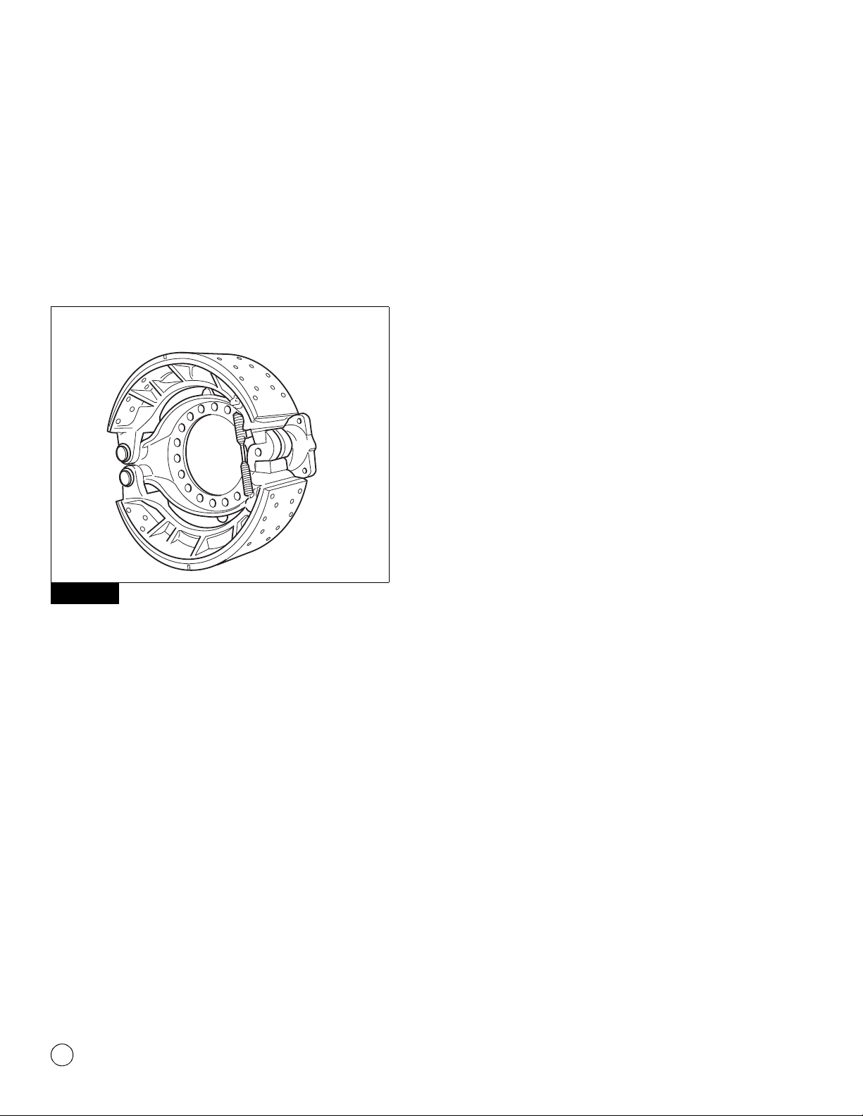
Description
Meritor P Series cam brakes are air actuated and cam operated with
two brake shoes – each mounted on a separate anchor. The brakes
are designed for heavy-duty on- or off-highway applications and
special equipment where larger shoe and drum areas are
necessary. Brake diameters of 20.25-inches and 22-inches are
available with automatic or manual adjustment. The brakes can be
assembled with auxiliary spring brakes. Figure 2.1.
Figure 2.1
Cam Brake Tips
Air Chambers
To ensure correct brake balance, all brake chambers on the same
axle must be the same size and type to help ensure a balanced
brake system for maximum lining wear and drum life.
Brake Kits
Meritor brake shoes, rollers, camshafts and shoe return springs are
designed to perform as a system. Always install original equipment
manufacturer spec-level components during maintenance or when
you upgrade from standard to long-life brakes to help ensure correct
brake performance and maximum lining life.
Cam Heads
Cam heads can look the same, but that doesn’t mean they will
perform the same in your brake system. Two cam head profiles can
appear to be identical, but very small differences in cams from
different manufacturers can be significant enough to affect the
performance of your brakes. To ensure a balanced brake system
and optimum lining and drum life, always install the correct
replacement cam.
Cam Rollers
To avoid flat spots, lubricate a cam roller directly in the web roller
pocket and not at the cam-to-roller contact area. Flat spots can
affect brake adjustment and result in premature brake wear or
reduced braking performance.
Drums
To help ensure balanced braking, even lining and drum wear, and
correct function of the automatic slack adjuster, do not install a cast
drum and a composite drum on the same axle.
A cast drum and a composite drum each absorbs and dissipates
heat differently. When drum types and weights are mixed, different
rates of heat absorption and dissipation occur that can affect the
brake system.
Hardware
When you service cam brakes, replace all the springs, anchor pins,
bushings and rollers — not just the shoe return springs — to help
ensure maximum braking performance.
Linings
Insist on the same brand of quality original equipment manufacturer
friction lining material to help ensure fewer relines and compatibility
with your present system.
Replacement Parts
Always use original equipment manufacturer quality standard parts.
Meritor brakes work as a system, and when you replace original
parts with will-fit parts, you can compromise the performance of the
entire system.
Return Springs
Replace cam brake return springs at every cam brake reline. The
return spring is critical to alignment, accurate return of the brake
away from the drum and correct automatic slack adjustment.
Trailer Cam Brakes
Long-life bushings require correct lubrication for maximum
performance and bushing life. Although you do not have to replace
spider cam bushings on trailer axles as frequently, Meritor
recommends that you lubricate the bushings at least four times
during the life of your brake lining.
Automatic Slack Adjusters
Automatic doesn’t mean maintenance-free. Correctly installed and
lubricated automatic slack adjusters help to ensure maximum brake
system performance.
Never mix automatic slack adjusters on the same axle. When you
replace automatic slack adjusters, always use replacement parts
that were originally designed for the brake system to help ensure
even brake wear, balanced braking and maximum brake
performance.
Figure 2.1
4004873b
HEAVY-DUTY “P” SERIES BRAKE
3 Removal and Disassembly
3
Meritor Maintenance Manual MM-0440 (Issued 09-04)
3 Rem oval and Disa ssembl y
Hazard Alert Messages
Read and observe all Warning and Caution hazard alert messages in
this publication. They provide information that can help prevent
serious personal injury, damage to components, or both.
WARNING
To prevent serious eye injury, always wear safe eye protection
when you perform vehicle maintenance or service.
ASBESTOS AND NON-ASBESTOS
FIBERS WARNING
Some brake linings contain asbestos fibers, a cancer and lung
disease hazard. Some brake linings contain non-asbestos
fibers, whose long-term effects to health are unknown. You
must use caution when you handle both asbestos and
non-asbestos materials.
Removal
Wheel Components
WARNING
Park the vehicle on a level surface. Block the wheels to
prevent the vehicle from moving. Support the vehicle with
safety stands. Do not work under a vehicle supported only by
jacks. Jacks can slip or fall over. Serious personal injury and
damage to components can result.
1. Park the vehicle on a level surface. Block the wheels to prevent
the vehicle from moving.
2. Use a jack to raise the vehicle so that the wheels to be serviced
are off the ground. Support the vehicle with safety stands.
WARNING
Before you service a spring chamber, carefully follow the
manufacturer’s instructions to compress and lock the spring to
completely release the brake. Verify that no air pressure
remains in the service chamber before you proceed. Sudden
release of compressed air can cause serious personal injury
and damage to components.
3. If the brake has spring chambers, carefully cage and lock the
spring, so that the spring cannot actuate during assembly.
NOTE: For complete maintenance and service information on
Meritor automatic slack adjusters, refer to Maintenance Manual 4,
Cam Brakes and Automatic Slack Adjuster. To obtain this
publication, refer to the Service Notes page on the front inside cover
of this manual.
If the slack adjuster is not a Meritor automatic slack adjuster, refer
to the manufacturer’s literature for the correct service procedures.
4. Fully release the slack adjusters so the shoes retract and the
drums will clear the linings.
CAUTION
You must disengage a pull pawl or remove a conventional pawl
before rotating the manual adjusting nut, or you will damage
the pawl teeth. A damaged pawl will not allow the slack
adjuster to automatically adjust brake clearance. Replace
damaged pawls before putting the vehicle in service.
A. Disengage the pawl.
앫If the slack adjuster has a pull pawl: Use a
screwdriver or equivalent tool to pry the pull pawl at
least 0.03125-inch (0.8 mm) to disengage the teeth.
Figure 3.1.
앫If the slack adjuster has a conventional pawl:
Remove the pawl assembly, pressure relief capscrew,
spring and pawl, from the side of the slack adjuster
housing. Figure 3.2.
Figure 3.1
Figure 3.1
CONVENTIONAL
PAWL
PULL PAWL
PRY UP
PAWL
4000331b

3 Removal and Disassembly
4Meritor Maintenance Manual MM-0440 (Issued 09-04)
Figure 3.2
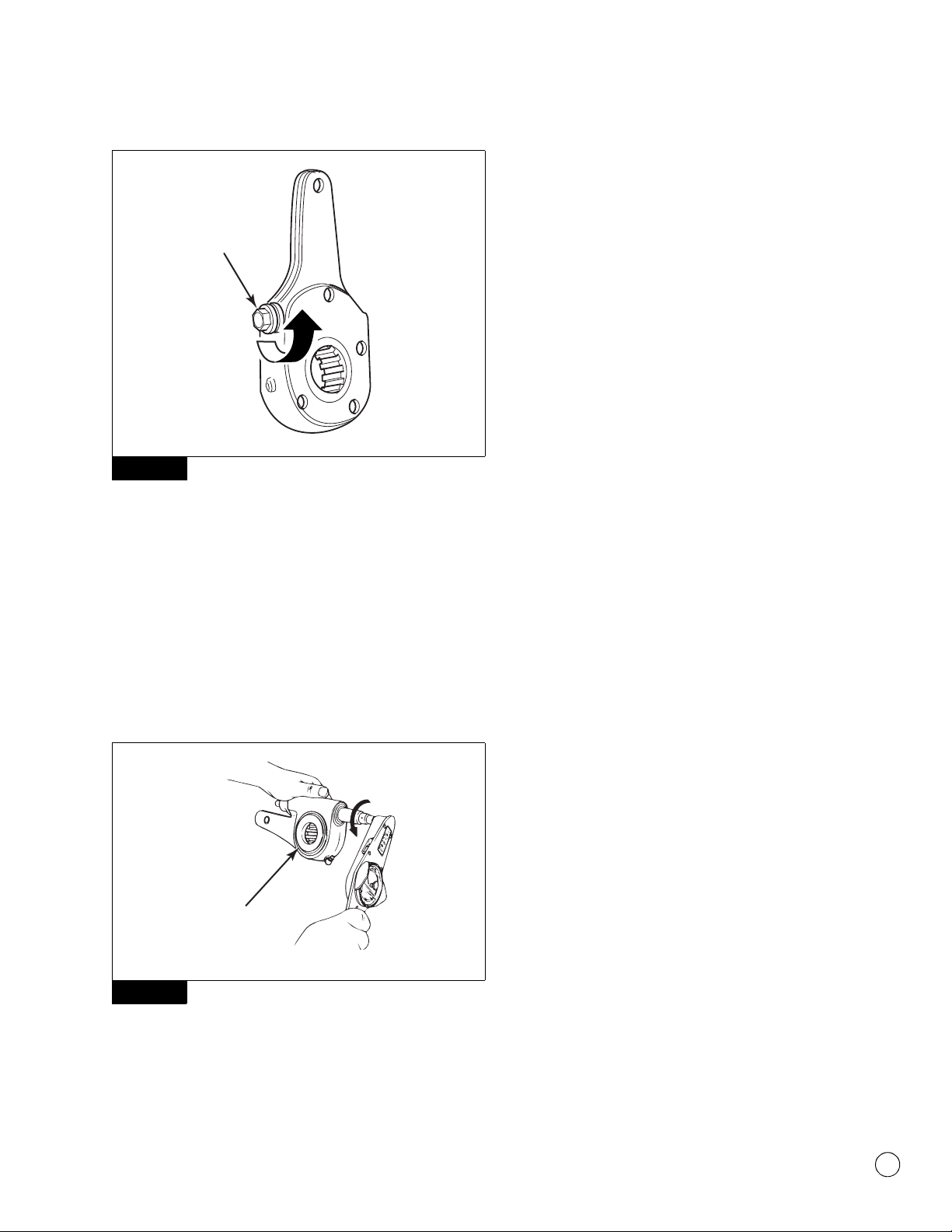
B. Use a wrench to turn the manual adjusting nut
CLOCKWISE until the brake shoes are fully retracted, and
the lining clears the drum.
C. Install the pawl into the slack adjuster housing.
5. Follow the manufacturer’s instructions to remove the wheel
and drum from the axle.
Brake Shoes
1. Remove the brake shoe return springs.
2. Remove the lock rings, retainers and felt seals from the anchor
pins.
3. Cut the lock wire and remove the anchor pin lock screws from
the brake spider. Figure 3.3.
Figure 3.3
4. Remove the anchor pins and the brake shoe assemblies.
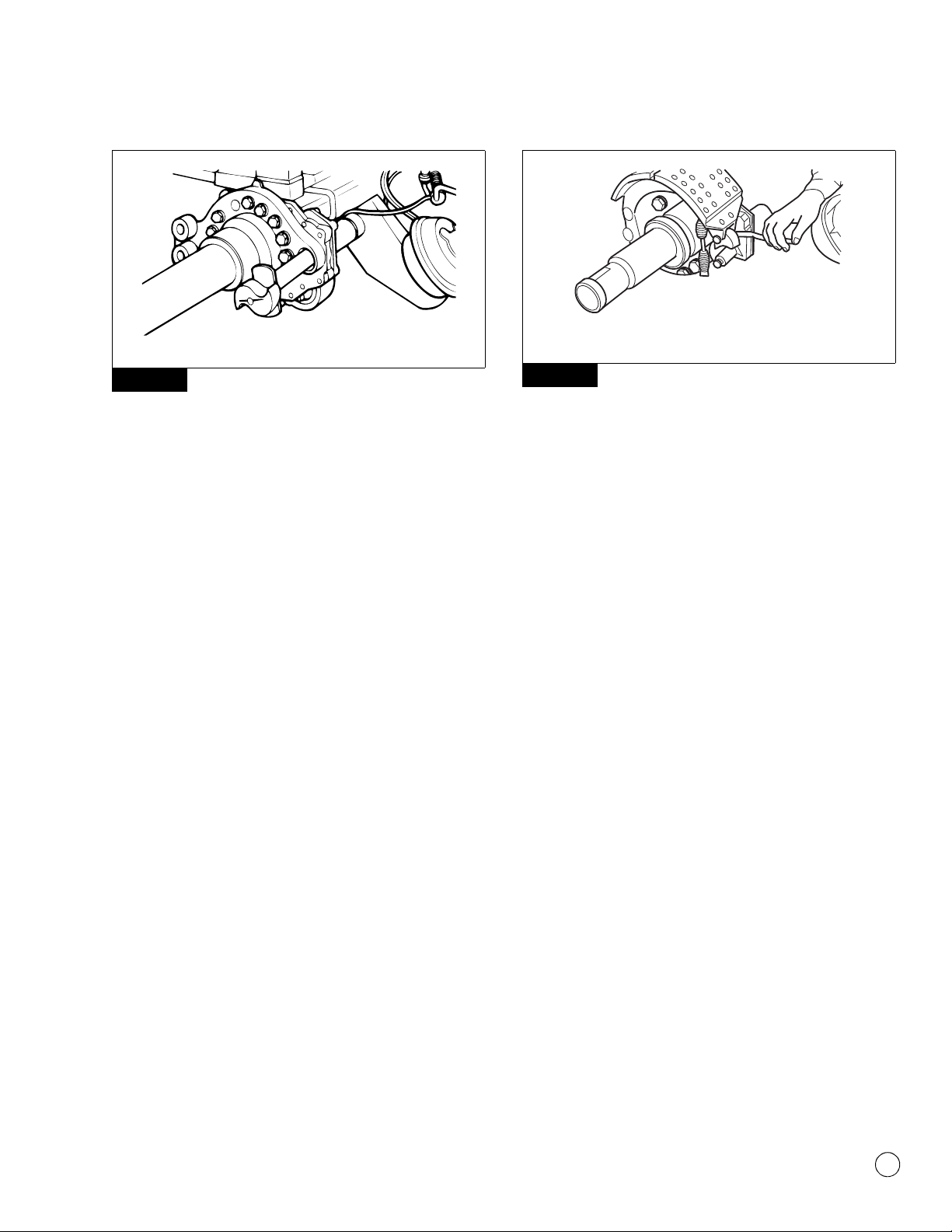
Camshaft and Slack Adjuster
1. Remove the two clevis pins from the clevis on the air chamber
push rod.
2. Remove the slack adjuster from the camshaft.
3. Check the up-and-down and side-to-side end play of the
camshaft. Figure 3.4. If end play exceeds XX.XX, replace the
needle bearings. Use a press with the correct size driver to
remove the needle bearing assemblies.
Figure 3.4
4. Remove the washers, retainers and spacers from the
camshaft.
5. Pull the camshaft from the spider and bracket.
Figure 3.2
4004494a
PAW L
ASSEMBLY
MANUAL
ADJUSTING
NUT
Figure 3.3
Figure 3.4
4004495a
LOCK
SCREWS
4000342a
0.030"
(0.76 MM)

4 Prepare Parts for Assembly
5
Meritor Maintenance Manual MM-0440 (Issued 09-04)
4 Prepare Parts for Assembly
Hazard Alert Messages
Read and observe all Warning and Caution hazard alert messages in
this publication. They provide information that can help prevent
serious personal injury, damage to components, or both.
WARNING
To prevent serious eye injury, always wear safe eye protection
when you perform vehicle maintenance or service.
ASBESTOS AND NON-ASBESTOS
FIBERS WARNING
Some brake linings contain asbestos fibers, a cancer and lung
disease hazard. Some brake linings contain non-asbestos
fibers, whose long-term effects to health are unknown. You
must use caution when you handle both asbestos and
non-asbestos materials.
Clean, Dry and Inspect Parts
Clean and Dry Parts
WARNING
Solvent cleaners can be flammable, poisonous and cause
burns. Examples of solvent cleaners are carbon tetrachloride,
and emulsion-type and petroleum-base cleaners. Read the
manufacturer’s instructions before using a solvent cleaner,
then carefully follow the instructions. Also follow the
procedures below.
앫Wear safe eye protection.
앫Wear clothing that protects your skin.
앫Work in a well-ventilated area.
앫Do not use gasoline, or solvents that contain gasoline.
Gasoline can explode.
앫You must use hot solution tanks or alkaline solutions
correctly. Read the manufacturer’s instructions before
using hot solution tanks and alkaline solutions. Then
carefully follow the instructions.
CAUTION
Do not use hot solution tanks or water and alkaline solutions to
clean ground or polished parts. Damage to parts can result.
Use soap and water to clean non-metal parts. Dry parts immediately
after cleaning with soft, clean paper or cloth, or compressed air.
Corrosion Protection
1. If you assemble parts immediately after you clean them,
lubricate parts with grease to prevent corrosion. Parts must be
clean and dry before you lubricate them. Do not apply grease
to the brake linings or the brake drums.
2. If you store parts after you clean them, apply a
corrosion-preventive material. Do not apply the material to the
brake linings or the brake drums. Store parts in a special paper
or other material that prevents corrosion.
Inspect Parts
1. Check the spider for expanded anchor pin holes and for cracks.
Replace damaged spiders and anchor pin bushings.
2. Check the camshaft bracket for broken welds, cracks and
correct alignment. Replace damaged brackets.
3. Check the anchor pins for corrosion and wear. Replace worn or
damaged anchor pins.
4. Check the brake shoes for rust, expanded rivet holes, broken
welds and correct alignment. Replace a shoe with any of the
above conditions.
5. Check the camshaft for cracks, wear and corrosion. Check the
cam head, bearing journals and splines. Replace worn or
damaged camshafts.
6. Inspect the large and small clevis pins for wear and damage.
Replace worn or damaged parts.
CAUTION
Always replace used clevis pin retainer clips with new ones
when you service an automatic slack adjuster or chamber. Do
not reuse retainer clips. Discard used clips. When you remove
a retainer clip, it can bend or “gap apart” and lose retention.
Damage to components can result.
NOTE: If you remove cotter pins from a slack adjuster during
maintenance and service procedures, Meritor recommends that you
install clevis pin retainer clips at assembly.
7. Inspect the clevis pin retainer clips or cotter pins for wear and
damage. Replace worn or damaged retainer clips and cotter
pins. Do not reuse clevis pin retainer clips. Always replace
used retainer clips with new ones. Discard used clips.
4 Prepare Parts for Assembly
6Meritor Maintenance Manual MM-0440 (Issued 09-04)
WARNING
Do not operate the vehicle with the brake drum worn or
machined beyond the discard dimension indicated on the
drum. The brake system may not operate correctly. Damage to
components and serious personal injury can result.
CAUTION
Replace the brake drum if it is out-of-round. Do not turn or
rebore a brake drum, which decreases the strength and
capacity of the drum. Damage to components can result.
8. Use the following procedure to inspect the brake drums.
A. Check the brake drums for cracks, severe heat checking,
heat spotting, scoring, pitting and distortion. Replace
drums as required. Do not turn or rebore brake drums,
which decreases the strength and heat capacity of the
drum.
B. Measure the inside diameter of the drum in several
locations with a drum caliper or internal micrometer.
Figure 4.1.
앫If the diameter exceeds the specifications
supplied by the drum manufacturer: Replace the
drum.
Figure 4.1
9. Check the dust shields for wear and damage. Repair or replace
worn or damaged parts as necessary.
Slack Adjusters
1. If the slack adjuster has a quick connect clevis, check the gap
between the clevis and the collar.
앫If the gap exceeds 0.060-inch (1.52 mm): Replace the
clevis with a one-piece threaded clevis.
2. Check the clevis pins, clips and bushing in the slack adjuster
arm for wear and damage. Replace worn or damaged parts.
Check the bushing diameter to ensure it does not exceed
0.531-inch (13.5 mm).
앫If the bushing diameter exceeds 0.531-inch (13.5 mm):
Replace the bushing.
CAUTION
You must disengage a pull pawl or remove a conventional pawl
before rotating the manual adjusting nut, or you will damage
the pawl teeth. A damaged pawl will not allow the slack
adjuster to automatically adjust brake clearance. Replace
damaged pawls before putting the vehicle in service.
NOTE: When you service an automatic slack adjuster with a
conventional pawl, replace the conventional pawl with a pull pawl.
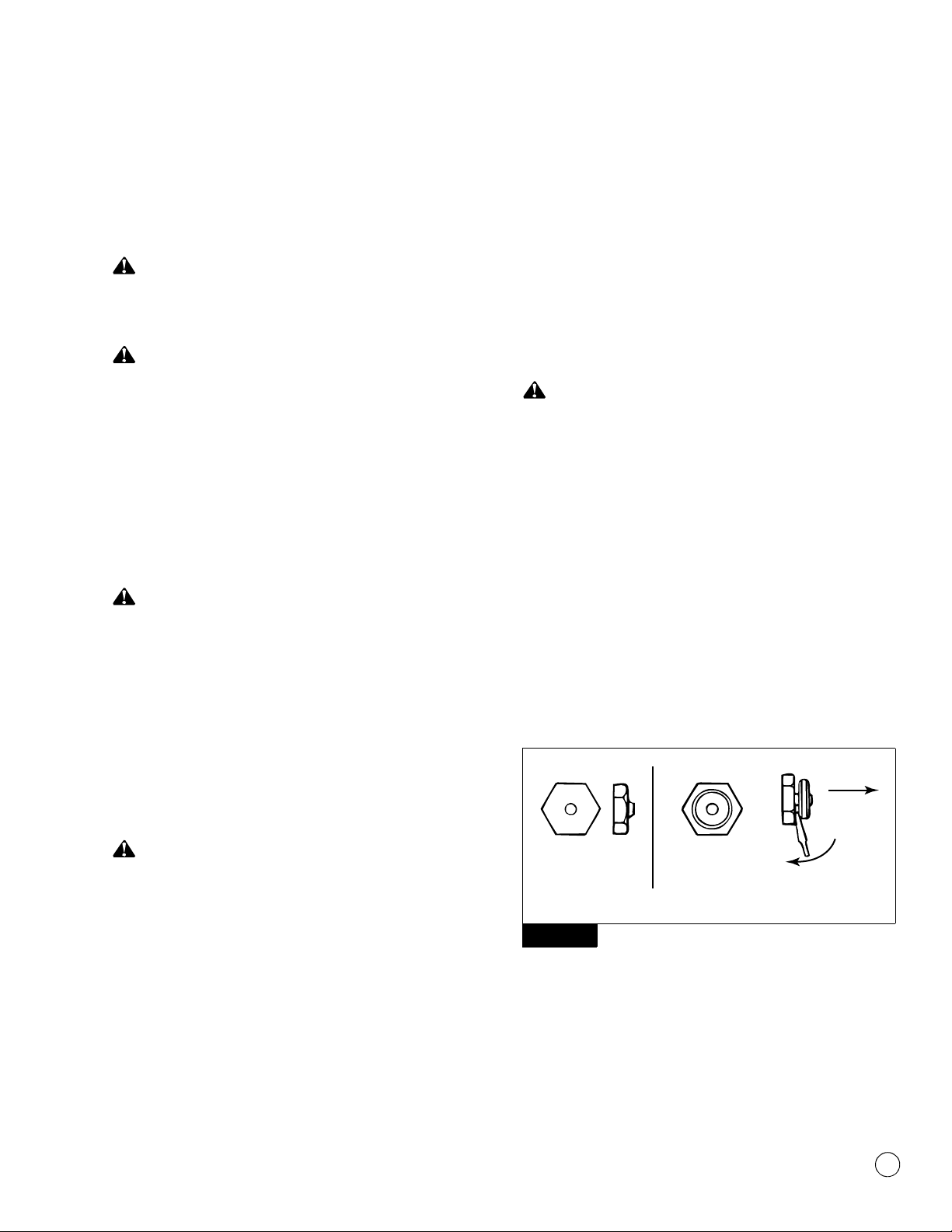
3. Disengage the pull pawl. Use a screwdriver or equivalent tool to
pry the pull pawl at least 1/32-inch (0.8 mm) to disengage the
teeth. Figure 4.2.
앫If the slack adjuster has a conventional pawl: Remove
the pawl. Figure 4.2.
Figure 4.2
CAUTION
You must turn the adjusting nut COUNTERCLOCKWISE when
you check gear torque on an automatic slack adjuster. If you
turn the adjusting nut incorrectly, you will damage the pawl
teeth. A damaged pawl will prevent the slack adjuster from
automatically adjusting the clearance between the linings and
drum. Damage to components can result.
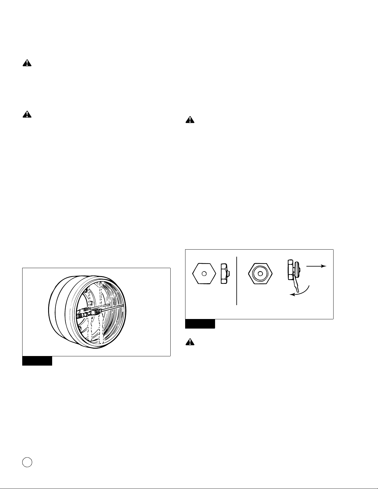
4. Check manual slack adjusters by rotating the adjustment nut of
the worm shaft to verify that the worm drive is free. Figure 4.3.
Replace the slack adjuster if the worm drive does not operate
correctly. Do NOT repair a manual slack adjuster.
Figure 4.1
4000343a
Figure 4.2
CONVENTIONAL
PAWL
PULL PAWL
PRY UP
PAWL
4000331b
4 Prepare Parts for Assembly
7
Meritor Maintenance Manual MM-0440 (Issued 09-04)
Figure 4.3
5. Use a lb-in torque wrench and turn the adjusting nut
COUNTERCLOCKWISE to rotate the gear 360 degrees, or 22
turns of the wrench, as you read the torque scale on the
wrench. The value should be less than 25 lb-in (2.83 N폷m) as
you rotate the gear. Figure 4.4.
앫If the torque value is less than 25 lb-in (2.8 N폷m) as
you rotate the gear: The slack adjuster is operating
correctly.
앫If the torque value exceeds 25 lb-in (2.8 N폷m) as you
rotate the gear: Replace the slack adjuster.
Figure 4.4
6. Re-engage the pull pawl. Remove the screwdriver or equivalent
tool. The pull pawl will re-engage automatically.
앫If the slack adjuster has a conventional pawl: Install the
pawl assembly into the housing. Tighten the capscrew to
12-17 lb-ft (16-23 N폷m). @
NOTE: If necessary, install a camshaft into the slack adjuster gear
to minimize grease flow through the gear holes.
7. Use a grease gun to apply Meritor specification O-616-A,
O-692 or O-645 lubricant to the slack adjuster grease fitting,
until grease flows from around the camshaft splines and pawl
assembly. Refer to Section 8 for more lubricant information.
Figure 4.3
Figure 4.4
4004496a
ADJUSTMENT
NUT
22 TURNS
ROTATE GEAR 360
4000344a

5 Assembly and Installation
8Meritor Maintenance Manual MM-0440 (Issued 09-04)
5 Assembly a nd Installation
Hazard Alert Messages
Read and observe all Warning and Caution hazard alert messages in
this publication. They provide information that can help prevent
serious personal injury, damage to components, or both.
WARNING
To prevent serious eye injury, always wear safe eye protection
when you perform vehicle maintenance or service.
ASBESTOS AND NON-ASBESTOS
FIBERS WARNING
Some brake linings contain asbestos fibers, a cancer and lung
disease hazard. Some brake linings contain non-asbestos
fibers, whose long-term effects to health are unknown. You
must use caution when you handle both asbestos and
non-asbestos materials.
Installation
Camshaft Assemblies
1. Tighten all the spider bolts to the specified torque. Figure 5.1.
Figure 5.1
2. Install new camshaft seals into the spider and camshaft
bracket with a seal driver. Figure 5.2. Install both seals with
their lips toward the slack adjuster. Figure 5.3.
Figure 5.2
Figure 5.3
3. If necessary, install new cage and needle bearing assemblies.
4. If the camshaft bracket was removed, install the gasket and
bracket to the spider. Tighten the capscrews to the correct
torque as specified in Section 9.
5. Install the cam head thrust washer onto the camshaft. Apply
Meritor specification O-617-A or O-617-B grease to the
camshaft needle bearings and journals.
6. Install the camshaft through the spider and bracket so that the
camshaft turns freely by hand. Figure 5.4.
Figure 5.1
4004497a
T
TORQUE
BOLT
SIZE
7/16"-20
1/2"-20
9/16"-18
5/8"-18
60-75 LB-FT
85-115 LB-FT
130-165 LB-FT
180-230 LB-FT
81-102 N·m
115-156 N·m
176-224 N·m
244-312 N·m
Figure 5.2
Figure 5.3
4000346a
SPIDER
CAMSHAFT
BRACKET
SEAL
LIP
SEAL
LIP
4000347a
5 Assembly and Installation
9
Meritor Maintenance Manual MM-0440 (Issued 09-04)
Figure 5.4
Brake Shoes
NOTE: Meritor recommends that you replace the springs, rollers
and anchor pins at each reline.
When the brake is disassembled, or when necessary, lubricate the
anchor pins and rollers where these parts touch the brake shoes.
Do not allow grease to contact the area of the camshaft roller that
touches the camshaft head.
1. Lubricate the camshaft roller pin and anchor pin with Meritor
specification O-617-A or O-617-B grease.
2. Install the brake shoes onto the spider with the anchor pins.
Verify that the flat sides of the anchor pins are aligned with the
lock screw holes in the spider.
3. Install the anchor pin felt seals, retainers and lock rings.
4. Install the anchor pin lock screws and tighten to 10-15 lb-ft
(13.56-20.34 N폷m). Install the lock wire for the lock screws.
@
5. Install new shoe return springs.
Slack Adjusters
1. Apply Meritor specification O-637 or other rust preventive
grease to the camshaft splines.
2. Install the slack adjuster spacer washer on the splined end of
the camshaft followed by the slack adjuster.
3. Add spacer washers to limit the slack adjuster end play to
0.060-inch (1.5 mm) maximum. Figure 5.5.
Figure 5.5
4. Install a new camshaft lock ring.
5. Connect the slack adjuster to the air chamber push rod.
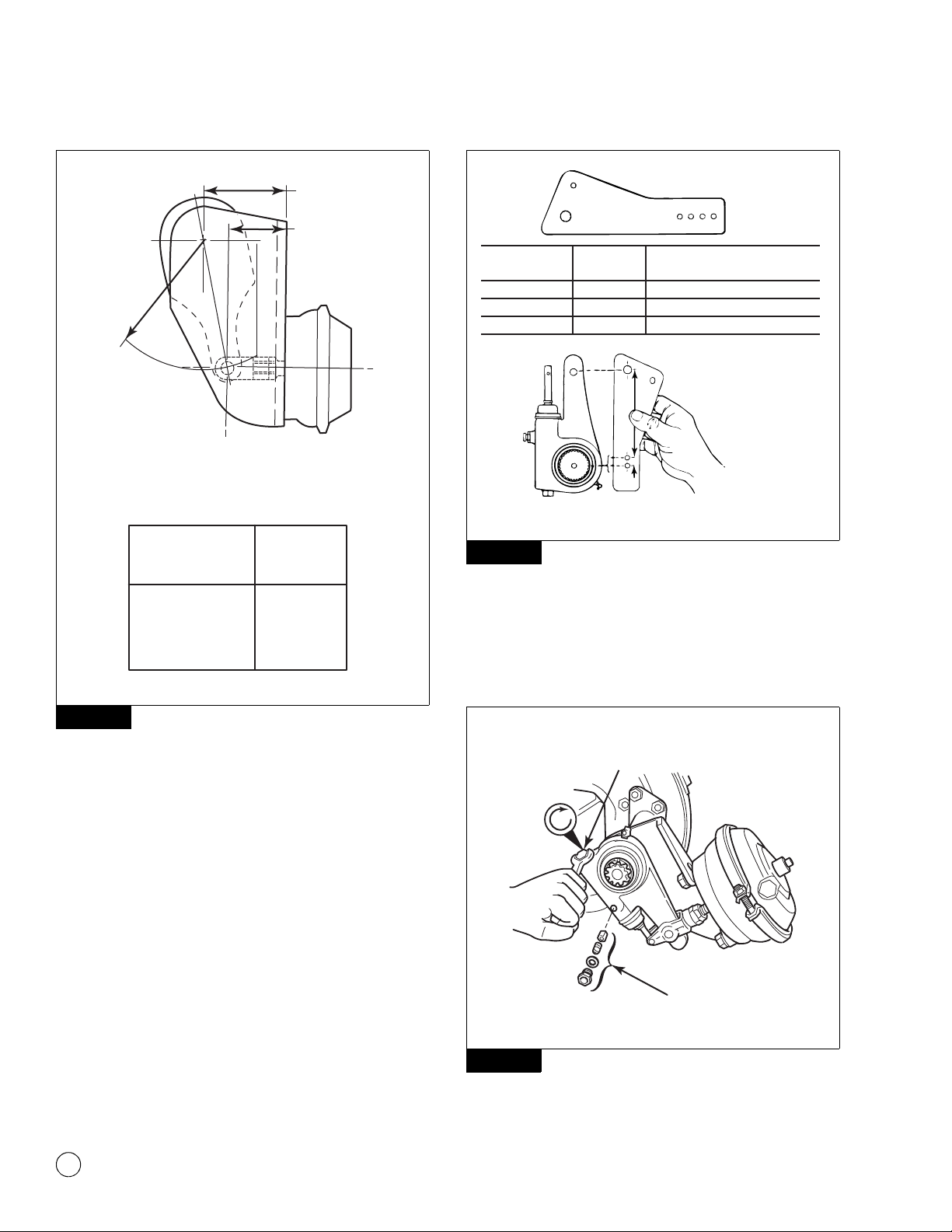
Manual Slack Adjusters
1. If the clevis was not replaced, install new clevis pins.
2. Install and adjust the slack adjuster to match the Brake Slack
Adjuster Position (BSAP). Figure 5.6.
Figure 5.4
4000348a
Figure 5.5
4004499a
Check end play.
5 Assembly and Installation
10 Meritor Maintenance Manual MM-0440 (Issued 09-04)
Figure 5.6
Automatic Slack Adjusters
1. If you install the same slack adjuster that was removed, install
the clevis on the push rod in the position you marked when you
removed the clevis. Check the position of the clevis with the
Installation template. Figure 5.7.
앫If you are installing a new slack adjuster: Verify it is the
same length as the one you are replacing. Install the clevis
on the push rod. Check the position of the clevis with the
Installation template. Figure 5.7.
Figure 5.7
2. Remove the pawl assembly and align the slack adjuster arm
with the clevis. Turn the manual adjusting nut to the left until
the clevis pin hole in the slack adjuster arm is aligned with the
large hole in the clevis. Assemble with the large clevis pin and
fasten with a cotter pin. Figure 5.8 and Figure 5.9.
Figure 5.8
Figure 5.6
4004498a
3.750 AND 3.812
BRACKET
OFFSET
BSAP ± 0.062
SLACK
LENGTH
CORRECT POSITION OF MANUAL SLACK
ADJUSTER 3.750" AND 3.812" OFFSETS ONLY
(FOR OTHER BRACKET OFFSETS, REFERTO
THE VEHICLE MANUFACTURER’S
SPECIFICATIONS)
5.00
5.50
6.00
6.50
5.00
5.50
6.00
6.50
2.84
2.75
2.67
2.59
SLACK
ADJUSTMENT
SIZE
± 0.062
BSAP
Figure 5.7
Figure 5.8
Color of
Template
Part
Number Applications
Dark brown TP-4786 Truck or tractor drum brake
Tan TP-4787 Trailer drum brake
White TP-4781 Coach drum brake
Measure the slack
adjuster
arm length.
CAMSHAFT CENTER
4000369b
4004500a
PAW L
ASSEMBLY
MANUAL
ADJUSTING
NUT

5 Assembly and Installation
11
Meritor Maintenance Manual MM-0440 (Issued 09-04)
Figure 5.9
3. Pull on the actuator rod until the hole in the top of the rod is
aligned with the small hole in the clevis. Install the small clevis
pin and fasten with a cotter pin.
4. Install the pawl assembly.
5. Apply the brakes and permit the push rods to extend fully.
There must be clearance between the slack adjuster and all
chassis components.
NOTE: Refer to Maintenance Manual 4, Cam Brakes and Automatic
Slack Adjuster, for complete installation instructions.
6. Release the brakes and verify that the manual adjusting nut
rotates to the left as the push rods fully retract.
Figure 5.9
CLEVIS LARGE CLEVIS PIN
AND
RETAINER CLIP
ACTUATOR
ROD
SMALL CLEVIS PIN
AND RETAINER CLIP
LARGE CLEVIS PIN
RETAINER CLIP
P/N 2257-D-1174
SMALL CLEVIS PIN
RETAINER CLIP
P/N 2257-C-1173
The clevis pin retainer
clips must be fully
installed and positioned
around the SIDE of the
clevis pin.
4001487a

6 Adjustment
12 Meritor Maintenance Manual MM-0440 (Issued 09-04)
6 Adjustment
Hazard Alert Messages
Read and observe all Warning and Caution hazard alert messages in
this publication. They provide information that can help prevent
serious personal injury, damage to components, or both.
WARNING
To prevent serious eye injury, always wear safe eye protection
when you perform vehicle maintenance or service.
Before you service a spring chamber, carefully follow the
manufacturer’s instructions to compress and lock the spring to
completely release the brake. Verify that no air pressure
remains in the service chamber before you proceed. Sudden
release of compressed air can cause serious personal injury
and damage to components.
ASBESTOS AND NON-ASBESTOS
FIBERS WARNING
Some brake linings contain asbestos fibers, a cancer and lung
disease hazard. Some brake linings contain non-asbestos
fibers, whose long-term effects to health are unknown. You
must use caution when you handle both asbestos and
non-asbestos materials.
Adjust the Brakes
Measure Free Stroke
When you perform preventive maintenance procedures on an
in-service brake, check both the free stroke and adjusted chamber
stroke. Refer to the procedures in this section.
Free stroke sets the clearance between the linings and drum. The
in-service free stroke may be slightly longer than 0.5-0.625-inch
(12.7-15.9 mm) specified in this procedure. This is acceptable if the
adjusted chamber stroke is within the limits shown in Table A and
Table B.
CAUTION
You must disengage a pull pawl or remove a conventional pawl
before rotating the manual adjusting nut, or you will damage
the pawl teeth. A damaged pawl will not allow the slack
adjuster to automatically adjust brake clearance. Replace
damaged pawls before putting the vehicle in service.
1. Disengage a pull pawl. Use a screwdriver or equivalent tool to
pry the pull pawl at least 1/32-inch (0.8 mm) to disengage the
teeth.
앫If the slack adjuster has a conventional pawl: Remove
the pawl.
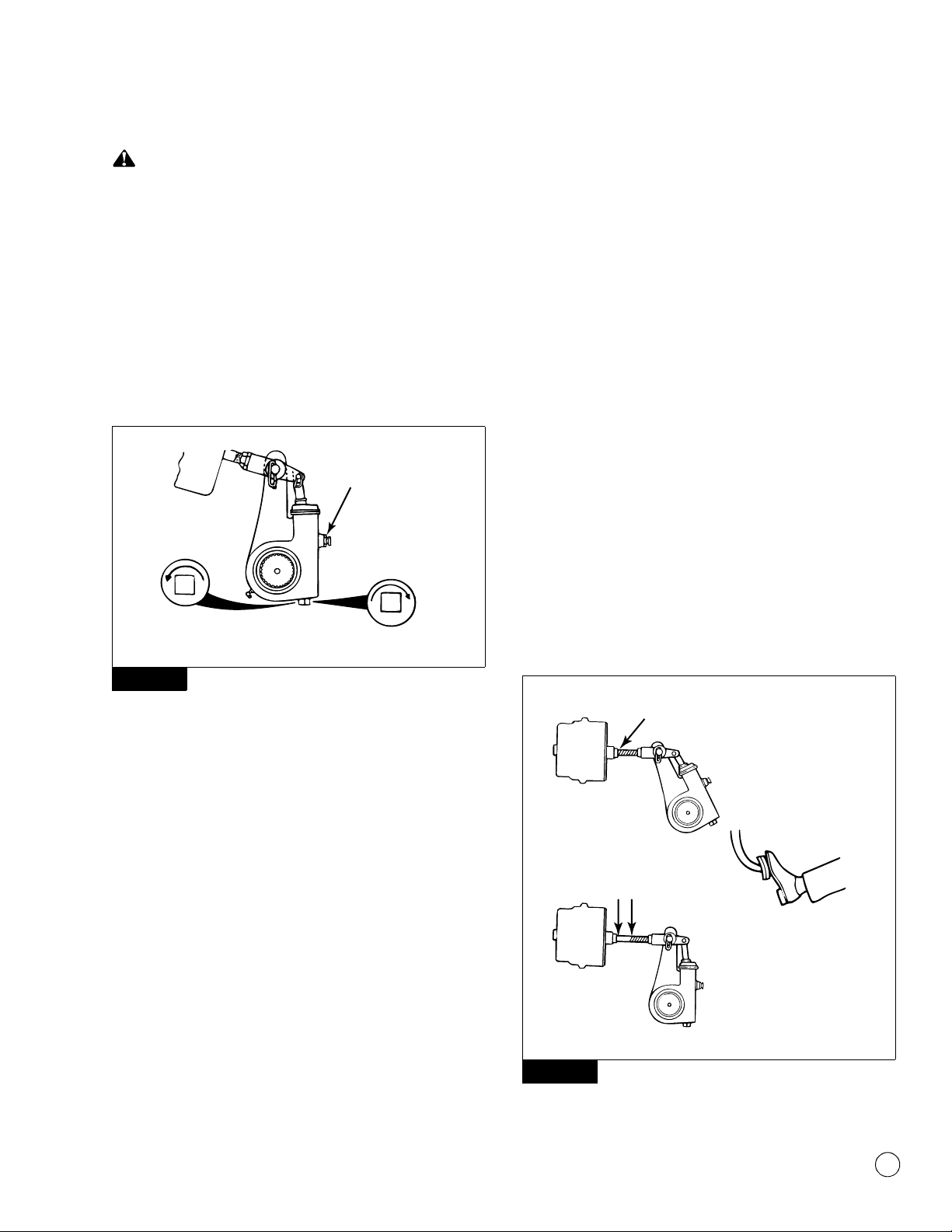
2. Use a wrench to turn the adjusting nut COUNTERCLOCKWISE
until the brake shoes contact the drum. Figure 6.1. Then back
off the adjusting nut 1/2 turn in the opposite direction.
Figure 6.1
3. Measure the distance from the center of the large clevis pin to
the bottom of the air chamber while the brake is released. The
measurement you obtain is X in Figure 6.2.
Figure 6.2
4. Use a pry bar to move the slack adjuster and position the
linings against the drum, brakes applied. Measure the same
distance again while the brakes are applied. The measurement
you obtain is Y in Figure 6.2.
Figure 6.1
Figure 6.2
Disengage pawl.
4000371e
MEASURE FREE STROKE
“Y”
“X”
FREE STROKE = Y MINUS X
Drum brake free stroke must be
0.5-0.625" (12.7-15.9 mm).
Disc brake free stroke must be
0.75-0.875" (19.1-22.2 mm).
4000372a
6 Adjustment
13
Meritor Maintenance Manual MM-0440 (Issued 09-04)
CAUTION
Do not set free stroke shorter than 0.5-0.625-inch
(12.7-15.9 mm) for drum brakes. If the measurement is too
short, linings can drag. Damage to components can result.
5. Subtract X from Y to obtain the in-service free stroke. The
measurement must be 0.5-0.625-inch (12.7-15.9 mm) for
drum brakes. Figure 6.2.
앫If the free stroke measurement is not within
specification: Turn the adjusting nut to adjust free stroke.
Figure 6.3. Follow the steps above to check free stroke
again, until the measurement is within specification.
Figure 6.3
6. Re-engage the pull pawl by removing the screwdriver or
equivalent tool. The pull pawl will re-engage automatically.
앫If the slack adjuster has a conventional pawl: Install the
pawl assembly into the housing. Tighten the capscrew to
12-17 lb-ft (16-23 N폷m). @
7. If the brakes have spring chambers, carefully release the
springs. Test the vehicle before you return it to service.
Commercial Vehicle Safety Alliance (CVSA)
Guidelines
Measure Push Rod Travel or Adjusted Chamber
Stroke
Use the following procedure to check in-service push rod travel or
adjusted chamber stroke on truck and tractor brakes.
NOTE: Hold the ruler parallel to the push rod and measure as
carefully as possible. A measurement error can affect CVSA
re-adjustment limits. CVSA states that “any brake 1/4-inch or more
past the re-adjustment limit, or any two brakes less than 1/4-inch
beyond the re-adjustment limit, will be cause for rejection.”
1. The engine must be OFF. If the brake has a spring chamber,
follow the manufacturer’s instructions to release the spring.
Verify that no air pressure remains in the service section of the
chamber.
2. Verify that pressure is 100 psi (689 kPa) in the air tanks.
Determine the size and type of brake chambers on the vehicle.
3. With the brakes released, mark the push rod where it exits the
chamber. Measure and record the distance. Have another
person apply and hold the brakes on full application.
Figure 6.4.
Figure 6.4
Figure 6.3
SHORTEN
STROKE
Disengage
pull pawl
or remove
conventional
pawl.
LENGTHEN
STROKE
4000373a
Figure 6.4
• Spring brakes
released
• Service brakes
not applied
• Spring brakes
released
• Service brakes
applied
90-100 psi (620-690 kPa)
in air tank — engine OFF
Mark push rod here
to measure stroke.
STROKE
4000374b
Step 2
Step 1
Step 3

6 Adjustment
14 Meritor Maintenance Manual MM-0440 (Issued 09-04)
4. Measure the push rod travel or adjusted chamber stroke from
where the push rod exits the brake chamber to your mark on
the push rod. Measure and record the distance. Figure 6.4.
5. Subtract the measurement you recorded in Step 3 from the
measurement you recorded in Step 4. The difference is the
push rod travel or adjusted chamber stroke.
6. Refer to Table A or Table B to verify that the stroke length is
correct for the size and type of air chambers on the vehicle.
앫If push rod travel or adjusted chamber stroke is greater
than the maximum stroke shown in Table A or Table B:
Inspect the slack adjuster and replace it, if necessary.
Table A: Standard Stroke Clamp-Type Brake Chamber Data
Table B: Long Stroke Clamp-Type Brake Chamber Data
Alternate Method to Measure Push Rod Travel or
Adjusted Chamber Stroke
Use the CVSA procedure, except in Step 3 and Step 4, measure the
distance from the bottom of the air chamber to the center of the
large clevis pin on each of the brakes.
CVSA North American Out-of-Service Criteria
Reference Tables
Information contained in Table A and Table B is for reference only.
Consult the CVSA’s Out-of-Service Criteria Handbook for North
American Standards, Appendix A. Visit their website at
http://64.35.82.7/ to obtain the handbook.
Type
Outside Diameter
(inches)
Brake
Adjustment Limit
(inches)
6 4-1/2 1-1/4
9 5-1/4 1-3/8
12 5-4/16 1-3/8
16 6-3/8 1-3/4
20 6-25/32 1-3/4
24 7-7/32 1-3/4
30 8-3/32 2
36 9 2-1/4
Type
Outside Diameter
(inches)
Brake
Adjustment Limit
(inches)
16 6-3/8 2.0
20 6-25/32 2.0
24 7-7/32 2.0
24* 7-7/32 2.5
30 8-3/32 2.5
*For 3" maximum stroke type 24 chambers.

7 Reline the Brakes
15
Meritor Maintenance Manual MM-0440 (Issued 09-04)
7 Reline the Brakes
Hazard Alert Messages
Read and observe all Warning and Caution hazard alert messages in
this publication. They provide information that can help prevent
serious personal injury, damage to components, or both.
WARNING
To prevent serious eye injury, always wear safe eye protection
when you perform vehicle maintenance or service.
ASBESTOS AND NON-ASBESTOS
FIBERS WARNING
Some brake linings contain asbestos fibers, a cancer and lung
disease hazard. Some brake linings contain non-asbestos
fibers, whose long-term effects to health are unknown. You
must use caution when you handle both asbestos and
non-asbestos materials.
Reline the Brakes
CAUTION
Reline the brakes when the lining thickness is 0.25-inch
(6.3 mm) at the thinnest point. The rivets or bolts must not
touch the drum. Damage to components will result.
Use the lining material specified by the vehicle manufacturer. This
will help to ensure that the brakes perform correctly and meet
Department of Transportation (DOT) performance regulations.
Always reline both wheels of a single axle and all four wheels of a
tandem axle at the same time. Always install the same linings and
drums on both wheels of a single axle and all four wheels of a
tandem axle. It is not necessary that the front and rear axles have
the same linings and drums.
NOTE: The primary linings must be installed onto the primary shoe.
The first shoe past the cam in the direction of wheel rotation is the
primary shoe. Figure 7.1. The primary shoe can be either at the top
or the bottom position, depending on the location of the cam. If the
cam is behind the axle, the top shoe is the primary shoe. If the cam
is in front of the axle, the bottom shoe is the primary shoe.
Figure 7.1
Installing Linings with Rivets
1. Check to ensure that the lining and shoe contact faces are
clean.
2. Align the rivet holes in the lining with the rivet holes in the
shoe.
NOTE: Verify that the rivets are the correct body diameter, head size
and shape, length and material.
3. Install the rivets into the rivet holes following the correct
sequence. Figure 7.2.
Figure 7.1
WHEEL ROTATION WHEEL ROTATION
RIGHT WHEEL ROTATION
CAM IN FRONT OF AXLECAM BEHIND AXLE
LEFT WHEEL ROTATION
WHEEL ROTATION
WHEEL ROTATION
CAM BEHIND AXLECAM IN FRONT OF AXLE
4000375a

7 Reline the Brakes
16 Meritor Maintenance Manual MM-0440 (Issued 09-04)
Figure 7.2
A gap of 0.10-inch (0.25 mm) maximum is acceptable
between the shoe and linings along the side and ends of the
assembly, except between the double web. A 0.025-inch
(0.64 mm) gap is acceptable between the webs. Figure 7.3.
Figure 7.3
Installing Linings with Bolts
NOTE: The same procedures must be followed with bolted linings
as with riveted linings. New lock washers must be used during
installation.
1. Check to ensure that the lining and shoe contact faces are
clean.
2. Align the bolt holes in the lining with the holes in the shoe.
NOTE: Verify that the bolts are the correct body diameter, head size
and shape, length and material.
3. Install the bolts and lock washers into the bolt holes following
the correct sequence. Figure 7.2.
앫Tighten 3/8-inch diameter brass bolts to 220-280 lb-in or
18-23 lb-ft (24.8-31.6 N폷m). @
앫Tighten 1/4-inch diameter brass bolts to 80-100 lb-in or
7-8 lb-ft (9-11.3 N폷m). @
Oversize Drums
CAUTION
Do not operate the vehicle with the brake drum worn or
machined beyond the discard dimension stamped on the
drum. The brake system may not operate correctly if the
drums are worn or machined beyond the discard dimension
and cause serious personal injury or damage.
To compensate for the worn or refaced drums, X (1/16-inch
oversize) and XX (1/8-inch oversize) brake linings are supplied by
the lining manufacturers.
Figure 7.2
Figure 7.3
4004502a
8
9
12
11
9
10
12
8
5
4
1
2
36
7
3
2
1
4
5
6
7
11
10
4004502a
8
9
12
11
9
10
12
8
5
4
1
2
36
7
3
2
1
4
5
6
7
11
10
Table of contents
Other Meritor Automobile Accessories manuals

Popular Automobile Accessories manuals by other brands


Prorack
Prorack K164 Fitting instructions

Cruz
Cruz 941-401 Assembly instructions

Pilot Communications
Pilot Communications EV Plus+ Quick installation guide

TOP VEHICLE TECH
TOP VEHICLE TECH GR4FORD5 installation manual

Whispbar
Whispbar K708W Fitting instructions

Arkon
Arkon SLIM-GRIP SM5-FO7309G3 user manual