Meritor RideSentry MPA Series User manual
Maintenance Manual 14R
RideSentry™ MPA Series Sliding Tandem
Trailer Air Suspension System
Revised 12-18

Service Notes
Information contained in this publication was in effect at the time the publication was
approved for printing and is subject to change without notice or liability. Meritor Heavy
Vehicle Systems, LLC, reserves the right to revise the information presented or to
discontinue the production of parts described at any time.
Meritor Maintenance Manual 14R (Revised 12-18)
About This Manual
This manual provides the correct lubrication, service and installation
procedures for the Meritor RideSentry™ MPA Series sliding tandem
trailer air suspension system.
Before You Begin
1. Read and understand all instructions and procedures before
you begin to service components.
2. Read and observe all Warning and Caution hazard alert
messages in this publication. They provide information that can
help prevent serious personal injury, damage to components,
or both.
3. Follow your company’s maintenance and service, installation,
and diagnostics guidelines.
4. Use special tools when required to help avoid serious personal
injury and damage to components.
Hazard Alert Messages and Torque
Symbols
WARNING
A Warning alerts you to an instruction or procedure that you
must follow exactly to avoid serious personal injury and
damage to components.
CAUTION
A Caution alerts you to an instruction or procedure that you
must follow exactly to avoid damage to components.
@This symbol alerts you to tighten fasteners to a specified torque
value.
How to Obtain Additional Maintenance,
Service and Product Information
Visit Literature on Demand at meritor.com to access and order
additional information.
Contact the Meritor OnTrac™ Customer Call Center at
866-668-7221 (United States and Canada); 001-800-889-1834
(Mexico); or email OnTrac@meritor.com.
If Tools and Supplies are Specified in
This Manual
Contact Meritor’s Commercial Vehicle Aftermarket at
888-725-9355.

pg. pg.
Contents
1Section 1: Exploded View
RideSentry™ MPA Series Sliding Tandem Trailer Air
Suspension System
2Section 2: Introduction
Description
3 Components
Features
4 Identification
5Section 3: Inspection and Maintenance
Inspection
7 Maintenance
Slider
8 Trailer Air Suspension
Inspection
Height Control Valve
9 Axle Inspection and Maintenance
Lubrication
10 Section 4: Component Removal, Installation
and Adjustment
Removal and Installation
Height Control Valve (HCV)
HCV Installation Options
11 Adjustment
Verify Ride Height
Maintain the Correct Ride Height When You Change an
HCV
12 Removal and Installation
Air Spring
14 Upper Control Arm
17 Lower Control Arm
Axle Replacement Procedure
19 Axle Alignment
Before You Align the Axle
Front Axle
Rear Axle
20 Auto-Dump Configuration
To Auto-Dump from No-Dump
No-Dump Configuration
To No-Dump from Auto-Dump
21 Section 5: Welding
Check Welding Procedures Before You Weld to
Suspension Components
Axle
Suspension
Slider
22 Section 6: Slider Removal, Installation and
Adjustment
Check Body Rail Specifications
Installation
Slider-to-Trailer Retrofit
24 Slider Repositioning
25 Section 7: Diagnostics
Troubleshooting
27 Section 8: Specifications
Torque Specifications
28 Section 9: Special Tools
Tool Drawing

1 Exploded View
1
Meritor Maintenance Manual 14R (Revised 12-18)
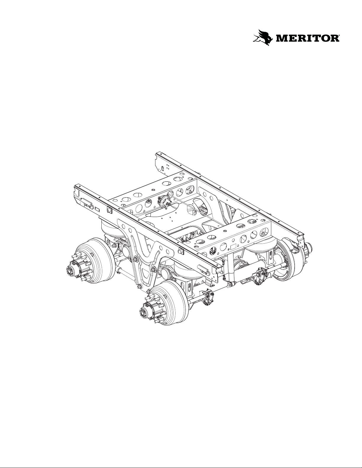
1 Exploded View
RideSentry™ MPA Series Sliding Tandem Trailer Air Suspension System
Figure 1.1
4006703a
14
13
20
6
4
5
5
19
19
7
18
17
15
21
23
24
10
9
16
8
8
2
22
3
2
1
1
10
12
11
7
9
Item Description
1Slider Wear Pad
2Slider Cross Member
3Meritor PinLoc™ System
4Slider Side Rail, Curbside
5Air Spring
6Lower Control Arm, Fixed
7Lower Bushing
8Lower Inner Sleeve, Bushing Inner Metal
9Upper Axle Seat
10 Upper Control Arm
11 Lower Axle Seat
12 Upper Bushing
13 Clevis, Shock
14 Axle Assembly, Rear
15 Height Control Linkage
16 Lower Shock Mounting Bracket
17 Shock Absorber
18 Height Control Air Valve (Hadley 1500
Series)
19 Lower Control Arm, Adjustable
20 Axle Assembly, Front
21 Suspension Tag
22 Slider Slide Rail, Roadside
23 Hold Down Clip
24 Lock Pin Operation Label
Item Description
2 Introduction
2Meritor Maintenance Manual 14R (Revised 12-18)
2 Introduction
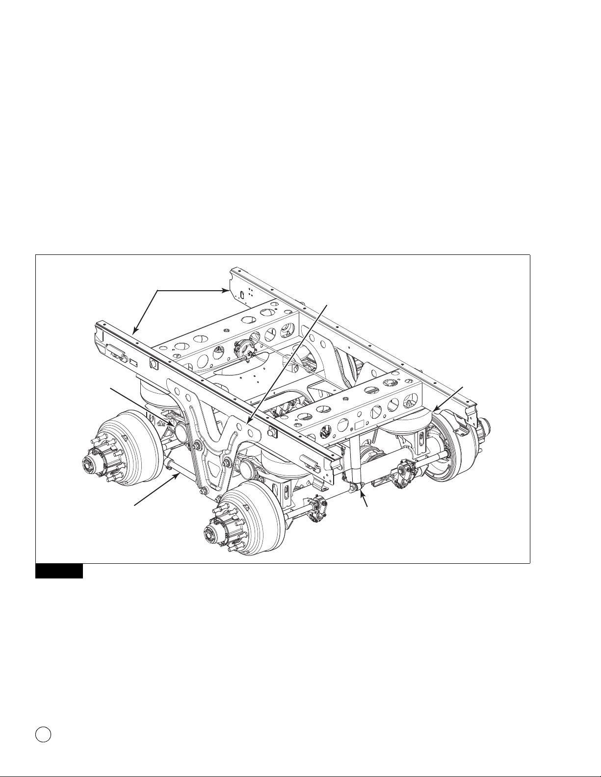
Description
The Meritor RideSentry™ MPA Series sliding tandem trailer air
suspension system centers around a stabilized parallelogram design
that incorporates a single unified frame bracket. The upper and
lower control arms are parallel to each other. The air springs mount
directly over the axle. Figure 2.1.
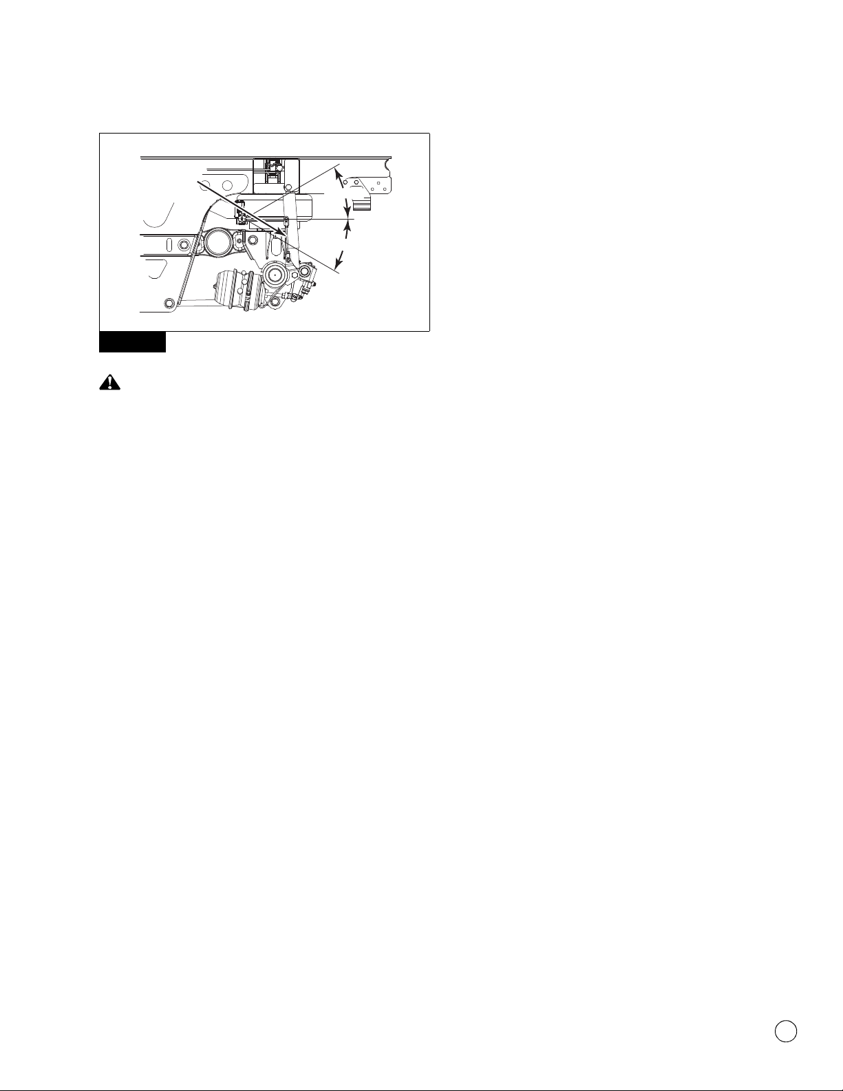
Ride height and mounting height are important measurements for
overall vehicle height. Measure ride height from the centerline of the
axle to the bottom of the slider frame. Measure mounting height
from the centerline of the axle to the bottom of the trailer frame.
Figure 2.2.
Figure 2.1
Figure 2.1
4006704a
FRAME
BRACKET
AIR
SPRING
SHOCK
ABSORBER
UPPER
CONTROL
ARM
LOWER
CONTROL
ARM
SLIDER
ASSEMBLY
CURBSIDE
ROADSIDE

2 Introduction
3
Meritor Maintenance Manual 14R (Revised 12-18)
Figure 2.2
Refer to the trailer manufacturer’s specifications for the correct ride
height. Note that the nominal ride height, also referred to as the
design height, refers to the designed ride height and may not be the
same as the actual ride height. To determine the nominal ride height
of the RideSentry™ suspension, the following indicators apply.
앫16.5-inch ride height has the air spring mounted directly to the
upper axle seat.
앫17.5-inch ride height has a 1.0-inch spacer under the air spring.
앫18.5-inch ride height has two 1.0-inch spacers under the air
spring.
Components
앫Frame brackets and slider assembly
앫Upper and lower control arms
앫Axle assemblies
앫Air springs
앫Shock absorbers
Features
앫A compact 38,000 and 40,000 lb (17 237 and 18 144 kg)
capacity tandem trailer air suspension and slider system
designed for sliding tandems.
앫Nominal ride heights of 16.5-inches (41.9 cm), 17.5-inches
(44.5 cm) and 18.5-inches (47.0 cm) are offered with eight
inches (20.3 cm) of total travel for the 16.5- and 17.5-inch ride
heights. The 18.5-inch ride height has seven inches of total
travel.
앫A mounting height of 24.5-26.5-inches (62.2-67.3 cm).
Figure 2.2
4006705a
LOCKING PIN
SLIDER
RIDE
HEIGHT
MOUNTING
HEIGHT
ROADSIDE
AXLE

2 Introduction
4Meritor Maintenance Manual 14R (Revised 12-18)
Identification
The identification tag is located on the roadside of the suspension
near the front of the slider side rail. Figure 2.3.
Figure 2.3
The model number on the identification tag provides suspension and
axle information. Figure 2.4.
Figure 2.4
Figure 2.3
Figure 2.4
STAMPED INFORMATION
Suspension Capacity
Nominal Ride Height
Model Number
Serial Number
FOR SUSPENSION NOMINAL RIDE HEIGHT
(NRH), REFERTOTHE NRH VALUE INDICATED
ONTHIS LABEL. FORTHE ACTUAL RIDE
HEIGHT VALUE, REFERTOTHE VEHICLE/
TRAILER MANUFACTURER'S SPECIFICATION
SUSP. CAP.
MODEL SERIAL NO.
LB. IN.
NRH
C
A
B
C
D
AB
D
4006707a
ROADSIDE
IDENTIFICATION
TAG
MPA XX S XX XX XXXX
Suspension Model
Axle Type
Nominal Ride Height
Sliding Subframe
Suspension Rating x 1000 lbs.
Sequence Number:
Can be cross
referenced to the
Bill of Material.
4006708a
Nominal Ride Height
65 16.5-inches
75 17.5-inches
85 18.5-inches

3 Inspection and Maintenance
5
Meritor Maintenance Manual 14R (Revised 12-18)
3 Inspec tion and Maint enance
Hazard Alert Messages
Read and observe all Warning and Caution hazard alert messages in
this publication. They provide information that can help prevent
serious personal injury, damage to components, or both.
WARNING
To prevent serious eye injury, always wear safe eye protection
when you perform vehicle maintenance or service.
Check fastener torque values, tighten loose fasteners and
replace damaged fasteners. Loose, damaged or missing
fasteners can cause loss of vehicle control, serious personal
injury and damage to components.
Refer to Section 8 for the torque values.
Inspection
Inspect the suspension, air suspension components, height control
valve and axle at regular intervals during normal operation and each
time the trailer is serviced.
앫Before each trip, visually inspect the system. Listen for air leaks.
After 1,000 Miles (1600 km) and Annually Thereafter
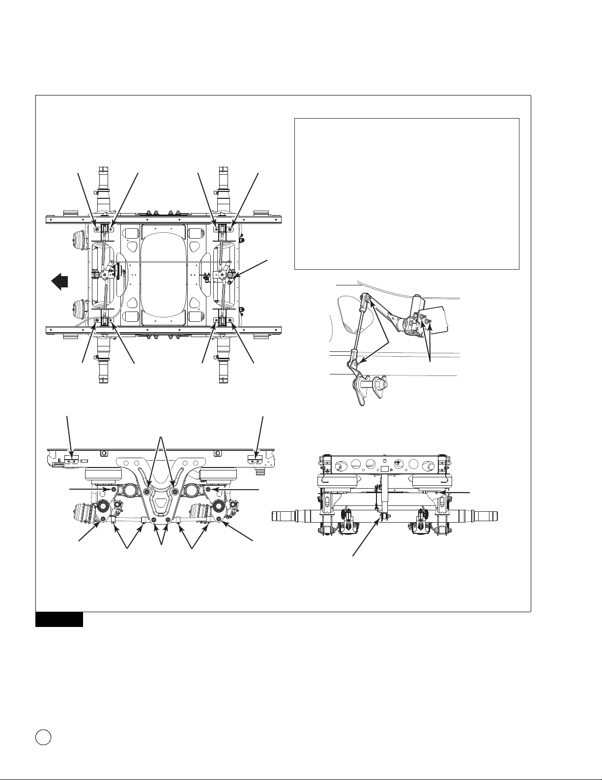
1. Visually inspect all fasteners for looseness or movement.
Figure 3.1. Ensure loose fasteners have not caused damage to
any suspension components. Tighten loose fasteners to the
correct torque specified in Section 8.
앫Replace any damaged components and fasteners. Refer to
Section 4 for component removal and installation
procedures.
앫If a loose pivot bolt is at an upper control arm pivot
connection: Disassemble the pivot joint at the loose
fastener location. Refer to “Upper Control Arm” in Section 4
for the procedures.
2. Replace damaged fasteners to maintain the correct torque
specifications to comply with warranty requirements. Refer to
Section 8.
3. Visually inspect the upper control arm bushings for ragged or
loose pieces that can protrude from the pivot connection area.
Damage to components can result.
앫If the upper control arm bushings are ragged or have
loose pieces that protrude from them: Replace the
bushings. Refer to Section 4 for the upper control arm
bushing removal and installation procedures.
3 Inspection and Maintenance
6Meritor Maintenance Manual 14R (Revised 12-18)
Figure 3.1
Figure 3.1
1. Upper Control Arm, Axle End
2. Upper Control Arm, Frame Bracket End — Roadside
3. Upper Control Arm, Frame Bracket End — Curbside
4. Lower Control Arm — Fixed, Axle End
5. Lower Control Arm — Fixed, Frame Bracket End
6. Lower Control Arm — Adjustable, Axle End
7. Lower Control Arm — Adjustable, Frame Bracket End
8. Lower Control Arm — Adjustable, Clamp Bolt
9. Upper Air Spring Nut, 3/4-16 NF
10. Upper Air Spring Nut, 1/2-13 NC
11. Lower Air Spring Nut
12. Shock Absorber — Upper and Lower
13. Height Control Linkage — Upper and Lower
14. Height Control Valve Mounting Bolt
15. Slider Hold Down Clip
ROADSIDE
BOLT KITS
ROADSIDE
910 109
91010 9
14
13
11
12
6/4
8
7/5*
8
6/4
15
2/3*
1
1
15
12
*CURBSIDE SIMILAR
4006709a
CURBSIDE
FRONT
3 Inspection and Maintenance
7
Meritor Maintenance Manual 14R (Revised 12-18)
Maintenance
Slider
1. Inspect for loose, broken or missing fasteners. Repair or
replace as needed. Refer to Section 8 for the correct torque
specifications.
2. Check the slider locking pins and slider wear pads for signs of
excessive wear or binding. Figure 3.2. Repair or replace as
needed.
3. Inspect the structure of the slider box and crossmembers for
damage. Repair as needed.
4. Inspect the front and rear hold down clips to ensure that they
are secured correctly around the body rails.
Figure 3.2
Figure 3.2
4006710a
WEAR PAD
WEAR PAD
HOLD DOWN
CLIP
LOCKING
PIN

3 Inspection and Maintenance
8Meritor Maintenance Manual 14R (Revised 12-18)
Trailer Air Suspension
1. Inspect for loose, broken or missing fasteners. Repair or
replace as needed. Refer to Section 8 for the correct torque
specifications.
2. Inspect the welds for cracks at the axle, frame bracket and
upper control arm crosstube.
3. Inspect the bushings for ragged or loose pieces that can
protrude from the connection area.
앫If the condition exists: Contact the Meritor OnTrac™
Customer Call Center at 866-668-7221.
4. Inspect the flex member of the air springs for cuts and
abrasions. Replace the air spring if it is cut or damaged.
5. Check for obstructions or interference to the air spring surface
that can damage the air spring. Relocate and secure items,
such as air hoses, that can contact the air spring.
6. Check for leaks in the air lines at the air spring bead plate,
piston and mounting studs. Replace air lines, fittings or air
springs that leak. Refer to Section 4.
7. Inspect the shock absorbers for worn bushings, oil leaks and
dents. Check that the mounting holes have not enlarged.
8. After normal operation, check the shock absorbers for heat.
앫Warm shock absorbers most likely indicate that the shock
absorbers are operating correctly.
앫Cold shock absorbers can indicate that the shock absorbers
are not operating correctly and must be replaced. Replace
the shock absorbers as necessary.
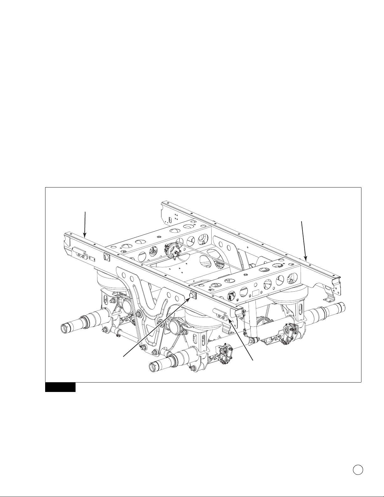
9. Inspect the structure of the suspension. Figure 3.3. Inspect the
following items.
앫Upper axle seats
앫Upper control arms
앫Lower axle seats
앫Lower control arms
앫Axle welds
앫Brake interference, cam or chamber
앫Frame brackets
앫Shock absorber brackets
Figure 3.3
Inspection
Height Control Valve
There are three basic configurations for plumbing the height control
valve (HCV) into the air suspension system.
앫No-dump
The no-dump configuration is standard equipment. In the
no-dump configuration, the valve maintains air pressure and
enables the trailer to maintain ride height during loading and
unloading, if it is attached to an air supply.
앫Auto-dump
The auto-dump configuration will exhaust the air springs when
the trailer parking brakes are set. This lowers the trailer deck
height three-inches providing a stable platform for loading and
unloading. The trailer will return to the ride height when the
parking brakes are released.
앫Manual-dump/auto-reset
The manual-dump/auto-reset configuration offers the same
feature as auto-dump, except at the operator’s discretion.
WARNING
Park the vehicle on a level surface. Block the wheels to
prevent the vehicle from moving. Support the vehicle with
safety stands. Do not work under a vehicle supported only by
jacks. Jacks can slip and fall over. Serious personal injury and
damage to components can result.
1. Park the unloaded vehicle on a level surface. Block the wheels
to prevent the vehicle from moving.
2. Disconnect the height control linkage. Figure 3.4.
Figure 3.3
4006711a
UPPER
AXLE
SEAT
LOWER
AXLE
SEAT
LOWER
CONTROL
ARMS
UPPER
CONTROL
ARM
FRAME
BRACKET
3 Inspection and Maintenance
9
Meritor Maintenance Manual 14R (Revised 12-18)
Figure 3.4
WARNING
Verify that all personnel are clear of the trailer before you
inflate or deflate the air springs. The air suspension system
has various pinch points that can cause serious personal
injury.
3. Check the air supply to the height control valve. A minimum of
65 psi (448 kPa) is required to correctly test the height control
valve.
4. Rotate the lever UP 30 to 45 degrees. Air should begin to flow
into the air springs.
5. Rotate the lever to the neutral position. Airflow should stop.
6. Rotate the lever DOWN 30 to 45 degrees. Air should begin to
flow out of the air springs.
7. Rotate the lever to the neutral position. Airflow should stop.
앫If the air does not flow to and from the air springs:
Drain the air from the system. Use compressed air to clean
the screens in the supply and delivery ports.
8. Connect the air lines to the height control valve and repeat the
above steps.
앫If air still does not flow to and from the air springs, or if
the airflow cannot be stopped in the neutral position:
Replace the height control valve.
9. Inspect the height control valve for air leaks and a cracked
lever arm housing.
앫If air leaks or cracks are detected: Replace the height
control valve.
Axle Inspection and Maintenance
For correct inspection and maintenance procedures and intervals,
refer to Maintenance Manual 14, Trailer Axles. To obtain this
publication, refer to the Service Notes page on the front inside cover
of this manual.
Lubrication
The RideSentry™ MPA Series slider box or suspension does not
require lubrication. For lubrication and maintenance requirements
for axles, hubs and brakes, refer to Maintenance Manual 14, Trailer
Axles; and Maintenance Manual 1, Preventive Maintenance and
Lubrication. To obtain these publications, refer to the Service Notes
page on the front inside cover of this manual.
Figure 3.4
4006712a
HEIGHT
CONTROL
LINKAGE 30°-45°
30°-45°
4 Component Removal, Installation and Adjustment
10 Meritor Maintenance Manual 14R (Revised 12-18)
4 Compone nt Removal, Installatio n and Adjustment
Hazard Alert Messages
Read and observe all Warning and Caution hazard alert messages in
this publication. They provide information that can help prevent
serious personal injury, damage to components, or both.
WARNING
To prevent serious eye injury, always wear safe eye protection
when you perform vehicle maintenance or service.
Park the vehicle on a level surface. Block the wheels to
prevent the vehicle from moving. Support the vehicle with
safety stands. Do not work under a vehicle supported only by
jacks. Jacks can slip and fall over. Serious personal injury and
damage to components can result.
Verify that all personnel are clear of the trailer before you
inflate or deflate the air springs. The air suspension system
has various pinch points that can cause serious personal
injury.
Removal and Installation
Height Control Valve (HCV)
1. Park the unloaded vehicle on a level surface. Block the wheels
to prevent the vehicle from moving.
2. Drain all the air from the surge tank and air springs.
3. Remove the air supply and delivery lines from the height
control valve.
4. Disconnect the linkage. Replace bent or damaged linkage.
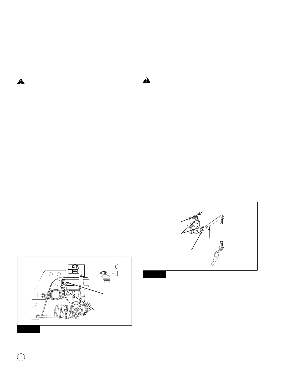
5. Remove the height control valve from the bracket. Figure 4.1.
Figure 4.1
6. Install the new HCV onto the mounting bracket. Tighten the
mounting bolts to 5 lb-ft (7 N폷m). @
7. Connect the linkage. Tighten the upper and lower linkage bolts
to 5 lb-ft (7 N폷m). @
CAUTION
The Hadley 1500 HCV is equipped with 3/8-inch (9.525 mm)
push-to-connect fittings. Do not use sealant on
push-to-connect fittings. Damage to components can result.
8. Connect the air supply and the delivery lines to the height
control valve.
9. Charge the air system.
10. Use a soapy spray solution to check the entire system for air
leaks.
11. Verify the ride height setting. Refer to the procedures in this
section.
HCV Installation Options
The suspension may be equipped with a 1500 Series auto-dump
configuration or a 1500 Series no-dump configuration. Figure 4.2
and Figure 4.3.
Figure 4.2
Figure 4.1
4006713a
HEIGHT
CONTROL
VALVE
MOUNTING
BRACKET
Figure 4.2
4006714a
LEVER
SUPPLY PORT
DUMP PILOT
PORT
SUSPENSION
PORT
BOLT TORQUE
50-55 LB-IN
(6 N•m)
AUTO-DUMP

4 Component Removal, Installation and Adjustment
11
Meritor Maintenance Manual 14R (Revised 12-18)
Figure 4.3
Adjustment
Verify Ride Height
1. Refer to the trailer manufacturer’s specifications for the correct
ride height.
2. Unload the vehicle before you adjust the height control valve.
Support the trailer king pin at the normal operating height.
3. Verify the correct ride height by measuring the ride height from
the axle centerline to the bottom of the slider frame.
앫If the measured ride height does not meet the trailer
manufacturer’s specifications: Continue to the next step.
앫If the measured ride height does meet the trailer
manufacturer’s specifications: Go to Step 10.
4. Disconnect the height control valve linkage from the lever arm.
Inflate or deflate the air springs by raising or lowering the
height control lever arm 30 to 45 degrees. Hold the lever arm
in the UP position for at least 15 seconds or until the air bags
are correctly inflated. Figure 4.4.
Figure 4.4
5. Check the ride height. Figure 4.5. Repeat the previous step
until the measured ride height matches the trailer
manufacturer’s specified ride height.
Figure 4.5
6. Use a 3/8-inch wrench to loosen the 0.25-inch adjusting screw
located on the lever arm body. Allow the lever arm to swing
free.
7. Align the end of the lever arm to the top opening of the linkage.
Loosely insert the upper linkage bolt.
8. Tighten the 0.25-inch adjusting screw to 50-55 lb-in
(6 N폷m). @
9. Connect the upper linkage bolt. Tighten the bolt to 5 lb-ft
(7 N폷m). @
10. Verify that the overall trailer height does not exceed the local
legal limit.
앫If the ride height is not within the specification: Repeat
the ride height adjustment procedure until the ride height is
correct.
Maintain the Correct Ride Height When You
Change an HCV
You must maintain the correct ride height when you change an HCV.
Refer to the trailer manufacturer’s specifications for the correct ride
height.
Figure 4.3
Figure 4.4
4006715a
LEVER
BOLT TORQUE
50-55 LB-IN
(6 N•m)
NO-DUMP SUPPLY PORT
SUSPENSION
PORT
4006716a
HEIGHT
CONTROL
VALVE
LINKAGE
ADJUSTING
SCREW
Remove
this bolt.
30°-45°
INFLATE
DEFLATE
30°-45°
Figure 4.5
4006717a
MOUNTING
HEIGHT
RIDE
HEIGHT
4 Component Removal, Installation and Adjustment
12 Meritor Maintenance Manual 14R (Revised 12-18)
Removal and Installation
Air Spring
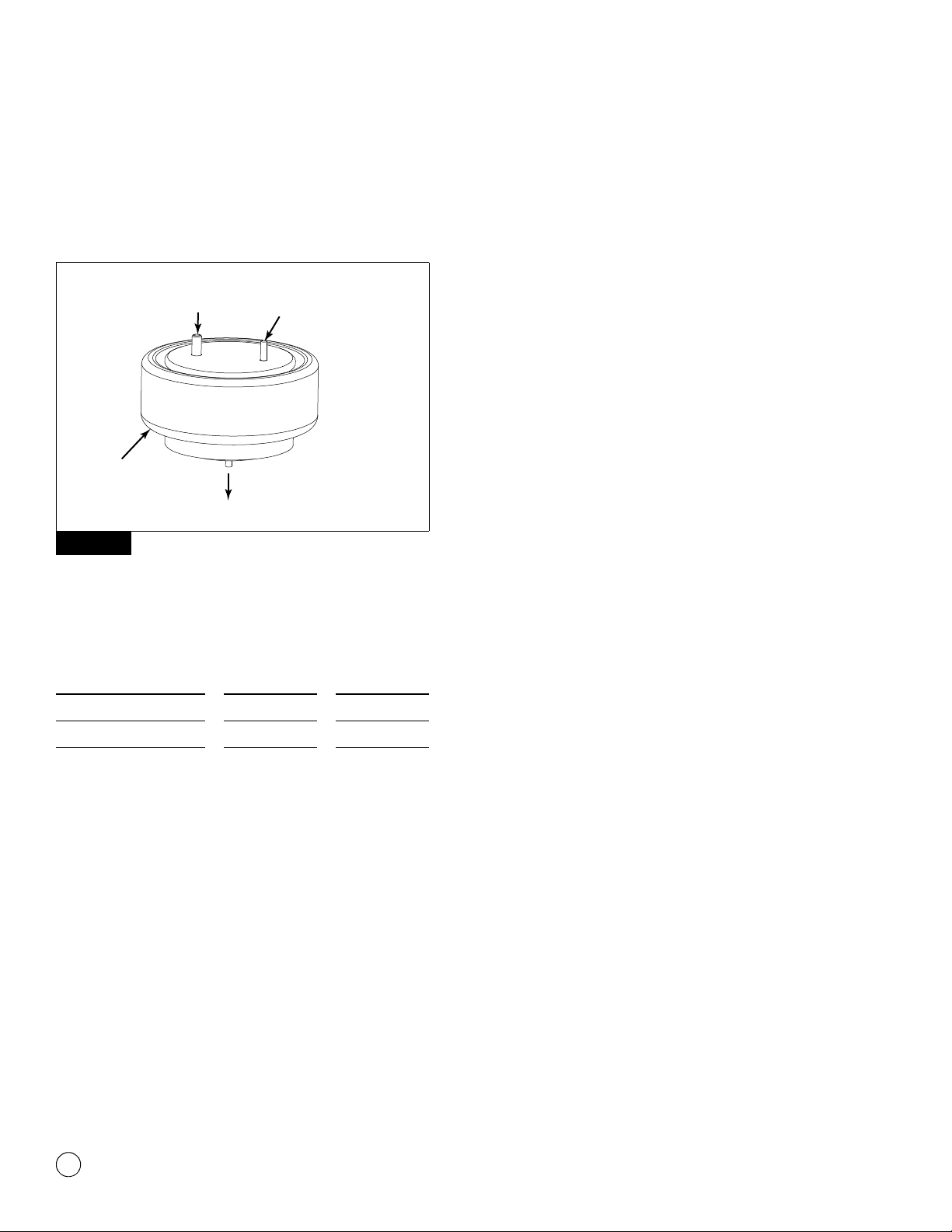
Figure 4.6 shows the standard air spring used on the suspension.
Figure 4.6
The RideSentry™ suspension uses three different air springs based
on the suspension model and ride height. Refer to the following
table for the air spring part numbers.
1. Refer to the preceding table to identify the specific air spring
that is damaged or leaking air.
2. Park the trailer on a level surface. Block the tires to prevent the
trailer from moving.
3. Use an appropriate lifting device to raise the trailer to extend
the air springs, but not enough to raise the tires off the ground.
Support the trailer with safety stands.
4. Verify that all the air has been exhausted from the air system.
5. Remove the air inlet line and fitting from the damaged air
spring. Figure 4.7.
Figure 4.6
Air Spring
Suspension
Model Ride Height
A-2258-F-1410 MPA38/40 16.5
A-2258-W-1531 MPA38/40 17.5
A-2258-X-1532 MPA38/40 18.5
AIR SUPPLY
FITTINGTO SLIDER
FRAME
TO UPPER AXLE SEAT
AIR
SPRING
4002674a
4 Component Removal, Installation and Adjustment
13
Meritor Maintenance Manual 14R (Revised 12-18)
Figure 4.7
6. Remove the nuts from the studs that secure the top of the air
spring.
7. Remove the nut from the bottom of the air spring. You can
reach the nut from inside the front or rear of the upper axle
seat.
8. Compress the air spring. Remove the spring from the
suspension.
9. Compress the new air spring. Slide the spring into the space
between the axle seat and slider frame. Reuse the air spring
spacer(s), if originally supplied.
10. Align the air inlet and mounting stud. Insert them into the holes
in the slider frame.
11. Install the lower nut. Tighten the lower nut to 30-35 lb-ft
(41-47 N폷m). @
12. Install the nuts on the top mounting studs. Tighten the 1/2-13
UNC nut to 20-25 lb-ft (30-35 N폷m). Tighten the 3/4-16 UNF
nut to 45-50 lb-ft (60-70 N폷m). @
13. Install the fitting and inlet air line to the top of the air spring.
Apply a sealant tape.
14. Seat the valve at the bottom of the air tank. Pressurize the air
system.
15. Check that items such as tires, air lines or suspension
components do not interfere with the air spring flex members.
16. Use a soap solution to check the entire system for air leaks.
17. Raise the trailer. Remove the safety stands.
18. Verify that the ride height of the trailer is correct.
앫If the ride height is incorrect: Adjust the height control
lever arm to obtain the correct ride height. Refer to the
trailer manufacturer’s specifications for the correct ride
height.
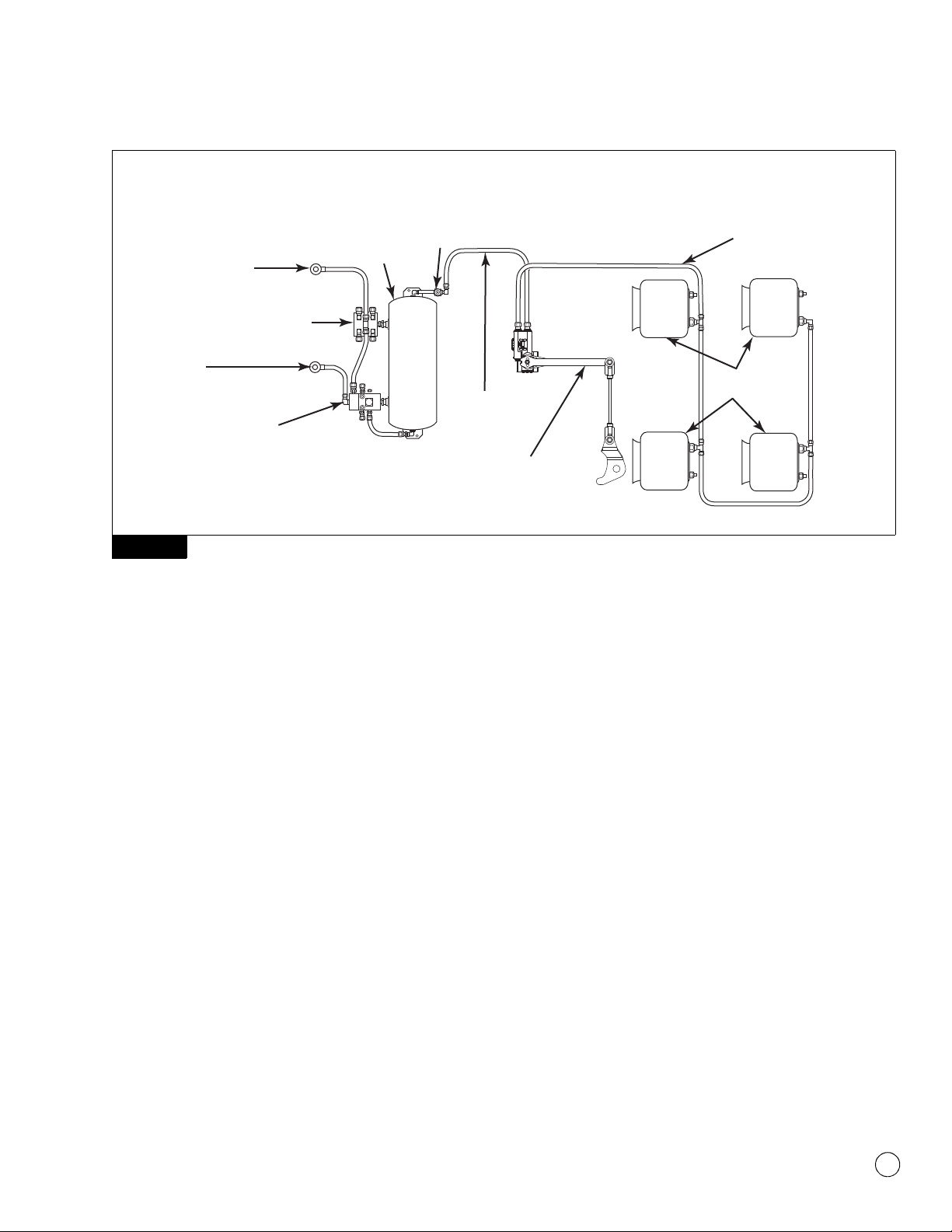
Figure 4.7
BRAKE
PROTECTION
VALVE
PILOT
RELAY
VALVE
4006718a
CURBSIDE
ROADSIDE
TO
AIR SPRINGS
AIR
SPRINGS
TRAILER
SPRING
BRAKE
VALVE
GLAD HAND
SUPPLY
EMERGENCY
PARKING,
RED
GLAD
HAND
CONTROL,
BLUE
AIR
RESERVOIR
FROM BRAKE
PROTECTION
VALVE
HEIGHT CONTROL
VALVE

4 Component Removal, Installation and Adjustment
14 Meritor Maintenance Manual 14R (Revised 12-18)
Upper Control Arm
WARNING
Visually inspect upper control arm fasteners to ensure they are
tightened to the correct specification. Loose fasteners can
damage suspension components. If you find a loose pivot bolt
at the upper control arm pivot connection, disassemble the
pivot joint to check for damaged components. Tighten loose
fasteners. Replace damaged fasteners and components to
prevent serious personal injury and damage to components
during operation.
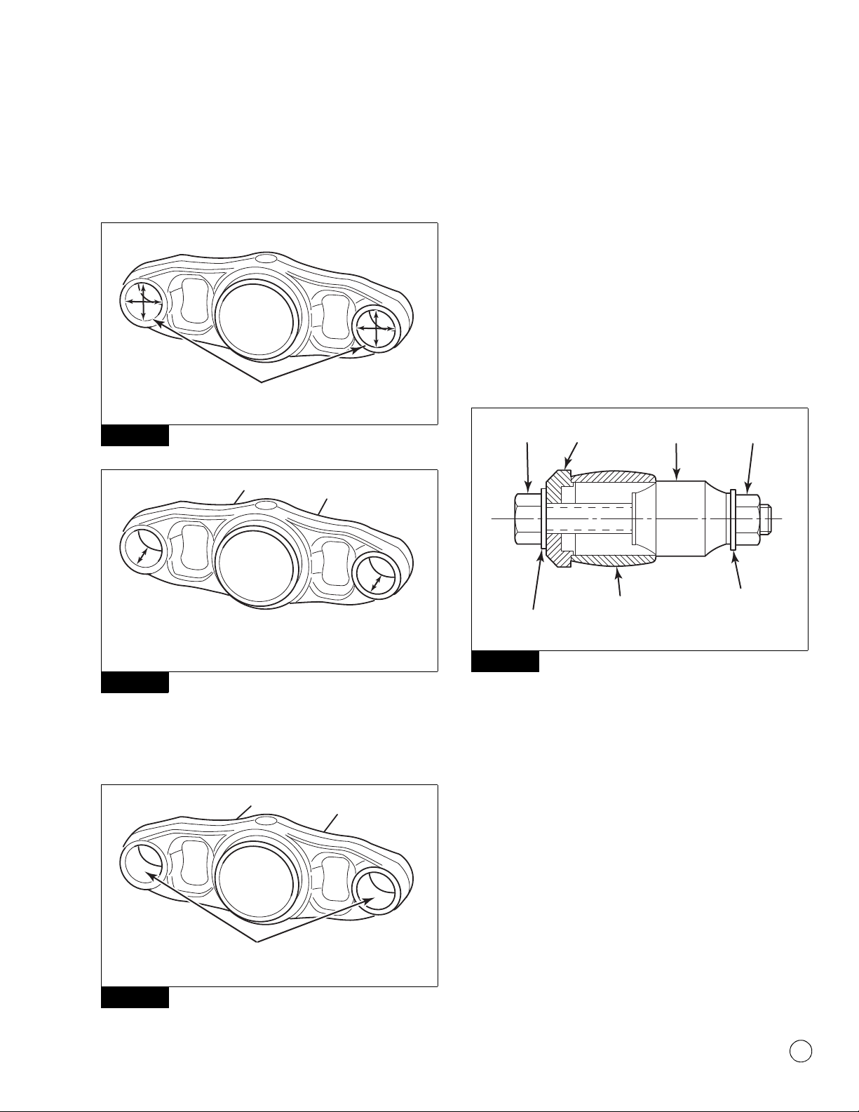
Visually inspect the upper control arm bushing inner metal ends for
wear. Wear is not permitted between the bushing inner metal and its
mating surfaces. Refer to Figure 4.8.
앫If there is wear between the bushing inner metal and its
mating surface: Replace the upper control arm bushing at the
loose fastener location only.
앫If a loose fastener is at the frame hanger location and
damage is found: Use a roadside or curbside side plate repair
kit.
앫If a loose fastener is at the upper axle seat and damage is
found: Replace the upper axle seat. Contact the Meritor
OnTrac™ Customer Call Center at 866-668-7221 for parts and
kits.
Figure 4.8
1. Lower the landing gear. Use an appropriate lifting device to
raise the trailer frame so that the tires are off the ground.
Support the trailer with safety stands. Set the parking brake.
2. Exhaust the air pressure from the suspension air springs.
Remove the wheels from the axle where you are removing the
bushings to access the pivot bolts.
앫If there is corrosion between the pivot bolts and the
bushing inner metal: Use an impact wrench to spin the
pivot bolt heads at all four connections to disengage the
bolts from the corrosion to the bushing inner metal.
3. Remove only the locknut at the frame bracket on the roadside
and curbside at the upper pivot connections.
4. Record the pivot bolt orientation. Remove the pivot bolts from
the frame brackets. Slide the upper control arm out of the
frame brackets to provide access to the bushings.
5. Remove the bushings. Remove any burrs and clean the inside
diameter of the upper control arm ends. Figure 4.9.
Figure 4.9
6. Visually inspect the upper control arm bushing tubes, frame
brackets and axle seats.
A. You must measure the bore diameter and bushing tube
length of all four upper control arm bushing tubes before
you install the new bushings. The bore diameter must be
2.240-2.250-inches (56.896-57.150 mm). Figure 4.10.
The bushing tube length must be 2.530-inches
(64.262 mm) or greater. Figure 4.11.
앫If any of the four upper control arm bushing tubes
are not within the specifications: Replace the upper
control arm.
Figure 4.8
No wear is permitted
between the bushing
inner metal and its
mating surfaces.
4005083c
BUSHING
THRUST
WASHER
THRUST
WASHER
BUSHING
INNER
METAL
UPPER CONTROL ARM
BUSHING TUBE
Figure 4.9
4006737a
Inspect and
remove burrs.
4 Component Removal, Installation and Adjustment
15
Meritor Maintenance Manual 14R (Revised 12-18)
B. Inspect the frame brackets and axle seats for wear from
contact with the upper control arm bushing inner metal.
Wear is not permitted between the bushing inner metal
and its mating surfaces.
Figure 4.10
Figure 4.11
7. Using light mineral oil, Meritor specification O-92-B, lightly
lubricate the inside diameter of the upper control arm bushing
tubes. Figure 4.12.
Figure 4.12
8. Refer to Section 9 for a description of the bushing tool part
number A-3256-H-1152.
9. Using light mineral oil, Meritor specification O-92-B, lightly
lubricate the outside diameter of the bonded bushing.
10. Place the draw plate onto the inside surface of the upper
control arm bushing tube. Figure 4.13.
A. Insert the draw bolt with a flat washer, through the draw
plate and bushing tube.
B. Place the bushing over the draw bolt and into the upper
control arm bushing tube.
C. Thread the draw nut and flat washer onto the draw bolt
until it sets against the bushing.
Figure 4.13
11. Snug the draw bolt while ensuring that the bushing and draw
plate rest securely on the upper control arm bushing tube.
12. While holding the draw nut with a wrench, turn the draw bolt
CLOCKWISE using a maximum one-half-inch impact at a
reduced and steady speed. Draw the bonded bushing into the
upper control arm bushing tube.
13. If the bolt stops turning or extreme resistance is present,
reverse the impact and loosen the tool assembly. Inspect all
components of the tool for damage. Reset the draw plate
ensuring that the bonded bushing is correctly seated against
the upper control arm bushing tube. Verify lubrication on the
bushing and control arm tube and repeat the above procedure.
14. Continue rotating the draw bolt until the bolt stops turning and
the bushing is fully inserted. Thread damage to the draw bolt or
draw nut can occur if over tightened.
Figure 4.10
Figure 4.11
Figure 4.12
4006738a
Check both ends
of each tube.
4006739a
4006740a
LUBRICATED
SURFACE
Figure 4.13
4005082b
DRAW
BOLT
FLAT
WASHER
FLAT
WASHER
UPPER CONTROL
ARM BUSHING
TUBE
DRAW
PLATE
DRAW
NUT
BUSHING

4 Component Removal, Installation and Adjustment
16 Meritor Maintenance Manual 14R (Revised 12-18)
15. Ensure that the bushing is centered in the upper control arm
bushing tube from side-to-side. Install the thrust washers onto
the bushings. Figure 4.14.
Figure 4.14
16. Position the upper control arm into the frame brackets. Ensure
that the thrust washers remain in position on the bushings.
Using the recorded pivot bolt orientation, insert a new pivot
bolt, flat washers, alignment washers and nut on the roadside.
Insert a new pivot bolt, flat washers and nut on the curbside.
Figure 4.15.
Figure 4.15
17. Loosely install the roadside and curbside nuts. Do not
completely tighten at this time.
18. Remove only the locknuts at the upper axle seat on the
roadside and curbside upper pivot connections.
19. Remove the pivot bolts from the upper axle seats. Record the
pivot bolt orientation. Slide the upper control arm out of the
upper axle seats to provide access to the bushings.
20. Remove the bushings. Remove any burrs and clean the inside
diameter of the upper control arm ends. Figure 4.9.
21. Repeat Steps 7-15 to install the bushing.
22. Position the upper control arm into the upper axle seats.
Ensure that the thrust washers remain in position on the
bushings. Using the recorded pivot bolt orientation, insert a
new pivot bolt, flat washers and nut on the roadside and
curbside.
23. Loosely install the nuts at the axle seat positions. Do not
completely tighten at this time.
24. Determine the correct suspension ride height. Refer to the
trailer manufacturer’s specifications. The upper control arm
must be at the correct ride height before applying the required
torque to all upper pivot bolts. Figure 4.16.
Figure 4.16
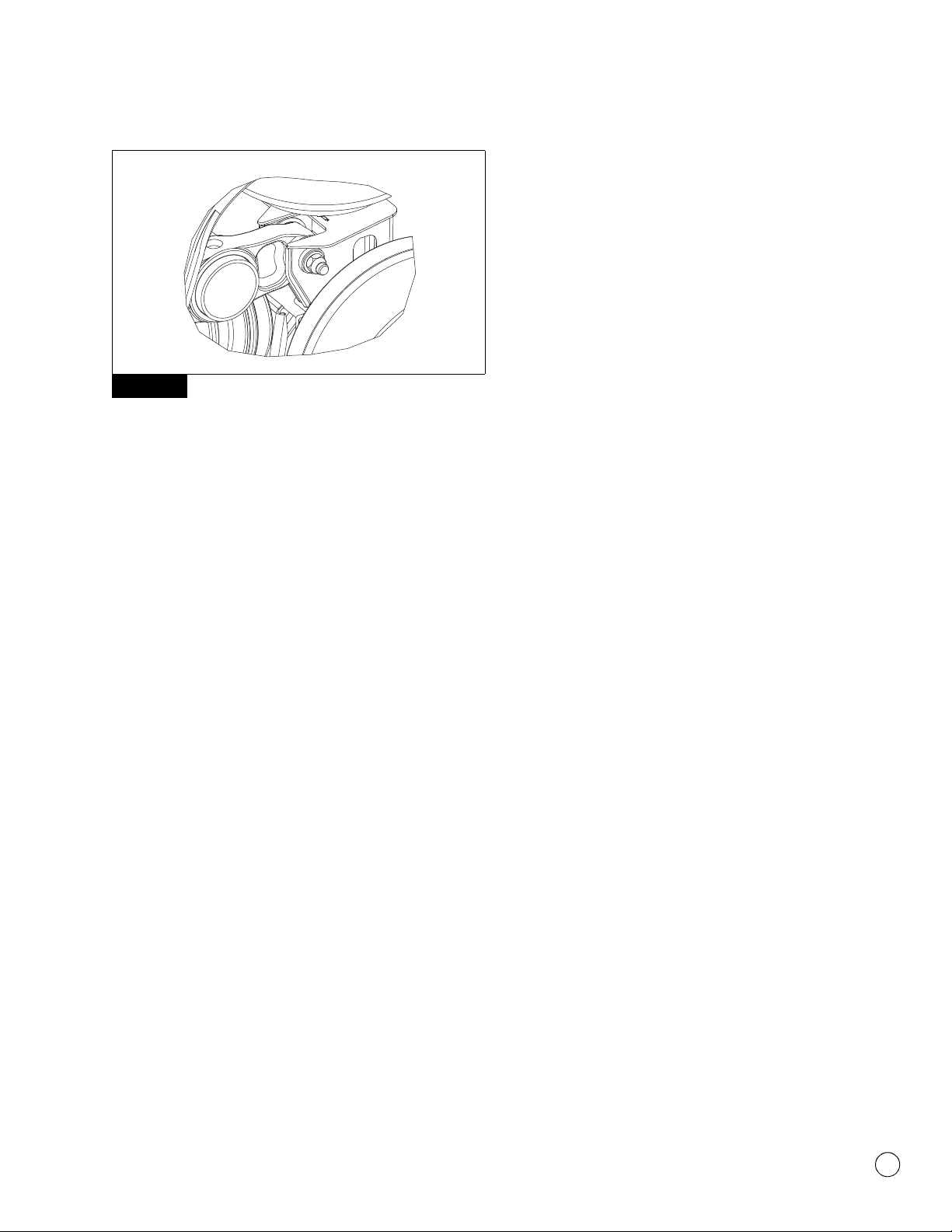
25. Install the locknut and tighten to 450-500 lb-ft (611-678 N폷m).
Figure 4.17. @
Figure 4.14
Figure 4.15
4005083b
BUSHING
THRUST
WASHER
THRUST
WASHER
BOTH
DIMENSIONS
SHOULD BE
THE SAME
± 0.010" (0.25 MM)
UPPER CONTROL ARM
BUSHING TUBE
4005084a
PIVOT
NUT
PIVOT
BOLT
FLAT
WASHER
FLAT
WASHER
FRAME
BRACKET/AXLE
SEAT
UPPER CONTROL ARM
BUSHING TUBE
THRUST
WASHERS
Figure 4.16
4006719a
MOUNTING
HEIGHT
RIDE
HEIGHT
AXLE
4 Component Removal, Installation and Adjustment
17
Meritor Maintenance Manual 14R (Revised 12-18)
Figure 4.17
26. Reinstall the wheels and tires. Remove the safety stands at the
rear of the trailer. Slowly lower the trailer back down onto the
suspension.
27. Check the suspension ride height to verify it is correct. If
adjustment is necessary, refer to the ride height adjustment
procedures in this section.
28. Axle realignment is required. Refer to the axle alignment
procedures in this section.
29. Refer to Section 8 for torque specifications.
Lower Control Arm
1. Park the trailer on a level surface.
2. Lower the landing gear. Use an appropriate lifting device to
raise the rear of the trailer frame so that the tires are off the
ground. Support the trailer with safety stands.
3. Exhaust the air pressure from the suspension air springs.
Remove the wheels from the axle to access the pivot bolts.
앫If there is corrosion between the pivot bolts and
bushing inner metal: Use an impact wrench to spin the
pivot bolt heads at all four connections to disengage the
bolts from corrosion to the bushing inner metal.
4. Remove the locknuts from the pivot bolts at the frame bracket
and lower axle seat.
5. Remove the pivot bolts. Remove the lower control arm.
6. Remove the bushings and inner sleeves. Remove any burrs
and clean the inside diameter of the lower control arm ends.
7. Insert new bushings into the lower control arm ends. Insert the
inner sleeve through the bushings. Use light mineral oil, Meritor
specification O-92-B for lubrication. Center the inner sleeve in
the lower control arm ends.
8. Position the lower control arm into the frame bracket and lower
axle seat. Insert a new bolt, flat washers and nut at both pivot
connections.
9. Tighten the nuts to 450-500 lb-ft (611-678 N폷m). @
Axle Replacement Procedure
1. Park the trailer on a level surface. Lower the landing gear.
2. Use a jack to raise the rear of the trailer frame, until the tires on
the axle you will replace just clear the floor. Support the trailer
with safety stands.
3. Exhaust the air pressure from the suspension air springs and
air tank.
4. Remove the drums, tires and wheel ends, preferably all
together.
5. Remove the brake shoes.
6. Disconnect the brake chamber clevis from the automatic slack
adjuster.
7. Disconnect the brake chambers from the axle and secure them
out of the way. It is not necessary to disconnect the brake
hoses.
8. Remove the automatic slack adjusters.
9. Remove the bottom retaining nut from the suspension air
springs.
10. Use a jack to raise the axle up about four inches (101.2 mm).
Stabilize the axle. Remove the bottom bolt from the shock
absorber/axle connection.
앫If you are servicing a rear axle: Move the leveling valve
control rod UP and out of the way.
11. Remove the lower control arm nuts, pivot bolts and washers at
the axle seat. Move the lower control arms DOWN and out of
the way.
12. Remove the upper control arm nuts, bolts and washers at the
axle seat connection on each side.
13. Remove axle from under the trailer.
Figure 4.17
4006720a
Table of contents
Other Meritor Automobile Accessories manuals


