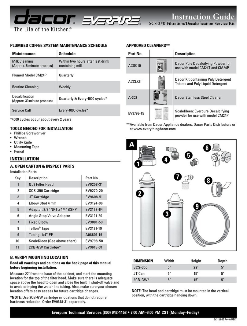
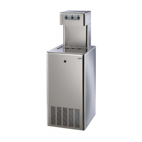
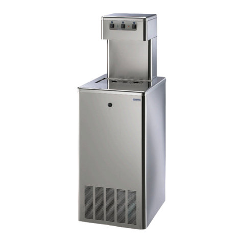
MERQUIP Cosmetal J Class 30 Manual

1
Installation, use and maintenance handbook
COD: 5561351
REV.4:0112
30 / 45
GB
1

MANUFACTURER
Mod. ..................
..........V ..........Hz ..........W ..........A
Freon R134a kg............. Classe T
MADE IN ITALY
WATER COOLERS
1 Model
2 Supply
voltage
3 Quantity
of
cooling
gas
4 Class
5 Total
absorption
6 Frequency
7 Serial
number
8 Construction
year-month
APPLIANCE DATA PLATE
000100 0102
CONFORMANCE
STATEMENT
This appliance has been manu-
factured with suitable materials
for use with drinking water. The
device conforms to L.D. 108 dated
25.01.1992. The appliance has
been approved by the WRAS (WA-
TER REGULATION ADVISORY
SCHEME).
.
This product has been designed,
manufactured and placed on the
market complying with the following
EC conformities:
• safety requirements of the “Low
Voltage” 2006/95/CEE
• protection requirements of
“EMC” Directive, 2004/108/CEE
Certied by Nemko
.
6
5
1
2
3
784
• Keep this book for later use.
• When you have removed the packaging, make sure that the appliance is not
damaged. Any damage must be reported to your carrier within 24 hours.
In order to use your appliance to its best, we advise reading these
instructions carefully as they contain useful information.
• Make sure that installation and electrical wiring are carried out by a qualied
technician according to the manufacturer’s instructions and to the local norms in
force. The electrical system must be equipped with an effective earth according
to the law (46/90).
1.2 GENERAL PRECAUTIONS AND SUGGESTIONS
• Do not pull on the supply cable in order to remove the plug from the socket.
• When the appliance has been installed, make sure it is not resting on the mains
supply cable.
1.1 WARNINGS
1 BEFORE USING THE APPLIANCE
GB
If the machine has been put down or turned upside down, wait
for at least 8 hours before putting it into operation
Before carrying out any maintenance or cleaning operation,
remove the plug from the mains socket.
The data and characteristics indicated in this manual do not
bind the manufacturer, who reserves the right to make all the
modications deemed necessary, without having to give prior
notice or replacement.
2

1 BEFORE
USING
THE
APPLIANCE
GB
Failure
to
comply
with
any
of
these
safety
regulations
could
cause
res,
electric
shocks
or
damage
the
machine
• PLACEOFINSTALLATION
• Do
not
place
the
machine
near
inammable
solvents
such
as
alcohol
or
diluents.
• Do
not
install
the
machine
in
excessively
damp
and
dusty
places,
exposed
to
direct
sunlight,
outdoors
or
near
to
heat
sources.
Machine
installation
in
these
places
could
cause
res
or
electric
shocks.
• The
appliance
is
not
suitable
for
outdoor
use
and
it
is
also
not
recommen-
ded
to
install
it
in
very
damp
rooms.
• For
safe
and
correct
functioning
the
appliance
must
be
placed
at
• During
connection
of
the
appliance
to
the
mains
water
supply,
all
pre-
existing
tubes,
gaskets
and
joints
placed
between
the
appliance
and
the
water
mains
connection
must
be
replaced
with
new
material
to
avoid
contamination.
• ELECTRICPOWERSUPPLY
• Do
not
connect
or
disconnect
the
machine
from
the
socket
with
wet
hands.
• Insert
the
plug
into
the
wall
socket
rmly.
• Do
not
damage,
modify,
stretch,
bend
or
twist
the
power
cable.
Do
not
place
heavy
objects
on
the
power
cable.
• Do
not
connect
the
machine
to
a
socket
to
which
other
equipment
is
connected
(extensions,
2
or
3
plug
adaptors,
etc.)
• Do
not
use
the
machine
if
the
power
cable
is
tied
or
knotted.
• If
smoke,
unusual
smells
or
strange
noises
are
found
coming
from
the
machine,
disconnect
it
immediately
from
the
socket
and
contact
the
local
retailer
or
technical
service
assistance.
Use
of
the
machine
in
these
conditions
could
cause
res
or
electric
shocks.
• Periodically
disconnect
the
machine
from
the
socket
and
clean
the
plug
and
socket
with
a
dry
cloth.
If
the
machine
is
connected
in
a
place
exposed
to
dust,
smoke
or
high
humidity,
the
dust
accumulated
on
the
plug
will
absorb
humidity
and
this
could
alter
the
insulation
and
trigger
a
re.
• Do
not
spray
water
on
the
device;
this
could
cause
electric
shocks
or
res.
• The
appliance
must
not
be
installed
where
water
jets
can
be
generated.
• Use
a
damp
cloth
to
clean
the
machine.
Do
not
use
inammable
solvents
such
as
alcohol,
benzene
or
diluents.
If
inammable
substances
come
in
contact
with
the
electrical
components
inside
the
machine,
they
can
cause
res
or
electric
shocks.
• Never
use
water
jets
to
clean
the
machine.
• Before
cleaning
the
machine,
switch
it
off
and
disconnect
it
from
the
socket.
Not
being
switched
off
or
accidental
switching
on
during
cleaning
could
cause
injuries
to
persons
or
damages
to
the
machine.
• The
appliance
is
not
intended
for
use
by
person
(including
children)
with
reduced
physical,
sensory
or
mental
capabilities,
or
lack
of
experience
and
knowledge,
unless
they
have
been
given
the
supervision
on
instruction
concerning
the
use
of
the
appliance
by
a
person
responsible
for
their
safety.
Children
should
be
supervised
to
ensure
that
they
do
not
play
with
the
appliance.
R
JE1610-010
F
S
B
F
1
R
• Place the appliance in its installation site (chap. 5 - INSTALLATION).
• Cut straps R and remove carton C, polystyrene F and external plastic bag S.
• Do away with plastic bags S and polystyrene F immediately as they are a danger for children.
• Once the appliance is free from its packaging, remove the base B.
2.1 ADVICE ON HOW TO PROTECT THE ENVIRONMENT
Packaging
Packaging material is 100% recyclable.
For its disposal follow your local regulations.
The packaging material (plastic bags, polystyrene parts etc.) must be kept out
of children’s reach as it could be dangerous.
Information
This appliance does not contain CFCs (the cooling circuit contains a gas that is
not harmful to the ozone layer).
For further details, please refer to the serial data plate on the appliance.
Produkt
This appliance is marked according to the European directive 2002/96/EC on
The symbol on the product, or on the documents accompanying the
product, indicates that this appliance may not be treated as household
waste. Instead it shall be handed over to the applicable collection point for
the recycling of electrical and electronic equipment.
Disposal must be carried out in accordance with local environmental regulations
for waste disposal.For more detailed information about treatment, recovery and
recycling of this product, please contact your local city ofce, your household
waste disposal service or the shop where you purchased the product.
Waste Electrical and Electronic Equipment (WEEE).By ensuring this product
is disposed of correctly, you will help prevent potential negative consequences
for the environment and human health, which could otherwise be caused by
inappropriate waste handling of this product.
GB
2 REMOVAL OF PACKAGING
3

1
CO0811-403
2
JE1610-020
2
These water coolers were designed to provide large quantities of still and carbonated
cold water and water heated to 95°C.
They are easy to use and manufactured using top quality materials, offering the
utmost hygiene and ease of maintenance; a UV safety system, available as an
optional on countertop models. It protects the water distribution area from bacteria
(patented system).
They should always be connected to a mains drinking water supply and can be tted
with special ltering kits.
They can be used in various settings, ranging from cafés, restaurants, ofces and
domestic environments; they should always be installed indoors and in the envi-
ronmental conditions described under the “technical features” heading.
They are equipped with an internal cooling system, capable of supplying water
cooled to 3 ÷ 10°C.
They use a direct cooling system (Ice bank)
Two types of water coolers are available:
- Countertop (1)
- Undercounter (2)
Some models can also provide carbonated water (WG versions), in which case they
need to be connected to a CO2cylinder.
• The countertop models have, as standard, a solenoid valve with safety function
(anti-ooding).
3 DESCRIPTION OF THE APPLIANCE
GB
4

GENERAL VIEW
3
JE1610-040b
(GB) Undercounter models
3.1
11
16
12
17
18
5.3
5.4
5.5
5.6
5
3
4
2
5.2 5.1
1
10
19
7
6
9
8
15
14
13
1
CO0811-404
9
8
10
5.2
7
6
11
16
12
17
19
18
8 Cold water thermostat
9 Hot water thermostat (H models)
10 Hot water switch (H models)
11 Mains water inlet
ø 8mm or 3/4_M (TOP models)
ø 8mm or 1/4_F (IN models)
12 CO2inlet ø 6mm (WG models)
13 Cold water outlet (ø 6mm)
14 Outlet for water at room temperature (ø 6mm)
15 Sparkling water outlet (ø 6mm) – WG models
Hot water outlet – H models
16 Water entrance for basin loading
17 Level and basin unloading tube
18 Basin water level indicator
19 Data plates
GB
1 Casing
easily removable to reach interior parts
2 Distribution spout
positioned in the protected area
3 UV window
4 Small tank to collect dripping water.
It is removable and can be connected to a drain
5 Control panel
5.1 Network voltage warning light
5.2 Warning light for insufcient water (only WG models)
5.3 Cold water button
5.4 Button for water at room temperature
5.5 Sparkling water button (WG models)
5.6 Hot water buttons (H models) must be pressed at the
same time for distribution (SAFETY function)
6 Electrical power supply socket
7 Main switch
5

12
4
Dimensions
mm
A
B
H
C
D
520
280
405
270
110
JE1610-060 JE1610-050
4TECHNICAL CHARACTERISTICS
A
D
CH
B
A
H
B
A
B
H
400
255
405
Countertop
models
Undercounter
models
GB
6

4.1 CONDITIONSOFTHESURROUNDINGS
ROOM TEMPERATURE: Min 10°C
Max 43°C
30A
UV
30A
30H
UV
30H
30WG
UV
30WG
IN30A IN30H IN30
W
G
45A
UV
45A
45H
UV
45H
45WG
UV
45WG
IN45A IN45H IN45
WG
Lt/h
Waterproduction
usg/h
30
7,9
30(8)
7.9(2.1)
30
7,9
30
7,9
30(8)
7.9(2.1)
30
7,9
45
11,9
45(8)
11.9(2.1)
45
11,9
45
11,9
45(8)
11.9(2.1)
45
11,9
°C
Wateroutlettemperature
°F
3÷10
37.4÷50
3÷10
(95max)
37.4÷50
(203max)
3÷10
37.4÷50
3÷10
37.4÷
50
3÷10
(95max)
37.4÷50
(203max)
3÷10
37.4÷
50
3÷10
37.4÷50
3÷10
(95max)
37.4÷50
(203max)
3÷10
37.4÷50
3÷10
37.4÷50
3÷10
(95max)
37.4÷50
(203max)
3÷10
37.4÷50
Continuous
cold
water
production
Usg
7
1.8
7
1.8
7
1.8
7
1.8
7
1.8
7
1.8
9
2.3
9
2.3
9
2.3
9
2.3
9
2.3
9
2.3
Coolingsystem
Ice bank
Compressor
HP 1/10
Totalratedinput Watt
180 880 350 180 880 350 180 880 350 180 880 350
Supply
Volt/Hz 220-240/1/50Hz
kg
Netweight
Ib
21
46,3
23
50,7
26
57,3
21
46,3
23
50,7
26
57,3
22
48,5
24
52,9
27
59,5
22
48,5
24
52,9
27
59,5
Charge
g
FREONR134A
75
A-weightedsoundpressurelevel
dB
<70 <70 <70 <70 <70 <70 <70 <70 <70 <70 <70 <70
7

JE1610-120
7
I
5.1
0701-010
RI2808-060
5.2
K
P
JE1610-130
6
C
C
B
55
A
A
JEtsilverandblack
5.1 POSITIONING THE APPLIANCE
Position the appliance in the point of installation, away from sources of heat and
direct sunlight.
We also advise against installing the appliance outdoors and in very damp rooms.
- The appliance should be positioned in such a way as to leave approximately 6 ÷
7 cm of space (A) free for air to circulate freely. (g.5-7)
Besides respecting the side space Afor the air vent system, in the under-the-counter
versions, place appropriate air grids/bafes in the housing of the device, in order
to facilitate disposal of the heat produced by the refrigerating circuit (g. 7).
- Install the machine under the sink, keeping the vent C completely clear. Do not
put anything in the way that could prevent or restrict the circulation of air (g.6)
• Make sure the water cooler is resting fully on alla four supporting feet.
• C Air grids (Fig. 7) dimensions should be 370x150mm and 250x250mm for the
B ones. These dimensions are recommended according to the environmental
conditions and to the way of using the machine.
• If the mains water pressure exceeds 3 bars, predispose a pressure reducer capable
of reducing the latter to the 1÷3 range.
• This water dispenser can be equipped with a WATER BLOCK anti-ooding device
(optional) to prevent any accidental water leaks (g.5.2).
Once the WATER BLOCK device has intervened, tting Kshould be disassembled
and button Ppressed to reset the device (g.5.1).
5.2 WATER CONNECTION TO THE MAINS
Before making the water connection, make sure the mains water pressure is between
2 and 3 bars.
• If the mains pressure is below 1 bar or the ow rate is less than 2 l/mim, t a device
capable of increasing the mains pressure (such as an autoclave or similar).
N.B.: the pressure is especially important for those water
coolers tted with a carbonation device.
5 INSTALLATION
GB
8

JE1610-0021
9
11
T
P
123
4
5
6
7
OFF
123
4
5
6
7
OFF
JE1610-070x
R
A
11
T
P
J
L
8
10
FILLICEBANK
Connection to the water mains is done using the Ttube provided (8 mm diameter) and
by terminal A (3/8M) for 8 mm pipe.
The end piece A(3/8”) should be connected to the water mains using a stop cock R.
Connect pipe Tto the stop cock, ensuring the OR seal is positioned correctly on
coupling A(not supplied).
5.3 Ice container lling
Push tube Tin the connection
FILL ICE BANK
with the necessary pressure.
Open tap Rand allow water to enter ice bank slowly until the water level in the vertical
transparent (Fig. 10) pipe (P) reaches the position shown by plate “Fill”. (L)
Close tap R.
Take off the tube Tpushing with a 8key on the locking ring and simultaneously pulling
the tube (Fig. 9).
Insert immediately the red cap (J) on the connection
FILL ICE BANK
with the right
pressure.
5.3.2 Ice container emptying (for maintenance)
Disconnect the power supply cable from the outlet. To empty the ice tank after the
ice melted, you just have to take the vertical level and tank discharge tube (P) off its
site and let the water ow (g. 11). After the ice container has been emptied (almost
4 litres), replace the tube in its place.
5.3.1 Water connection
Push pipe onto coupling 11 exerting the correct amount of pressure.
For the water connection, you may also use the 1/4F metal tting provided with the
appliance and remove coupling 11.
The tting on the water inlet is tted with a mechanical lter.
GB
9

18
13
JE1610-030
8
5.4
ELECTRICITY
CONNECTION
Connection
to
the
mains
electricity
supply
is
carried
out
by
connecting
the
plug
to
a
mains
socket.
The
supply
socket
must
be
equipped
with
an
efcient
earth
plate
and
it
must
be
sized
for
the
load
of
the
appliance
(see
technical
characteristics).
Make
sure
that
the
mains
voltage
corresponds
with
what
is
specied
on
the
data
plate.
Make
sure
that
there
is
an
omnipolar
switch
above
the
socket
with
a
minimum
contact
break
of
3
mm
protected
by
fuses
of
suitable
amperage
for
the
absorption
of
the
appliance
itself
(see
technical
characteristics
and
data
plate). • Turn
on
the
water
tap
and
make
sure
there
are
no
leaks.
• Turn
on
the
main
ON/OFF
switch
7.
• Press
the
sparkling
water
button
until
all
the
remaining
air
is
eliminated
from
the
circuit.
• Repeat
the
operation
with
the
cold
water
environment
button
• Adjust
cold
water
thermostat
8
depending
on
use
and
season
(positions
recom-
mended
from
4
to
7)
Warning!
If
the
appliance
has
been
laid
down
or
turned
upside
down,
you
should
wait
at
least
8
hours
before
starting
it.
GB 6 STARTING
GB
12
JE1610-080
Max Fili
Min Fili
123
4
5
6
7
OFF
123
4
5
6
7
OFF
Max Fili
Min Fili
Warning!
Before
using
the
machine
proceed
with
the
sanitation
(see
relative
paragraph)
The
main
switch
7
easily
allows
the
disconnection
of
the
device
from
the
mains
supply
10

Max Fili
Min Fili
123
4
5
6
7
OFF
123
4
5
6
7
OFF
Max Fili
Min Fili
14
JE1610-030
JE1610-0009
NI1604-170
15 16
V
Q
R
P
12
NI1604-160
6.1 CO2GAS CYLINDER CONNECTION (CARBON DIOXIDE)
• The cylinder is positioned outside the appliance.
• Connect the pressure reducer Pto the tting 12.
With disposable cylinders (non-rechargeable), proceed as follows:
• Being careful of the gasket, screw the pressure reducer union Sto cylinder attach-
ment.
The cylinder is equipped with a sealing valve that will open when it is mounted onto
the reducer valve and will close automatically when it is disconnected.
The screw for regulating the reduction valve Rhas already been calibrated to the
optimal pressure setting (approximately 3,5 bar).
In any case, the quantity of gas supplied can be increased by turning the screw in the
clockwise direction, or decreased by turning it in the anti-clockwise direction (g.16).
Disposable CO2cylinders with a capacity of 600 grams can charge approximately
120 liters of water.
With rechargeable cylinders (B-RIC), proceed as follows:
• Paying special attention to the seal, screw the pipe union on the pressure reduction
valve Qto the connector on the cylinder.
• Open the valve on the cylinder V.
The screw for regulating the reduction valve Rhas already been calibrated to the
optimal pressure setting (approximately 3,5 bar).
In any case, the quantity of gas supplied can be increased by turning the screw in
the clockwise direction, or decreased by turning it in the anti-clockwise direction
(g.16). Rechargeable CO2cylinders can charge approximately 140 liters of water.
CAUTION! WHEN USING NON-RECHARGEABLE GAS CYLIN-
DERS, CAREFULLY FOLLOW THE INSTRUCTIONS CONTAI-
NED ON THE LABEL LOCATED ON THE CYLINDER ITSELF.
NOTICE! Rechargeable cylinders are empty when supplied.
Have the cylinder lled with gas by the nearest authorized
distributor. Ask only for CO2 (carbon dioxide) for “food pro-
ducts.”
6 SETTING UP THE SPARKLING WATER (WG models)
GB
11

• Press
the
pushbutton
for
carbonated
water
.
• Let
a
few
litres
of
water
ow
until
carbonated
water
begins
to
come
out.
NOTICE
CAUTION! AFTER TRANSPORTING, STORING AND USING CO2 CYLINDERS,
FOLLOW LOCAL REGULATIONS CONCERNING THEIR USE.
Advice
on
using
the
appliance
for
carbonated
water
To
guarantee
the
correct
operation
of
the
pump
in
time,
the
appliance
must
always
be
operated
with
water
in
the
cooling
circuit.
Attention!
The
results
of
pressure
variations
on
carbonation
will
only
have
effect
when
at
least
2
litres
of
water
have
been
drained
off.
GB
If
mains
water
is
insufcient,
a
protection
system
intervenes
and
blocks
pump
functioning
(the
NO
WATER
warning
light
is
illuminated)
To
restore
functioning
the
apparatus
must
be
disconnected
from
the
electrical
net-
work
and
reconnected
when
there
is
sufcient
water
in
the
mains
system.
The
quality
of
the
carbonation
process
also
depends
on
the
temperature
of
the
water,
which
means
you
should
wait
for
the
water
cooler
to
have
cooled
the
water
down
sufciently
upon
installation
and
the
ice
bank
has
been
formed.
Both
still
and
carbonated
water
can
be
dispensed
by
pressing
the
relative
buttons
after
approximately
40
minutes.
Attention!
Upon
occurred
installation,
a
correct
ow
of
carbonated
water
takes
about
35-40
seconds
to
distribute
1
litre.
JE1610-3256
V
9
10
Attention:tocarryoutthisoranyothermaintenanceoperationrequiringthemachinecasing
tobeopened,useprotectiveglovestoavoidbeingcutbythesharpedgesofthesheetsteel
17 18
When installing the appliance, or if the water cooler has no water left inside
it, a few air bubbles may enter the carbonation device.
These air bubbles could diminish the quality of the carbonation process, and
we therefore recommend you remove them:
• Unscrew the cylinder from the reducer
• Remove the casing
• Drain the circuit by pulling the outlet valve ring V.
• Re-connect CO2cylinder to the reducer
• Drain off at least two litres of sparkling water
• Replace the casing
6.2 STARTINGWITH HOT WATER (H MODELS)
These water coolers are tted with a 1.0 litre stainless steel tank for the
production and storage of water heated to 95°C max.
A special safety system allows for hot water to be dispensed only if both
the button and SAFETY buttons (red button on your left) are pressed
simultaneously.
• Keep these buttons pressed at the same time to ll the tank with hot water, until
a constant ow exits the dispenser.
6.3
HYGIENIC CLEANING
GB
• Turn on switch 10.
• Set the desired temperature on thermostat 9; the temperature can be set from a
minimum of 60°C to a maximum of 95°C.
• When switch 10 turns off, the water has reached the required temperature.
• Once you have checked that the appliance operates correctly, proceed with the
“internal cleaning and hygienic cleaning” phase as described in chap. 8.
This is extremely important and should be done before you turn
switch 10 on, to avoid any permanent damage being caused to
the hot water tank.
Warning!
Hot water at 95°C produces steam under pressure.
12

JE1610-0007
2019
21
Maintenance operations sh
Be careful also not to dama
ould be
e the r
c
ed
uit
professional.
carried out by a quali
efri erator s stem cir
g g y.
Object How How often
Cleaning the mechanical water lter
(g.19-20)
•
Disassemble the tting on the water inlet and remove any impurities.
-Montly
Clening the outside of the appliance
•
Clean the external part with a damp cloth, do not use solvents or abrasive de-
tergents.
-
Replacing the CO2 cylinders
•
Follow the instructions provided in paragraph 6.2
-When the manometer falls below 1
bar
P
Cleaning the water collection tray
•
Clean the tray and remove any residue.
-Weekly
Cleaning the water dispensing spouts
• Remove the steel nozzle and eliminate all the limestone with a food descaling
solution..
-Quarterly
Cleaning the cooling condenser (g.21)
•
Remove all dust and dirt with a domestic vacuum cleaner or similar appliance.
• Do not use compressed air jets.
• Do not use wire brushes
-Montly
7 ROUTINE MAINTENANCE
GB
13

What Operazione Periodicita’
Check carbonation pump
•
Disconnect the pump from the electric motor and check the rotor turns
freely. If it is stiff or blocked remove the scale inside the rotor using a
de-scaling solution for food use
-
Six-monthly
Water replacement in the ice bank tank
• Switch the apparatus off and wait about 1 hour for it to defrost
• Empty the water using the level and basin unloading tube P (see section 5.3.2)
• Restore the water level in the ice bank tank as described in the INSTALLATION
chapter.
-If the machine has been turned off
for a long time.
Power lead
•
Check the condition and intactness of the power lead
CWater connection check
•
Check the condition and intactness of the water supply pipe.
• Check for any leaks
GB
Maintenance operations should be carried out by
aqualied professional.
14

30
Max Fili
Min Fili
123
4
5
6
7
OFF
123
4
5
6
7
OFF
Max Fili
Min Fili
JE1610-100k
22
Maintenance
operations
should
be
carried
out
by
a
qualied
professional.
Warning:
If
a
ltering
kit
is
tted
on
the
appliance,
it
should
be
excluded
from
the
hygienic
cleaning
process.
8 INTERNAL
CLEANING/
HYGIENIC
CLEANING
WARNING!
Considering
that
the
products
used
for
the
hygienic
cleaning
are
acid
and
alkali
corrosive
substances,
disposable
gloves
must
be
used
as
well
as
glasses
to
protect
your
eyes.
When
this
hygienic
cleaning
is
carried
out,
you
must
keep
to
the
product
reaction
times,
percentages
of
hygienic
detergent
and
quantity
of
water
necessary
for
rinsing.
8.1
HYGIENIC
CLEANING
• The
operation
of
higienization/sterilization
has
to
be
carried
out
every
time
the
refrigerator
is
installed
and:
- every
6
months
when
it
is
used
(*)
- every
time
the
water
lter
is
changed
- after
an
inoperative
period
of
one
or
more
weeks
(*)If
the
refrigerator
is
installed
in
Hospitals,
Schools,
Old
people’s
homes,
or
Clinics,
it
is
recommended
to
sterilize
it
every
3
months
Hygienic
cleaning
solution
preparation
• Prepare
5
litres
of
water
• Add
to
it
5%
of
“hydrogen
peroxide”
at
130
volumes;
for
the
doses,
use
a
graded
measure
or
an
ordinary
syringe
NB: if you use commercial hygienic cleaning solutions, keep to the instructions provided
by the manufacturer and included in the package.
• With
the
help
of
a
pump
P,
connect
the
appliance’s
water
inlet
to
the
container
with
the
disinfecting
solution.
GB
• Start
the
pump,
allowing
the
disinfectant
to
enter
the
appliance,
then
turn
on
the
taps
to
enable
the
hygienic
cleaning
solution
to
ow
throughout
the
entire
hydraulic
circuit,
right
through
to
the
water
dispensing
spout.
• Before
the
solution
runs
out,
stop
the
pump
and
interrupt
the
dispensing.
• Leave
the
solution
to
do
its
work
for
minimum
20
minutes.
• Reconnect
the
appliance
to
the
mains
water
supply.
•
Let
at
least
15
litres
of
water
ow
out
of
the
taps
so
as
to
rinse
the
hydraulic
system
suitably,
before
using
the
appliance
again.
8.2 LIMESCALE
REMOVAL
(mod.H)
• Limescale
should
be
removed
from
the
hot
water
tank
regularly,
to
avoid
the
build-up
of
limescale
deposits.
This
should
be
done
at
least
once
a
year
or
when
you
notice
that
hot
water
has
some
difculty
owing
out.
P
11
15

JE1610-3254
23 24 25
26 27
JE1610-0001 JE1610-0002
JE1610-0003 JE1610-0004
Attention:
to
carry
out
this
or
any
other
maintenance
operation
requiring
the
machine
casing
to
be
opened,
use
protective
gloves
to
avoid
being
cut
by
the
sharp
edges
of
the
sheet
steel Achtung:
für
diesen
Wartungseingriff
müssen,
wie
für
alle,
die
ein
Öffnen
des
Maschinengehäuses
erfordern,
C
8.3 HOW TO REPLACE THE UV LAMP
This operation should be performed by a qualied technician.ato
• Wear protection latex disposable gloves to avoid touching the lamp with your
hands. The contact with the skin can prejudice the duration of the lamp
How to replace the lamp:
• Remove the external casing (g. 23) by removing the rear screws.
• Unscrew the two screw fasteners on the box (g. 24)
• Remove the UV box from its support (g. 25)
• Unscrew the tightening screw and remove the cover C(g.26)
• remove the lamp and replace it with one of the same kind (g.27)
• mount again all the components in reverse
Attention! direct irradiation of the UV lamp is dangerous both
for the eyes and for the skin
The lamp must be replaced every 6000 hours of working
(about 8 months)
GB
9 FAULTS AND REMEDIES
GB
Warning! The operations should be carried out by a qualied professional.
9.1
DIAGNOSIS AND OPERATING ANOMALIES
This section includes the typical anomalies that could occur.
Many of these problems are not caused by the cooler, but they could be brought about by the electricity supply or by an incorrect use of the water cooler.
In the ANOMALY column, the problems reported by the customer are listed.
In the POSSIBLE CAUSES column, the “probable reasons” behind the problem are listed.
In the INTERVENTION column, the corresponding corrective action is listed.
16

36
COOLINGSYSTEM
GB
ANOMALY POSSIBLECAUSE INTERVENTION
thecompressorwill
notstart
- powerfailure - checkthatthereisvoltageintheplug
- thermostatontheoffposition,orsettothemini-
mum
-
adjustthethermostatposition
- faultythermostat - replacethethermosta
t
- theover-loadprotectionofthecompressorisfaulty
- replaceit
- thestartingrelayisfaulty
- replaceit
- thestartingcapacitorisfaulty
- replaceit
- thecompressorisfaulty
- replaceit
thewateriscoldbut
theapplianceisope-
ratingexcessivelyor
non-stop
- littleventilation
- placetheapplianceawayfromthewall
-
thecondenserisdirtyorcovered
- cleanthecondenserorfreeitofitsobstacles
-
thethermostatisonmaximumcoldposition
- adjustit
-
theroomtemperatureishigherthan32°C
- itisnormalthattheapplianceworksatacontinuouslyhighroomtempe-
rature
thecompressor
workscontinuously,
butthewaterisnot
cold
- gasleakfromthecoolingsystem - contactaspecialisedtechnician(refrigerationist)
- thecompressorisfaulty
- replacethecompressor
COOLINGSYSTEM
toomuchnoisecom-
ingfrom the appli-
ance,butitiswork-
ingnormally
- themachineisnotlevelled
- leveltheapplianceusingtheadjustablefeet
- afewpipesaretouchingsomepartsinsidetheap-
pliance,thuscausingittovibrate
- adjustthepositionofthepipes,makingsuretheydonottouchanyother
parts
coldwatercomes
outslowlyornot
atall
- lowpressureoftheinletwater
- takestepstoincreasethepressure(autoclave)
- faultysolenoidvalve
- replaceit
- cloggedwaterlter
- replaceit
- the temperature adjuster is faulty and causes
completefreezingoftheicecompartment
- maketheicemelt.
replacethetemperatureadjuster
CARBONATINGSYSTEM
thecarbonated wa-
teris not very zzy
ornotatall
- thepressureofthegasintheco2reducerisset
tolessthan3bars
- increaseupto3.5–4bars
- co2cylinderempty - replaceit
- thetemperatureoftheoutletwaterishigh - adjustthepositionofthethermostattomaximum
- airbubblesinsidethecarbonator - cleanoutthecarbonator
onlygascomesout
ofthe carbonated
wateroutlet
- thelevelprobesaredirty - controlandreplace
- thepumpturnscontinuously - nowaterisenteringorthewaterlterisblocked
- thepumpturnscontinuously,inletwaterispre-
sent
- thepipettingintothecarbonatorisobstructed.disassembleandclean
- thepumpisblockedorthepump-motoris not
working
- checkitandreplaceit
- thelevelcontrollerisfaulty - controlandreplace
- thepumpsafetydevicehasintervened(nowater)
-
checkthatthereispressureinthenetwork
disconnectandreconnectthemachinefromtheelectricalnetworktoresetit
continuousdripping
fromtheoutlets - dirtysolenoidvalve - disassmeblethesolenoidvalveandcleanit
thestillwatercomes
outcarbonated
- thereisashortageofinletwater - disassembleandcleanorreplace
17

32
MERQUIP LTD
NZ DISTRIBUTORS
58 Walls Road, Penrose, Auckland 1061
PO Box 13-927 Onehunga, Auckland 1643
Free Phone: 0800 636 0 636
T: 09 636 0 636 F: 09 636 8 636
www.merquip.co.nz
18
This manual suits for next models
1
Table of contents
Other MERQUIP Water Dispenser manuals
Popular Water Dispenser manuals by other brands

Kenmore
Kenmore ULTRASOFT 425 owner's manual

Excalibur Water Systems
Excalibur Water Systems Progressive Flow SC1 Series Installation and user guide

SCHLIESSMANN
SCHLIESSMANN AQUA Compact User instructions

CUSTOM CARE
CUSTOM CARE C43 Series owner's manual

Permaflo
Permaflo Purity installation instructions

Katadyn
Katadyn 8014931 user manual

Oasis
Oasis PSWSA1SK instructions

Enviro
Enviro PRO-CS-1044 owner's manual

Evolution Aqua
Evolution Aqua EAZYPOD AUTOMATIC instruction manual

DE VECCHI
DE VECCHI DVA GIX Series Technical features

BRIO
BRIO Signature Series user manual

mineralPRO
mineralPRO 700 Series Installation, operation & maintenance manual