mineralPRO 700 Series Instruction manual

MineralPRO Mfg. PO Box 1499 Parksville B.C. V9P-2H4, Canada T 250.586-6667 F 250.586-6670
mineralpro.com
Remineralized Reverse Osmosis System
Installation, Operation & Maintenance Manual
Aug. 2016 Non-AG

- 1 -
Thank You
Thank you for purchasing a MINERALPRO Reverse Osmosis (RO) re-mineralized water
filter system. You are a few steps away from enjoying great tasting and healthy
mineral alkaline water. Our products are the result of years of research and
innovation to combine the best of the world’s most advanced filtering processes to
remove contaminants, on the one hand, and to re-mineralize the water making it
both great tasting and healthy. Though today MineralPRO is an international
manufacturer of water filtration products with dealers and customers all around the
world, we remain a family run business with over 150 years of experience in water
treatment and take great pride in the quality and integrity of our products and our
service to our customers. All our products are manufactured in Canada and the US
with strict attention to quality control. We value each customer and hope you enjoy
your new Reverse Osmosis system. If you have any questions with installation, any
concerns or wish to share your feedback with us do not hesitate to either call or
email us. We have built our company on the reputation of our products and the word
of mouth referrals of customers. We ask, therefore, If you enjoy the water and the
filter system to consider talking about with friends and family, and to consider liking
us on Facebook and leaving us feedback there.

- 2 -
System Overview:
Stage 1 –Sediment filter (Red), recommended change 6 months or 1500 gallons.
The first stage of your RO system is a five micron sediment filter that traps sediment and other particulate
matter like dirt, silt and rust which affect the taste and appearance of your water.
Stage 2 –Pre-Carbon filter (Yellow), recommended change 6 months or 2000 gallons.
The second stage contains a carbon block filter. This helps ensure that chlorine and other organic materials
are removed from the water prior to the Reverse Osmosis Membrane stage.
Stage 3 –Reverse Osmosis Membrane (Green), recommended change 2-4 years or 10,000 gallons.
Stage three is the heart of the reverse osmosis system, the RO membrane. This semi-permeable membrane
will take out salts, minerals, metals, bacteria, viruses, cysts, and much more. Because the process of
extracting this high quality drinking water takes time, your RO water treatment system is equipped with a
storage tank.
Stages 4 & 5 –Natural Mineral Balancing and Coconut Carbon Filter, recommended change 1 year or 2000
gallons.
The 4th and 5th stages are combined into a single filter cartridge. The Natural Mineral Balancing consists of
naturally occurring minerals which returns the water to its natural state by stabilizing the pH to slightly
alkaline and provides the water with healthy natural minerals. The Natural Coconut Carbon filter provides a
final polish for crystal clear, high quality, crisp tasting water!
Notes:
Filter replacements may vary based on quality of incoming water supply and/or volume of water usage.
It is the responsibility of the plumber and/or user to install this system in compliance with local plumbing codes.
The RO membrane may require earlier replacement if water flow from the drinking faucet decreases due to
heavy contaminants.
System Maintenance
Just because you can not taste it, does not mean that it is not there. Contaminants such as lead, chromium, VOC’s and
arsenic are undetectable to the taste. Additionally, over time if you do not replace the filter elements, other bad tastes
and odors will be apparent in your drinking water.
This is why it is important to change out your filter at the recommended intervals as indicated in this system manual.
Should you have any further questions please contact the dealer from whom you purchased the unit.
With proper installation and maintenance, this system will provide you with high quality water for years to come.

- 3 -
Table of Contents
Operational Parameters: ...................................................................................................................................... 3
Contents of MINERALPRO....................................................................................................................................... 4
Tools Recommended For Installation................................................................................................................... 4
Step 1 –Determine Location for the Faucet ........................................................................................................ 5
Step 2 –Drill a Hole for the Faucet in a Stainless Steel Sink ................................................................................ 5
Step 3 –Drill a Hole for the Faucet in a Porcelain, Enamel, Ceramic on Metal or Cast Iron ............................... 6
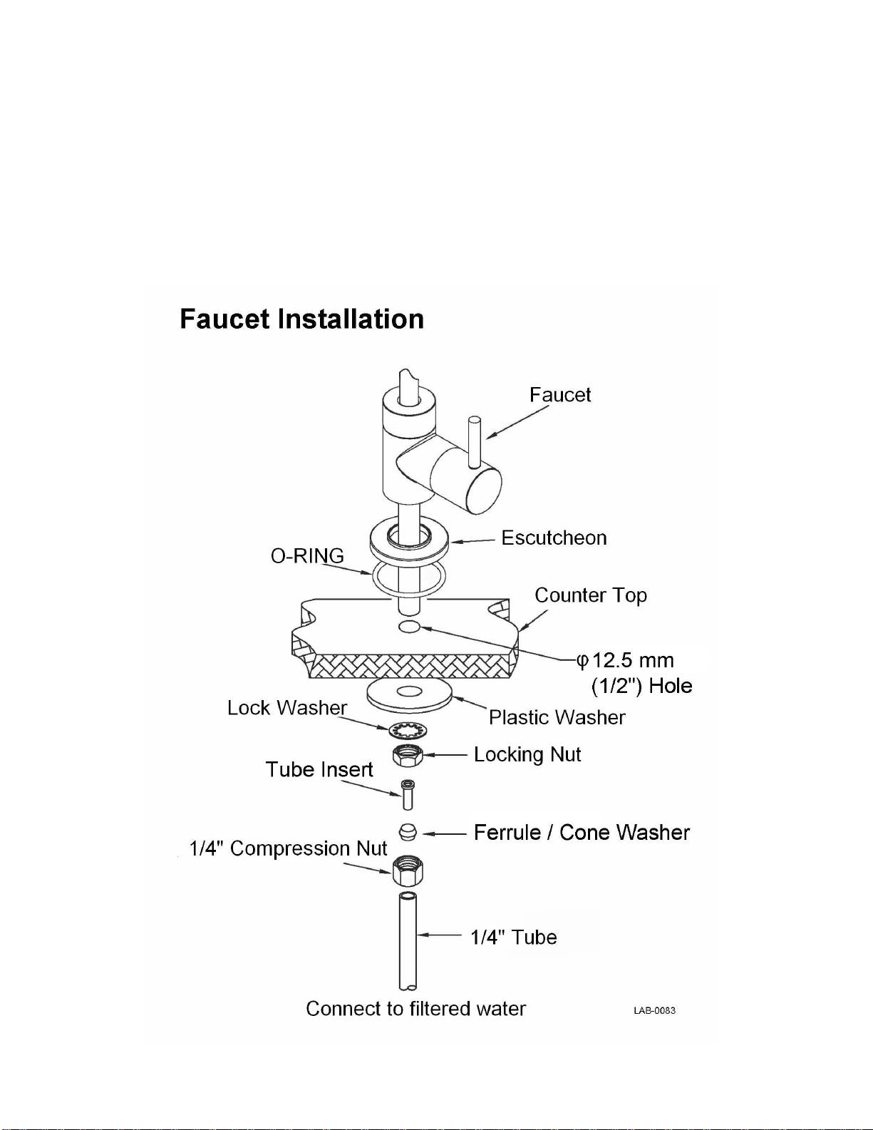
Step 4 –Faucet Installation .................................................................................................................................. 7
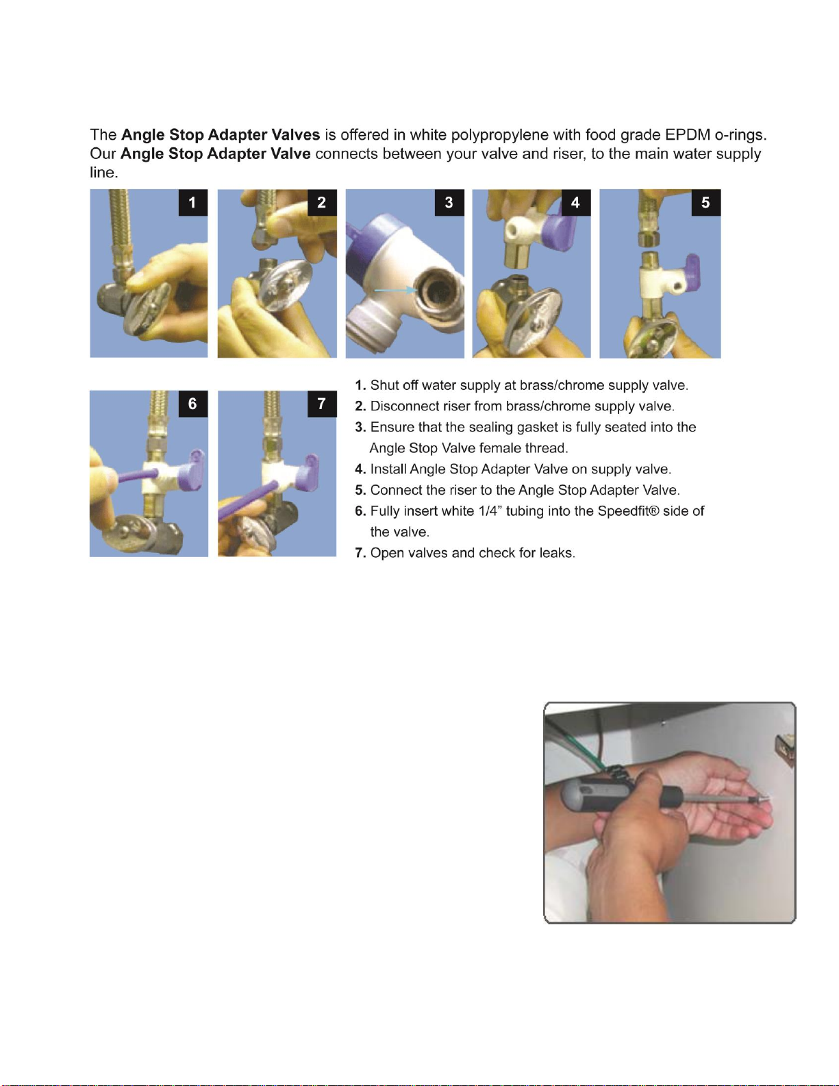
Step 5 –Water Valve (Angle-Valve) Installation .................................................................................................. 8
Step 6 –MINERALPRO Module Mounting .............................................................................................................. 8
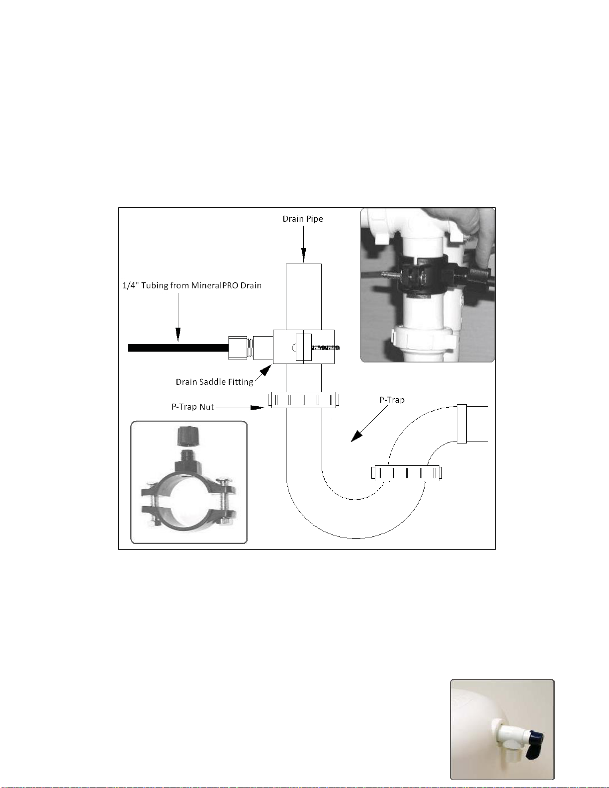
Step 7 –Drain Saddle Installation......................................................................................................................... 8
Step 8 –Tank Valve Installation............................................................................................................................ 9
Steps 9 through 13 (Tube Connections)............................................................................................................. 10
Quick Reference Tube Connections ............................................................................................................. 10
How to Use the Quick Connect Fittings on the RO Module......................................................................... 10
Step 9 –White ¼ " Tube Connection (Tank <---> MINERALPRO).......................................................................... 10
Step 10 –White ¼" Tube Connection (Angle-Valve <---> MINERALPRO)............................................................. 10
Step 11 –White ¼" Tube Connection (Faucet <---> MINERALPRO) ..................................................................... 11
Step 12 –Red ¼" Tube Connection (MINERAL PRO <---> Drain Saddle) .............................................................. 11
Step 13 –Install Cartridges................................................................................................................................. 12
Step 14 –Start-Up Instructions .......................................................................................................................... 12
Maintenance Instructions................................................................................................................................... 13
Cartridge Replacement Instructions............................................................................................................ 13
Cartridge Replacement Schedule................................................................................................................. 14
Annual Maintenance ................................................................................................................................... 14
Storage Tank Sanitization ............................................................................................................................................. 14
Tank Air Pressure .......................................................................................................................................................... 14
Procedure for Extended Non-Use (2 months or longer) .............................................................................................. 16
Manifold Assembly - Back View Diagram.......................................................................................................17
Troubleshooting ................................................................................................................................................. 17
Service Record..................................................................................................................................................... 19
Limited Warranty................................................................................................................................................ 20
NOTE: PLEASE FOLLOW THESE INSTRUCTIONS FOR FAUCET INSTALL< NOT INSTRUCTIONS ON FAUCET BOX

- 4 -
Operational Parameters:
Operating Temperatures:
Maximum 100°F (37.8°C)
Minimum 40°F (4.4°C)
Operating Pressure:
Maximum 85 psi (6.0 kg/cm2)
Minimum 40 psi (2.80 kg/cm2)
pH Parameters:
Maximum 11
Minimum 2
Iron:
Maximum 0.2 ppm
TDS (Total Dissolved Solids)
< 1800 ppm
Turbidity
< 5 NTU
Hardness: Recommended hardness should not exceed 10 grains per gallon, or 170 ppm. The system will
operate with hardness over 10 grains but the membrane life may be shortened. (Addition of a water
softener may lengthen the membrane life.)
Note: The operating pressure in your home should be tested over a 24 hour period to attain the maximum
pressure. If incoming pressure is above 85 psi a pressure regulator is recommended and if over 100 psi
then a pressure regulator is required.
Contents of MINERALPRO
1 Plastic Storage Tank
1 MINERALPRO System
1 Parts Bag
1 Manual and Warranty
1 Faucet (chrome or brushed nickel)
4 Filter Cartridges
If any of the items are missing
please contact your dealer.
*NOTE: Extra parts are included in the parts bag for optional installation types.
Tools Recommended For Installation
Tube cutters
Robertson screw driver
Variable speed electric drill
Adjustable Wrench
Plumbers putty
Lubricating oil
¼" Drill bit for drilling plastic pipe
½" Drill bit for drilling sink
Stainless Steel Sink Type (If drilling hole is required)
½" Carbide tipped hole-cutter drill bit for stainless steel
Hole punch or large nail
Hammer
Porcelain, Enamel, Ceramic on Metal or Cast Iron Sink Type (If drilling hole is required)
½" Bi-metal hole saw drill bit
¼ " Carbide drill bit
Masking tape

- 5 -
Step 1 –Determine Location for the Faucet
Note: Some sinks are predrilled or may have knockouts with 1 ½" or 1 ¼" diameter holes that can be
used for your RO faucet.
Determine the desired location for the faucet on your sink and check below the sink and countertop to
ensure clearance of any obstructions.
If the sink has a sprayer or soap dispenser, it may be disconnected for faucet installation. A pipe cap or plug
may be necessary to seal the sprayer connection.
To make a faucet hole (if sprayer hole or a secondary hole is not used) inspect under the sink area to make
sure the drill does not interfere with anything below. The faucet should be positioned so it empties into the
sink and the spout swivels freely for convenience.
If the sink has a hole that can accommodate the RO faucet, no drilling is required. Proceed with step 4 –
Mounting the Faucet.
For stainless steel sinks please see step 2. For Porcelain sinks please see step 3. For other sink types and
under-counter mountings please contact your dealer. If no locations are possible, please contact your
dealer about other faucet options.
Step 2 –Drill a Hole for the Faucet in a Stainless Steel Sink
Note: A variable speed drill with a ½" drill bit or a carbide tipped drill bit is required to drill the hole.
Lubricant such as dish soap is required to keep the drill bit cool.
Note: The use of eye protection is recommended.
2(a) - Make a dimple in the sink in the center of the hole. Use a hole-punch or equivalent sized nail and a
hammer to create this small dent. Alternatively drill a small pilot hole using a metal bit (such as
1/16" up to 1/8").
2(b) - Tape. To prevent the drill from “walking” as you drill, place a strip of masking tape over the dimple.
This keeps your drill on target (unless you’ve pre-drilled a small pilot hole as above).
2(c) - Lubricate. Form shallow putty around the hole area and fill with enough lubricant to lubricate drill
bit. Add more lubrication as needed.
2(d) - Drill. Make sure to wear your safety goggles. Use a carbide tipped metal hole cutter with a variable
speed drill. It is very important that you drill at a slow speed (i.e., 180 rpm). Push carefully at first
until the pilot bit has penetrated the stainless steel sink. The drill bit or sink can be easily damaged if
care is not taken. Once the carbide teeth are touching the surface of the sink push down harder and
maintain the slow speed. Make sure to lubricate often. Only drill through the stainless steel for now.
2(e) - Remove tape and clean-up. Be very careful with the metal chips and the edge of the hole, they are
extremely sharp.

- 6 -
2(f) - Drill countertop if necessary. Inspect hole and determine if more drilling is required to drill through
any countertop that may be present under the sink. Use the appropriate drill bit suitable for counter
material. Clean-up when drilling is completed.
Step 3 –Drill a Hole for the Faucet in a Porcelain, Enamel, Ceramic on Metal or
Cast Iron
Notes: Precautions must be taken to penetrate the porcelain through to the metal base and prevent it
from chipping or scratching.
The use of eye protection is recommended.
3(a) - Mark the center for the 5/16th hole. Place masking tape over location
where hole is to be drilled, and mark the center of the hole on the tape.
3(b) - Lubricate. Form shallow putty around the hole area and fill with enough
lubricating oil or liquid soap to lubricate drill bit. Add more lubrication as
needed.
3(c) - Drill pilot hole. Make sure to wear your safety goggles. Using a variable
speed drill on the slowest speed, carefully drill 5/16th pilot hole through
all layers. (If drill bit gets hot it may cause porcelain to crack or chip, add
more lubricating oil or liquid soap as needed.)
3(d) - Drill faucet hole. Make sure to wear your safety goggles. Using a ½" drill
bit, proceed to drill the large hole. Keep drill speed on the slowest speed
and use lubricating oil or liquid soap to the keep the hole saw cool during
cutting.
3(e) - Remove tape and cleanup. Carefully remove all sharp edges and clean-
up all lubrication. Make sure surroundings of the sink are cooled from
drilling before mounting the faucet to the sink after drilling.
3(f) - Drill countertop if necessary. Inspect hole and determine if more
drilling is required to drill through any countertop that may be present
under the sink. Use the appropriate drill bit suitable for counter material.
Clean up when drilling completed.

- 7 -
Step 4 –Faucet Installation
4(a) - Place the escutcheon chrome plate and the black rubber washer on the faucet shank
(parts found in faucet box).
4(b) - Insert the faucet shank through the hole in the sink and let it rest on the sink top.
4(c) - From the underside of the sink slide on the location washer, lock washer and locking nut onto
the shank. Check orientation of faucet then tighten locking nut securely.

- 8 -
Step 5 –Water Angle Valve Installation
Caution: Water supply line to the system MUST be from the cold water supply line only. Hot water will
severely damage your system.
Step 6 –MINERALPRO Module Mounting
6(a) - Determine best location for the RO module to be
mounted to allow for future system maintenance. The
parts bag has 2 self-tapping screws. Using a Robertson
screwdriver, screw them into the cabinet wall 7 7/8"
apart and 16" from the bottom of the cabinet.
Note: Cut the black tape holding tubes together. Do not cut
zip straps as this keeps tubing neat and tidy.Do not cut
any RO system tubes at this time.
Step 7 –Drain Saddle Installation
Note: Drain Saddle fits standard 1 ¼" –1 ½" drain pipes

- 9 -
Caution: If you have a garbage disposal, do not install the drain line near it. Installation of the drain
line must be either above the disposal, or if a second sink drain is available, install it above
the cross bar on the second sink. Installation of the drain line near a garbage disposal may
cause the drain line to plug.
7(a) - Gather the pieces of the drain saddle:
1 - Black compression nut
1 - Semicircle bracket with opening
1 - Semicircle bracket
2 - Screws
2 - Nuts for screws
7(b) - Drill a ¼" hole through the drain pipe at least 1 ½" above the top nut of the P-trap to allow for
the removal of the P-trap if necessary. Assemble the drain saddle around the drain pipe. Position
the drain saddle over the drilled hole in pipe. Insert screw driver into the opening of the drain
saddle and align with drilled hole in drain pipe. Using a Philips screw driver tighten screws evenly
and securely on both sides of the drain saddle. Attach black compression nut, but do not tighten
at this time. The black tubing will be installed later. Caution: Do not over tighten the screws, it
may crack the drain saddle.
Step 8 –Tank Valve Installation
8(a) - Make sure the O-Ring is located at the bottom of the recess for
the tank connection.

- 10 -
8(b) - Thread the plastic valve onto the tank fitting. Do not over tighten
or the valve could crack.
Steps 9 through 12 (Tube Connections)
Quick Reference Tube Connections
Tube Color
Tube Size
Tube Connection
White
¼ "
Angle-Valve to MINERALPRO (IN)
White
¼ "
Tank to MINERALPRO
White
¼ "
Faucet to MINERALPRO
Red
¼ "
MINERALPRO TO ¼” drain saddle
Note: leave some extra tube on runs and avoid kinking tubing
How to Use the Quick Connect Fittings on the RO Module
Cut tube square with tube cutter. Do not use hacksaw or
any other saw. O-ring must be free from burrs and sharp
edges.
Push the tube into the fitting, to the pipe stop. The
collet (gripper) holds the tube firmly in position and the
'O' Ring provides a permanent leak proof seal.
Pull on the tube to check that it is secure. It is a good
practice to test the system prior to leaving site and /or
before use.
To disconnect, ensure the system is depressurized
before removing the tube. Push in collet squarely
against face of fitting. With the collet held in this
position, the tube can be removed. The fitting can then
be reused.
Step 9 –White ¼ " Tube Connection (Tank <---> MINERALPRO)
9(a) - Position tank in desired location. Stand it upright or lay it on its side.
9(b) - Locate the ¼ " white tube marked 'Tank' and run up to the tank, cut tube if needed and insert
tube into quick fit tank valve.

- 11 -
Step 10 –White ¼" Tube Connection (Angle-Valve <---> MINERALPRO)
10(a) - Locate ¼ " white tube labeled "in" from MINERALPRO.
10(b) - Run to side outlet on angle valve. Cut if needed and insert into valve outlet.
Step 11 –White ¼ "Tube Connection (Faucet <---> MINERALPRO)
11(a) - Locate ¼ " white tubing labeled "faucet" and run up to the base of the faucet. Cut if necessary
and install the ¼ " white tubing into faucet as shown in the "FAUCET INSTALLATION" diagram.
Slide ¼ " compression nut over end of tube, slide cone washer (ferrule) over pipe, insert tube
insert into end of tubing, then slide tubing into end of faucet and tighten up the ¼ "
compression nut to secure in place.
Step 12 –Red ¼" Tube Connection (MINERALPRO <---> Drain Saddle)
12(a) - Locate the ¼" red tube labeled "drain" from MINERALPRO.
12(b) - Run ¼" red tubing over to the drain saddle and measure length required
to connect into the drain saddle. Keep tube run as direct as possible, with

- 12 -
no kinks and cut as needed. /remove nut from saddle fitting, place nut
over tubing and push tubing with nut attached into the connection of the
saddle drain fitting. Hand tighten as needed.
Step 13 –Install Cartridges
13(a) - Identify each cartridge and the proper location on the system by
matching the colors and description.
Stage 1 –Sediment Filter (Cleanse)
Stage 2 –Pre-Carbon Filter (Purify)
Stage 3 –RO Membrane (Detoxify)
Stages 4/5 –Mineral/Carbon Filter (Mineralize)
13(b) - Write the date of installation on each cartridge and insert each cartridge with a ¼ turn in the
clockwise direction. The cartridge is installed properly when the label is facing toward the front
of the unit. Record the installation information on the system service record.
Note: The cartridge heads swivel up and down for easy access. See Cartridge Replacement
Instructions on page 14 for further information.
Step 14 –Start-Up Instructions
14(a) - Turn on the incoming cold water at the angle stop valve. Open the valve on the Angle-Valve by
turning counter clockwise. Check the system for leaks and tighten any fitting as necessary.
(Check frequently over the next 24 hours to ensure no leaks are present).
Note: Leave tank valve off on start-up to pressurize the system and test for leaks. Flush carbon
fines from the cartridges.
14(b) - If system is connected to an ice maker, turn the ice maker off (or do not allow water to flow to
the ice maker) until Step 14(e) “flushing” is complete and the tank has been allowed to
completely fill. Connection from the RO to the ice maker system should have an in-line valve
installed before the ice maker so it can easily be closed to prevent water flowing to the ice
maker during start up and periodic maintenance. Your RO tank must be allowed to fill up in
order for the ice maker system to work properly. (If you are installing an ice maker kit from
MineralPRO, tee off of the white line between MINERALPRO system and faucet).

- 13 -
14(c) - Open the RO faucet and leave it open until water begins to trickle out (it will come out slowly
and may take several minutes before any water comes out).
14(d) - After water trickles out of the faucet, close the faucet so the tank will fill with water. The tank
will take 4 to 8 hours to fill completely depending on the production capability of the
membrane, local water temperature and pressure.
14(e) - After the Tank has filled, open the faucet to flush the tank completely to remove carbon
particles from final filter. Repeat this step two more times. The fourth tank can be used for
drinking. Note: The flushing of the tank 3 times is only necessary during initial installation.
This should take about a day to complete.
NOTE: This reverse osmosis system contains replaceable components critical to the efficiency of
the system. Replacement of the reverse osmosis component should be with one of
identical specifications, as defined by the manufacturer, to assure the same efficiency
and contaminant reduction performance. Periodic inspection and following proper
system maintenance is critical for continued performance.
Maintenance Instructions
Cartridge Replacement Instructions
Cartridge replacement is made easy with the MineralPRO’s Quick Change system. The cartridge
heads contain built in check valves and shutoff valves so that the cartridges can be changed without
shutting off the water supply or the storage tank. The cartridge head is also hinged to allow easy
access to the cartridges.
The following steps should be followed to change the cartridges.
Note: A small amount of water may be released when changing cartridges.
Step 1 Grasp the old cartridge and pull it towards you.
Step 2 Rotate the old cartridge ¼ turn counter clockwise.
Step 3 Remove the old cartridge and dispose of it.
Step 4 Remove the protective cap from the new cartridge.
Step 5 Write the date of installation on the new filter cartridge.
Step 6 Orient the new cartridge with the label facing to the left (9 o’clock position)
Step 7 Push the new cartridge into the head and rotate it clockwise ¼ turn.
Step 8 Return new cartridge to the vertical position.
Step 9 Wipe up any spilled water.
Step 10 Open the faucet for a few minutes to completely empty and flush the tank of carbon
particles from final filter. Close the faucet once water runs clear. You may be required to
flush tank twice to remove any carbon fibers.

- 14 -
Step 11 Close the faucet and allow tank to fill up.
Step 12 Record the date and information of the cartridge change on the system service record.
Cartridge Replacement Schedule
Stage
Cartridge Name
Replacement Schedule
1
Sediment Filter
6 months
2
Pre-Carbon Filter
6 months
3
RO Membrane
2 years
4/5
Mineral/Carbon Filter
1 year
Annual Maintenance
Storage Tank Sanitization
1. Turn off the supply valve to the system, open the RO faucet and drain tank.
2. Remove the tube from the rear of the RO manifold marked "Tank" and shake the water out of the
tube. Please refer to the diagram below.
Push in collet squarely against face of fitting. With the collet held in this position, the tube
can be removed. The fitting can then be re-used.

- 15 -
TO DISCONNECT
in collet and remove tube
To disconnect, ensure the system is depressurized, push the collet square against the fitting. With the
collet held in this position the tube can be removed.
3. Fill a small glass or cup with water, add a few spoonfuls of bleach to the water and mix well.
4. Using a plastic syringe, draw the water/bleach mixture into the syringe, hold the tube up and
squirt mixture into the tube going into the tank. Repeat 4 or 5 times, holding the tube up to
fill with bleach solution.
5. Once the tube is full, reconnect the tube to the RO manifold, turn supply valve on and allow
tank to fill up with water (this may take 1-2 hours).
6. Leave tank full for 2 hours to sanitize completely.
7. After 2 hours, open the RO faucet and drain the tank completely. Close the faucet and let
tank fill with water again and drain tank once again. The tank is now sanitized and the
bleach is effectively removed. Proceed with checking the air pressure.

- 16 -
Tank Air Pressure
The storage tank air pressure should be checked yearly to ensure proper operation.
Step 1 Turn off the incoming water supply at the Angle-Valve.
Step 2 Open the faucet, allow the tank to empty, and then close the faucet.
Step 3 Check the pressure in the tank using a tire pressure gauge on the air valve.
Step 4 The tank pressure should be between 5-7 psi. Use a bicycle pump to add air if necessary.
Step 5 Turn on the water supply at the Angle valve.
Note: Tank comes pre-charged from factory but should be tested annually after the first year
of service.
Procedure for Extended Non-Use (2 months or longer)
If the system will not be used for an extended period (more than 2 months) perform the following:
Step 1 Turn off the incoming water supply at the Angle-Valve.
Step 2 Open the faucet, allow the tank to empty, and then close the faucet.
Step 3 Remove and discard the sediment filter, pre-carbon filter, and post carbon filter
cartridges.
Step 4 Remove the RO membrane cartridge. Place it in a zip lock bag and store in rerigerator.
Step 5 To begin using the unit again, follow the startup and tank sanitization procedures.

- 17 -

- 18 -
Troubleshooting
Problem
Cause
Solution
1. Low/Slow Production
Low water pressure
Assure a minimum of 40 psi incoming water pressure. MineralPRO
sells a booster pump if home water pressure is low. Make sure
water supply is turned on and Adapta-Valve is all the way open.
Crimps in tubing
Check tubing and straighten or replace as necessary.
Clogged pre-filters
Replace pre-filters.
Fouled membrane
Replace membrane and clean flow restrictor.
Tank valve closed
Open valve on storage tank
2. Colored Water
Air in System
Air in the system is a normal occurrence with initial start
up of the RO system. This milky look will disappear
during normal use within 1-2 weeks. If condition reoccurs
after filter change, drain tank 1 to 2 times.
3. Water constantly
running/unit will not
shut off
Low water pressure
See #1 Above
Fouled membrane
Replace membrane.
High water pressure
Check incoming water pressure to make sure it does not exceed
100psi. A pressure relief valve or pressure regulator valve may be
necessary.
4. Noise from faucet or
drain
Air gap faucet
Inherent sound with air-gap faucets.
Location of drain saddle
See diagram for proper location of drain saddle.
Higher capacity membrane
Normal with high capacity membrane.
High water pressure
Check incoming water pressure to make sure it does not exceed
100psi. A pressure relief valve or pressure regulator valve may be
necessary.
5. Faucet leaks from the
air gap feature
Crimp or loop in drain line
Straighten red 1/4" drain tube. Cut off any excess tubing.
Drain tube clogged/restricted
Caused from dishwasher or garbage disposal. Disconnect the 1/4"
red tube at the drain, clean the 1/4" red tube out with a wire, and
then reconnect.
6. Small amount of water
in storage tank
System is just starting up
Normally it takes 4-10 hours to fill tank. Note: Low pressure and/or
temperature can drastically reduce production rate.
Low water pressure
See #1 Above
Too much air in tank
Add air if below 5 psi and bleed if above 5 psi. Check only when tank
is empty of water. See page 15.
7. Water leaks from the
filter housing
Not properly tightened.
Tighten the cartridge.
Missed or kinked O-ring
Turn off water supply. Release the water pressure, remove the filter
cartridge and replace the O-ring. Make sure the O-ring is seated
correctly in the filter cartridge before reinstalling the filter
cartridge.

- 19 -
Service Record
Date of Install: ________________ Installed by: _________________ Serial No. ______________________
Date
1st Stage
Sediment
(6 months)
2nd Stage
Pre-Carbon
(6 months)
3rd Stage
RO Membrane
(2 years)
4th Stage
Carbon/Mineral
(1 year)
NOTES:
Table of contents
Popular Water Dispenser manuals by other brands

Magic mill
Magic mill MUR25 owner's manual

Elkay
Elkay Space-ette FHD70052EJO Series Installation, care & use manual

Culligan
Culligan Super S Installation and operating insctructions

Trixie
Trixie Duo Stream instruction manual

Elkay
Elkay VRCDWS A Series Installation, care & use manual

Follett
Follett 7CI100A Installation, operation and service manual

Aquasana
Aquasana OptimH2O AQ-RO3-R owner's manual

InSinkErator
InSinkErator H990 Installation, care & use guide

Vertex
Vertex PureWaterCooler PWC-1800 Service manual

Fetco
Fetco HWB-10 Installation

HANDONG HYDRO
HANDONG HYDRO H2-mini instructions

Spectrum
Spectrum MixH2O-PRO Installation, service & operation manual