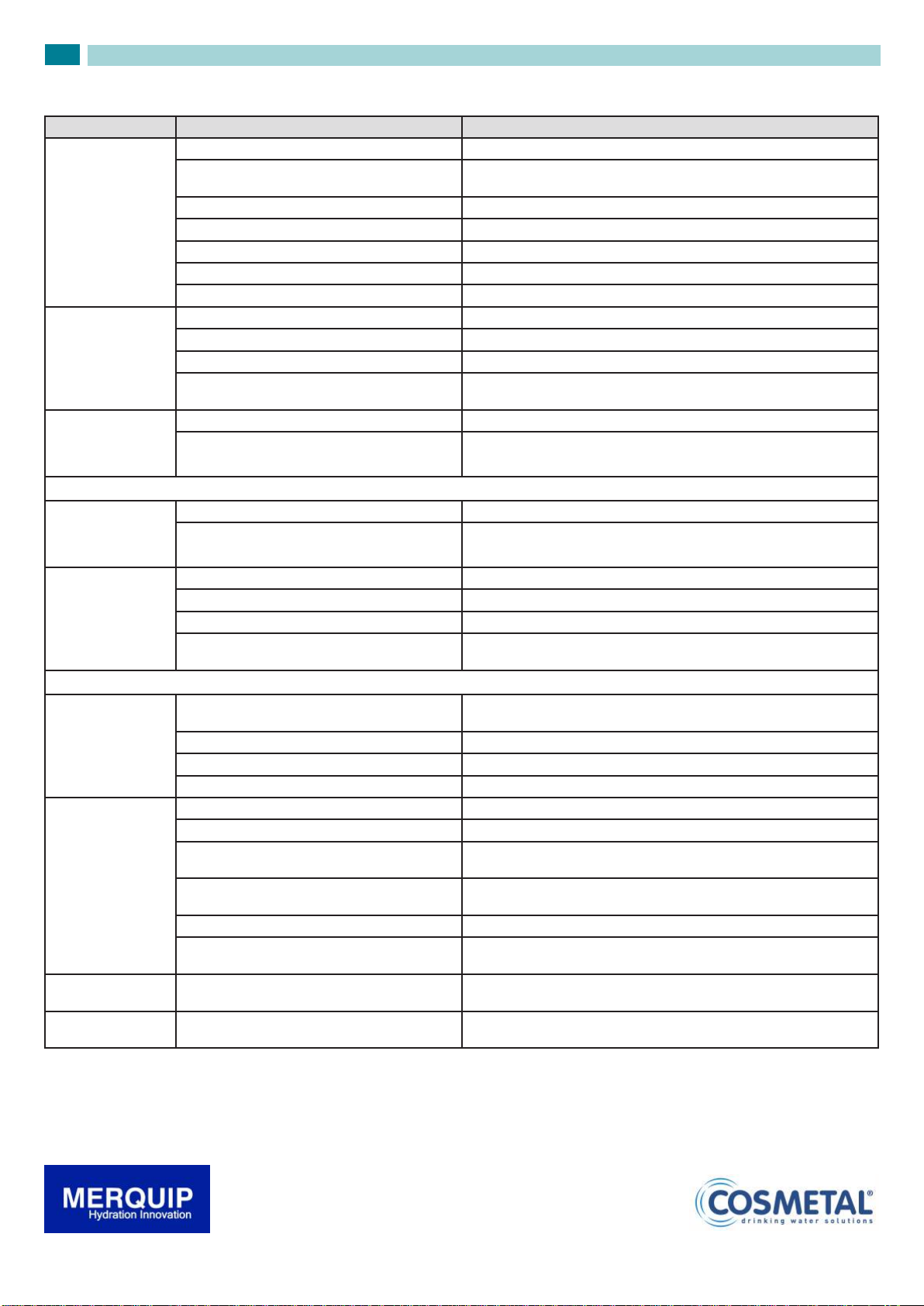
MERQUIP NIAGARA Manual

I
GB
D
F
E
Installation, use and maintenance handbook
Rel. 150905
NIAGARA
COD: 5561397
Rev.0:0210
1

MANUFACTURER
Mod. ..................
..........V ..........Hz ..........W ..........A
Freon R134a kg............. Classe T
MADE IN ITALY
WATER COOLERS
1
Model
2
Supply voltage
3
Quantity of cooling gas
4
Class
5
Total absorption
6
Frequency
7
Serial number
8
Construction year-month
APPLIANCE DATA PLATE
1
25
000100 0102
7 8
6
34
CONFORMANCE
STATEMENT
This appliance has been manu-
factured with suitable materials
for use with drinking water. The
device conforms to L.D.108 dated
25.01.1992. The appliance has
been approved by the WRAS
(WATER REGULATION ADVISO-
RY SCHEME).
.
This product was designed,
made and put on the market
respecting the following con-
formities:
• Following EC requirements
safety objectives of the
“Low Voltage” 2006/95/
CEE;
• protection requisites of
“EMC” 2004/108/ CEE
• Certied by NEMKO .
• Keep this book for later use.
• When you have removed the packaging, make sure that the appliance is not da-
maged. Any damage must be reported to your carrier within 24 hours.
In order to use your appliance to its best, we advise reading these
instructions carefully as they contain useful information.
• Make sure that installation and electrical wiring are carried out by a qualied
technician according to the manufacturer’s instructions and to the local norms in
force. The electrical system must be equipped with an effective earth according
to the law (46/90).
1.2 GENERAL PRECAUTIONS AND SUGGESTIONS
• Do not pull on the supply cable in order to remove the plug from the socket.
• When the appliance has been installed, make sure it is not resting on the mains
supply cable.
1.1 WARNINGS
1 BEFORE USING THE APPLIANCE
GB
Before carrying out any maintenance or cleaning operation,
remove the plug from the mains socket.
The data and characteristics indicated in this manual do not
bind the manufacturer, who reserves the right to make all the
modifications deemed necessary, without having to give prior
notice or replacement.
If the machine has been put down or turned upside down, wait
for at least 8 hours before putting it into operation
2

• Place of installation
• Do not place the machine near inammable solvents such as alcohol or
diluents.
• Do not install the machine in excessively damp and dusty places, exposed
to direct sunlight, outdoors or near to heat sources.
Machine installation in these places could cause res or electric shocks.
• The appliance is not suitable for outdoor use and it is also not recommen-
ded to install it in very damp rooms.
• For safe and correct functioning the appliance must be placed at
• Electric power supply
• Do not connect or disconnect the machine from the socket with wet hands.
• Insert the plug into the wall socket rmly.
• Do not damage, modify, stretch, bend or twist the power cable.
Do not place heavy objects on the power cable.
• Do not connect the machine to a socket to which other equipment is
connected (extensions, 2 or 3 plug adaptors, etc.)
• Do not use the machine if the power cable is tied or knotted.
• If smoke, unusual smells or strange noises are found coming from the
machine, disconnect it immediately from the socket and contact the local
retailer or technical service assistance.
Use of the machine in these conditions could cause res or electric
shocks.
• Periodically disconnect the machine from the socket and clean the plug
and socket with a dry cloth.
If the machine is connected in a place exposed to dust, smoke or high
humidity, the dust accumulated on the plug will absorb humidity and this
could alter the insulation and trigger a re.
• The appliance must not be installed where water jets can be generated.
• Do not spray water on the device; this could cause electric shocks or
res.
• Use a damp cloth to clean the machine. Do not use inammable solvents
such as alcohol, benzene or diluents. If inflammable substances come in
contact with the electrical components inside the machine, they can cause
res or electric shocks.
Never use water jets to clean the machine.
• Before cleaning the machine, switch it off and disconnect it from the socket.
Not being switched off or accidental switching on during cleaning could
cause injuries to persons or damages to the machine.
1 BEFORE USING THE APPLIANCE
GB
Failure to comply with any of these safety regulations could
cause res, electric shocks or damage the machine
3

NI1404-050
1 1.1
R
F
S
B
R
C
2.1 ADVICE ON HOW TO PROTECT THE ENVIRONMENT
Packaging: Packaging material is 100% recyclable.
For its disposal follow your local regulations.
The packaging material (plastic bags, polystyrene parts etc.) must be kept
out of children’s reach as it could be dangerous.
The symbol on the product, or on the documents accompanying the
product, indicates that this appliance may not be treated as household
waste. Instead it shall be handed over to the applicable collection point
for the recycling of electrical and electronic equipment.
Disposal must be carried out in accordance with local environmental regulations
for waste disposal.For more detailed information about treatment, recovery and
recycling of this product, please contact your local city ofce, your household
waste disposal service or the shop where you purchased the product.
Information: This appliance does not contain CFCs (the cooling circuit
contains a gas that is not harmful to the ozone layer).
For further details, please refer to the serial data plate on the appliance.
Produkt: This appliance is marked according to the European directive
2002/96/EC on Waste Electrical and Electronic Equipment (WEEE).By
Ensuring this product is disposed of correctly, you will help prevent potential
negative consequences for the environment and human health, which could
otherwise be caused by inappropriate waste handling of this product.
• Place the appliance in its installation site (chap. 5 - INSTALLATION).
• Cut straps R and remove carton C, polystyrene F and external plastic bag S.
• Do away with plastic bags S and polystyrene F immediately as they are a danger
for children.
• Once the appliance is free from its packaging, remove the base B.
GB
2 REMOVAL OF PACKAGING
Attention: when moving the TOP models the distribution head
must not be used to hoist the machine.
The hoisting of the machine must happen from the bottom and
be carried out by at least two people (fig.2)
4

2
1
2 3
These water coolers were designed to provide large quantities of still and
carbonated cold water.
They are easy to use and manufactured using top quality materials, offering
the utmost hygiene and ease of maintenance; a UV safety system, available
as an optional in the ground and counter-top models (TOP). It protects the
water distribution area from bacteria (patented system).
They should always be connected to a mains drinking water supply and can
be tted with special ltering kits.
They can be used in various settings, ranging from cafés, restaurants,
canteens, hospitals, public places, ofces and domestic environments; they
should always be installed indoors and in the environmental conditions
described under the “technical features” heading.
They are equipped with an internal cooling system, capable of supplying
water cooled to 3 ÷ 10°C.
They use a direct cooling system (ice bank)
The following models are available:
- Ground (1)
- Undercounter (2)
- Countertop (3)
Some models can also provide carbonated water (WG versions), in which
case they need to be connected to a CO2cylinder.
The ground 1 and countertop 3 models have, as standard, a solenoid valve
with safety function (anti-flooding).
3 DESCRIPTION OF THE APPLIANCE
GB
5

3
GENERAL VIEW
4
3
11
15
16
17 8
10
12
13
14
7
2
2
5
6.1
A
C
B
6.2 6.3
9
66.4 6.5
1
SL
1) Structure
2) Front panel
3) Panel fastening
4) Tray grille
5) Column
6) Top
6.1) Cold water button
6.2) Button for water at room temperature
6.3) Sparkling water button (WG models)
6.4) Network voltage warning light
6.5) No water warning light (WG models)
7) Load ice compartment (ø 8mm)
8) Data plates
9) Distribution nozzle positioned in a protected area
10) Mains water inlet ø 8mm (or 3/4 M )
11) Power supply cable
12) Drain water (ø 24mm) and overflow ice compartment
13) Removable panel for compressor maintenance
14) Adjustable levelling feet
15) Main ON/OFF switch
16) Cold water thermostat
17) Removable panel of the distribution column
A) Continuous dispensing
B) OFF
C) Pulsating dispensing
3.1 FREE STANDING MODELS
GB
6

4
5IN
TOP
CARICO ACQUA
FILL ICE BANK
6.1 6.3
6.2
6.4 6.5
2
14
3
5
7
7
15
15
5
3
2
1
1
13
6
10
8
9
11
12
13
1) Cold water thermostat
2) Electrical power supply socket
3) Main switch
5) Mains water inlet ø 8mm or 3/4 M
6) Top
6.1) Cold water button
6.2) Button for water at room temperature
6.3) Sparkling water button (WG models)
6.4) Network voltage warning light
6.5) No water warning light (WG models)
7) Load ice compartment ø 8mm
13) Ice compartment drain too full
15) CO2inlet ø 8mm (WG models)
GB
3.2 COUNTERTOP MODELS (TOP) 3.3 UNDERCOUNTER MODELS (IN)
1) Cold water thermostat
2) Electrical power supply socket
3) Main switch
5) Mains water inlet ø 8mm or 3/8 F
7) Load ice compartment ø 8mm
8) Cold water outlet ø 8mm (OUT WATER)
9) Outlet for water at room temperature ø 8mm (OUT AMBIENT)
10) Sparkling water outlet ø 8mm (WG models) (OUT SODA)
11) Water re-circulation delivery
12) Water re-circulation return
13) Ice compartment drain overflow
14)
Removable panel for compressor maintenance
15) CO2inlet ø 8mm (WG models)
7

6
Dimensions
(mm)
NIAGARA IN
NIAGARA SL
NIAGARA TOP
4
TECHNICAL CHARACTERISTICS
GB
AB
H
C
D
A
B
H
311
495
985
A B
338
H
818
IN 65
IN 65 WG
IN
120
IN
120 WG
T
IN
180
IN
180 WG
A 420 480 530
B 350 350 350
H 500 500 500
TOP 65
TOP 65 WG
TOP 120
TOP 120 WG
TOP 180
TOP 180 WG
A 370 370 370
B 422 482 532
C 495 495 495
D 345 345 345
H 510 510 510
65 SL
120 SL
180 SL
65 SLWG
120 SLWG
180 SLWG
A 405 560
B 480 480
H 1480 1480
8

4.1
CONDITIONS
OF
THE
SURROUNDINGS
ROOM
TEMPERATURE:
Min
10°C
Max
45°C
Lt/h
Water production
usg/h
°C
Water outlet temperature
°F
Continuous cold water production
Lt
Usg
Kg
Ice bank
Ibs
Cooling system
Compressor
HP
Rated input
Watt
Supply
Volt/Hz
Carbonating system
kg
Net weight
Ibs
Charge
g
A-weighted sound pressure level
65
17,2
40
10,6
4,5
10
1/6
300
-
33
73
160
< 70
dB
65
WG
65 120 120
WG
65
17,2
40
10,6
4,5
10
1/6
500
41
90
160
< 70
dB
120
31,7
70
18,5
6,5
14,3
1/3
500
-
39
86
250
< 70
dB
120
31,7
70
18,5
6,5
14,3
1/3
800
49
108
250
< 70
dB
6.1
65 65
WG 120 65 65
WG 120
65
17,2
40
10,6
4,5
10
1/6
300
-
29
63,9
160
< 70
dB
65
17,2
40
10,6
4,5
10
1/6
500
37
81,5
160
< 70
dB
120
31,7
70
18,5
6,5
14,3
1/3
500
-
37
81,5
250
< 70
dB
65
17,2
40
10,6
4,5
10
1/6
300
-
32
71
160
< 70
dB
65
17,2
40
10,6
4,5
10
1/6
500
40
88
160
< 70
dB
120
31,7
70
18,5
6,5
14,3
1/3
500
-
40
88
250
< 70
dB
180
47,5
100
26,4
11,5
25,3
1/3
500
-
52
115
390
< 70
dB
180
WG
120
WG
120
31,7
70
18,5
6,5
14,3
1/3
800
48
106
250
< 70
dB
180
WG
180
47,5
100
26,4
11,5
25,3
1/3
500
-
51
112
390
< 70
dB
180
47,5
100
26,4
11,5
25,3
1/3
800
60
132
390
< 70
dB
3 ÷ 10
38 ÷50
120
WG
120
31,7
70
18,5
6,5
14,3
1/3
800
45
99,1
250
< 70
dB
180 180
WG
180
47,5
100
26,4
11,5
25,3
1/3
500
-
43
94,7
390
< 70
dB
180
47,5
100
26,4
11,5
25,3
1/3
800
51
112,3
390
< 70
dB
180
47,5
100
26,4
11,5
25,3
1/3
800
60
132
390
< 70
dB
Banco di ghiaccio / Ice bank / Eisbank / Banc de glace / Banco de hielo
180 180
230 / 1 / 50 Hz
NIAGARA SL NIAGARA IN NIAGARA TOP
FREON
R134A
9

7
7.1
7.2
NI1404-F01
2
1
S
S
S
S
5.1 POSITIONING THE APPLIANCE
Position the appliance in the point of installation, away from sources of heat and
direct sunlight.
The appliance is not suitable for outdoor use and it is also not recommended to
install it in very damp rooms.
- Adjust the feet in ground models (1) to make the structure level (g.7).
- The appliance should be positioned in such a way as to leave approximately 10
cm of space free
S
for air to circulate freely; the condenser side must be easily
accessible for cleaning.
- Special ventilation grills/slits must be prepared in the undercounter model’s housing
compartment to favour disposal of the heat produced by the refrigerating circuit
(g.10).
We recommend creating 300x300 mm or of equivalent measure ventilation
grills
- Make sure the water cooler is resting fully on all four supporting feet.
-For safe and correct functioning the appliance must be placed at
5 INSTALLATION
GB
10

NI1404-110
89
9.1 10
NI1404-100
NI1404-090
T
A
R
P
K
• This water dispenser can be equipped with a WATER BLOCK anti-ooding
device (optional) to prevent any accidental water leaks (g.9).
Once the WATER BLOCK device has intervened, tting Kshould be
disassembled and button Ppressed to reset the device.
• If instead of being connected directly to the aqueduct the machine is
connected to an autoclave pump, then it is necessary to install above the
water supply an ANTISHOCK device to prevent “water hammers” (g.
9.1)
5.2 WATER CONNECTION TO THE MAINS
Before water connection, check that the network pressure is between 2 and
3 bar and flow more than 3.5 l/min.
• If the mains pressure is below 2 bar or the flow rate is less than 3,5 l/
min, t a device capable of increasing the mains pressure (such as an
autoclave or similar).
5 INSTALLATION
GB
During connection of the appliance to the mains water supply,
all pre-existing tubes, gaskets and joints placed between the
appliance and the water mains connection must be replaced
with new material to avoid contamination.
N.B.: the pressure is especially important for those water coolers
fitted with a carbonation device.
Attention! All models are equipped with a water pressure reducer
calibrated at 3 bar, installed on the machine on ground models and
supplied separately with other models.
11

I
0
11 12 13
NI1404-F12
NI1404-030
16
15
NI1404-180
14
16.1
7
7
13
A
T
R
1
1
T
T
• On models IN and TOP the clean water drainage pipe of the ice bank 13
(if present) must be connected to a siphoned drain. If necessary cut the
pipe to prevent narrowing or rising.
In the SL models, the clean water drainage pipe is already provided with a
siphon inside the cabinet (g. 16.1); connect said pipe to the drainage ensur-
ing it is not bent, otherwise it prevents the siphon from draining the water.
• Connection to the mains water supply is carried out with the aid of pipe
T provided (8mm diameter).
• The pipe terminal A (g. 12) (3/8”) must be connected to the mains supply
by means of a stop cock R (not provided).
• Connect the pipe T to the stop cock, making sure that the o-ring gasket
is correctly positioned onto the attachment A.
• Connect the tube T to the connection 7 (f i l l i c e b a n k ) and ll the ice tank;
once reached the right level, the exceeding water is eliminated from the
draining 13 (g. 15).
• Take off tube T from the connection 7 and connect it in the connection 1
(i n w a t e r ) exerting pressure as shown on picture 11 (IN models) or picture
14 (TOP and FLOOR models). The connection 7 (f i l l i c e b a n k ) has to be
5.3
ELECTRICITY CONNECTION
Connection to the mains electricity supply is carried out by connecting the plug to
a mains socket
(g.16).
The supply socket must be equipped with an efcient earth plate and it must be sized
for the load of the appliance (see technical characteristics).
Make sure that the mains voltage corresponds with what is specied on the data plate.
Make sure that there is an omnipolar switch above the socket with a minimum contact
break of 3 mm protected by fuses of suitable amperage for the absorption of the
appliance itself (see technical characteristics and data plate).
disconnected.
• If you need to unfasten pipe T (g. 13):
- press onto the locking ring using an ø 8mm spanner while at the same
time pulling on the pipe to extract it.
The green luminous main ON/OFF switch, allows the easy
disconnection of the appliance from the mains electricity
supply
GB
12

6
123
4
5
7
OFF
COLDER
NI1404-120
17
18
CO2
6
123
4
5
7
OFF
COLDER
FILLICEBANKIN CO2
IN WATER
18.1
T
R
N
G
B
1
12
3
3
2
6.1 CIRCUIT FILLING
• Turn on the water tap and make sure there are no leaks.
• Adjust thermostat 1in the maximum position.
• Turn on the main ON/OFF switch 3.
• Press the sparkling water button until all the remaining air is eliminated
from the circuit.
• Repeat the operation with the cold water button
6.2 CONNECTION TO THE CO2 CYLINDER (WG models)
For the production of carbonated water, you must provide a CO2cylinder
for alimentary use.
For cylinder dimensions and capacity, please refer to the “technical
characteristics” chapter.
• Extract the front panel.
• Connect the pressure reducer R to the CO2cylinder B, making sure the
gasket G is in the correct position.
• Tighten nut N and check that the pipe T (outlet) is well connected.
• Place the cylinder and reducer within the appliance, in the predisposed
housing.
• The bottle has to be xed with the special included pieces.
In counter top and under counter versions, the cylinder is
placed outside the appliance.
In the ground versions, the cylinder can be housed inside the
cabinet, as long as it falls within the maximum dimensions:
height 87 cm, diameter 17 cm.
6 STARTING
GB
Warning! If the appliance has been laid down or turned upside
down, you should wait at least 8 hours before starting it.
13

19
CO2
NI1404-130
2
CO2 cylinder charging range Lt
CO2 cylinder capacity
4 Kg (8,8 Ibs)
700
184,1
10 Kg (22 Ibs)
1600
420,8
5
6
3
2
1
4
7
6.3
SETTING UP THE SPARKLING WATER
1) CO2cylinder
2) CO2cylinder tap
3) CO2pressure regulator
4) CO2pressure adjusting screw
5) CO2outlet pipe
6) Cylinder internal pressure gauge
(shows whether there is any gas inside the cylinder)
7) Outlet CO2pressure gauge; the value should be of 3÷4 bars.
This value is set at the factory.
If necessary, turn screw 4.
• Turn tap 2 of the CO2cylinder.
• Press the pushbutton for carbonated water .
• Let a few litres of water ow until carbonated water begins to come out.
Attention!
Upon occurred installation, a correct flow of carbonated water
takes about 20 seconds to distribute 1 litre.
Attention!
The results of pressure variations on carbonation will only have effect
when at least 2 litres of water have been drained off.
NOTICE
CAUTION! AFTER TRANSPORTING, STORING AND USING CO2CYLINDERS,
FOLLOW LOCAL REGULATIONS CONCERNING THEIR USE.
GB
14

20
Attention : to carry out this or any other maintenance operation requiring the
machine casing to be opened, use protective gloves to avoid being cut by the sharp
edges of the sheet steel
V
Advice on using the appliance for carbonated water
To guarantee the correct operation of the pump in time, the appliance must always
be operated with water in the cooling circuit.
The quality of the carbonation process also depends on the temperature
of the water, which means you should wait for the water cooler to have
cooled the water down sufciently upon installation and the ice bank has
been formed.
Both still and carbonated water can be dispensed by pressing the relative
buttons after approximately 40 minutes.
When installing the appliance, or when replacing the CO2cylinder, or if
the water cooler has no water left inside it, a few air bubbles may enter the
carbonation device.
These air bubbles could diminish the quality of the carbonation process, and
we therefore recommend you remove them:
• Close the
CO2
cylinder
• Drain the circuit by pulling the outlet valve ring V.
• Reopen the
CO2
cylinder
• Drain off at least two litres of sparkling water
6.4
HYGIENIC CLEANING
• Once you have checked that the appliance works properly, go on to the
“internal cleaning and hygienic cleaning” stage as described in chapter 8.
GB
If mains water is insufcient, a protection system intervenes and blocks pump
functioning (the NO WATER warning light is illuminated).
• The pump is blocked after 4 minutes of continual working.
To restore functioning the apparatus must be disconnected from the electrical
network and reconnected when there is sufcient water in the mains system.
15

21 21.1
21.2
Maintenance operations should be carried out by a qualified
professional.
Be careful also not to damage the refrigerator system circuit.
7
ROUTINE MAINTENANCE
GB
Cleaning the outside
of the appliance
-
Clean the external part with a damp cloth, do not use solvents or abrasive deter-
gents
CO2 cylinder
replacement
-
Close the
CO2
cylinder.
-
Disconnect the pressure reducer.
- Fit
the
cylinder
on
as
described
in
the
Installation
chapter
When it drains (check on mano-
meter 6)
Tray cleaning
-
Clean the tray and remove any residue that could obstruct the drain pipe
(where present).
Every week
Cleaning the mechanical water filter
(TOP and GROUND models)
- Disassemble
the
inlet
pipe
tting,
pull
the
lter
using
pliers
and
remove
any
impurities
(g.21).
Every month
Cleaning
the fridge condenser
- Remove any dust or dirt using a vacuum cleaner or similar appliance
- Do not use compressed air jets.
- Do not use metal brushes.
Every month
Cleaning the water dispensing
spouts
-
Remove the steel nozzle nozzle using the appropriate spanner and eli-
minate all the limestone with a food descaling solution (g.21.1 - 21.2).
Depending on the hardness of the
water from the mains
Descaling the carbonation pump
(WG versions)
- Take down the pump from the unit and remove scaling using a food-safe
descaling solution
Depending on the hardness of the
water from the mains
16

NI1404-F0004
22
22.1
Power supply cable
- Check the condition and soundness of the electricity supply cable.
Every month
Hydraulic connection
control
- Check the condition and soundness of the water supply pipe and that the drain pipe is in good order.
- Make sure there are no leaks.
Every month
Water exchange in he
ice compartment
- Switch the appliance off and wait at least 4 hours for defrosting.
- Disconnect the water network supply pipe and connect it to attachment 7(g 3,4 or 5)
- drain the water off for a few minutes to change the entire content of the compartment
- Reconnect the supply pipe correctly.
Every six mon-
ths
Replace the distribution
area UV bulb
(if present)
- Wear protection latex disposable gloves to avoid touching the lamp with your hands. The contact with
the skin can prejudice the duration of the lamp
- Enter the appliance near to the distribution area.
- Unscrew the tightening screw and remove the cover (g.22)
- remove the lamp and replace it with one of the same kind.
- mount again all the components in reverse
E v e r y 6 0 0 0
hours of functio-
ning (about 8
months)
Attention! The machine must not be tilted to empty the ice bank otherwise the water
reaches the electrical parts (fig. 22.1). It is essential to switch off the appliance and wait
about 4 hours for defrosting; open the casing of the machine and insert a pipe inside
the bank to suck the water present.
Attention! direct irradiation of the UV lamp is
dangerous both for the eyes and for the skin
GB 7 ROUTINE MAINTENANCE
17

NI1404-140
23
P
• The operation of higienization/sterilization has to be carried out every time
the refrigerator is installed and:
- every 6 months when it is used (*)
- every time the water lter is changed
- after an inoperative period of one or more weeks
(*)If the refrigerator is installed in Hospitals, Schools, Old people’s homes,
or Clinics, it is recommended to sterilize it every 3 months
Hygienic cleaning solution preparation
• Prepare 5 litres of water
• Add to it 5% of “hydrogen peroxide” at 130 volumes; for the doses, use a graded
measure or an ordinary syringe
NB: if you use commercial hygienic cleaning solutions, keep to the instructions
provided by the manufacturer and included in the package.
9.1
DIAGNOSIS AND OPERATING ANOMALIES
This section includes the typical anomalies that could occur.
Many of these problems are not caused by the cooler, but they could be brought about by the electricity supply or by an incorrect use of the water cooler.
In the ANOMALY column, the problems reported by the customer are listed.
In the POSSIBLE CAUSES column, the “probable reasons” behind the problem are listed.
In the INTERVENTION column, the corresponding corrective action is listed.
GB
8
INTERNAL CLEANING/ HYGIENIC CLEANING
WARNING! Considering that the products used for the hygienic cleaning are acid and alkali corrosive substances, disposable gloves must be used
as well as glasses to protect your eyes. When this hygienic cleaning is carried out, you must keep to the product reaction times, percentages of
hygienic detergent and quantity of water necessary for rinsing.
Warning! If the appliance is equipped with a chlorine filter, proceed as
follows:
Remove the filter cartridge and fit on the false cartridge mod. TEST CAN.
• With the help of a pump P, connect the appliance’s water inlet to the container with
the disinfecting solution.
• Start the pump up so a disinfectant solution enters the machine and then, at the same
time, open the taps so that the disinfectant runs from the distribution nozzles.
• Before the solution runs out, stop the pump and interrupt the dispensing.
• Leave the disinfectant to act for at least 20 minutes.
• Reconnect the appliance to the mains water supply.
• Let at least 15 litres of water flow out of the taps so as to rinse the hydraulic system
suitably, before using the appliance again.
Warning! The operations should be carried out by a qualified professional.
GB 9 FAULTS AND REMEDIES
18

9.2
COOLING SYSTEM
GB
ANOMALY POSSIBLE CAUSE INTERVENTION
Ithe compressor will
not start
- power failure - check that there is voltage in the plug
- thermostat on the off position, or set to the mi-
nimum
-
adjust the thermostat position
- faulty thermostat - replace the thermosta
t
- the over-load protection of the compressor is faulty
- replace it
- the starting relay is faulty
- replace it
- the starting capacitor is faulty
- replace it
- the compressor is faulty
- replace it
the water is cold but
the appliance is ope-
rating excessively or
non-stop
- little ventilation
- place the appliance away from the wall
-
the condenser is dirty or covered
- clean the condenser or free it of its obstacles
-
the thermostat is on maximum cold position
- adjust it
-
the room temperature is higher than 32°C
- it is normal that the appliance works at a continuously high room tempe-
rature
the compressor
works continuously,
but the water is not
cold
- gas leak from the cooling system - contact a specialised technician (refrigerationist)
- the compressor is faulty
- replace the compressor
COOLING SYSTEM
too much noise com-
ing from the appli-
ance, but it is work-
ing normally
- the machine is not levelled
- level the appliance using the adjustable feet
- a few pipes are touching some parts inside the ap-
pliance, thus causing it to vibrate
- adjust the position of the pipes, making sure they do not touch any other
parts
l’acqua fredda esce
piano o non esce
- low pressure of the inlet water
- take steps to increase the pressure (autoclave)
- faulty solenoid valve
- replace it
- cloggedwaterlter
- replace it
- the temperature adjuster is faulty and causes
complete freezing of the ice compartment
- make the ice melt.
replace the temperature adjuster
CARBONATING SYSTEM
the carbonated wa-
ter is not very fizzy
or not at all
- the pressure of the gas in the co2 reducer is set
to less than 3 bars
- increaseupto3.5–4bars
- co2 cylinder empty - replace it
- the temperature of the outlet water is high - adjust the position of the thermostat to maximum
- air bubbles inside the carbonator - clean out the carbonator
only gas comes out
of the carbonated
water outlet
- the level probes are dirty - control and replace
- the pump turns continuously - nowaterisenteringorthewaterlterisblocked
- the pump turns continuously, inlet water is pre-
sent
- thepipettingintothecarbonatorisobstructed.disassembleandcle-
an
- the pump is blocked or the pump-motor is not
working
- check it and replace it
- the level controller is faulty - control and replace
- the pump safety device has intervened (no wa-
ter)
-
check that there is pressure in the network
disconnect and reconnect the machine from the electrical network to reset it
continuous dripping
from the outlets
- dirty solenoid valve - disassmeble the solenoid valve and clean it
the still water comes
out carbonated
- there is a shortage of inlet water - disassemble and clean or replace
19

MERQUIP LTD
NZ DISTRIBUTORS
58 Walls Road, Penrose,Auckland 1061
PO Box 13-927 Onehunga, Auckland 1643
Free Phone: 0800 636 0 636
T: 09 636 0 636 F: 09 636 8 636
www.merquip.co.nz
20
This manual suits for next models
12
Table of contents
Other MERQUIP Water Dispenser manuals
Popular Water Dispenser manuals by other brands

Everpure
Everpure 255348 manual

Glacial
Glacial 8LDIECHK-SC-WFC-VW-SSP user manual

Kemper
Kemper KHS CoolFlow 612 01 001 installation manual

Hydrotech
Hydrotech 785HE Quick setup manual

Follett
Follett C/E25CR400A/W Installation, operation & service manual

Halsey Taylor
Halsey Taylor HVR8HD Series owner's manual

Eclipse
Eclipse BoilerMag Installation and servicing instructions

Ecosoft
Ecosoft FU1013CABDVUP manual

FilterWater
FilterWater FW-PRO user manual

Kenmore
Kenmore SOFTENERS-275-280 owner's manual

Prozone
Prozone PZ7 Installation guide and operation manual

GE
GE PNSF39Z01 Owner's Manual & Installation Instructions