MERQUIP COSMETAL H2OMY TOP A Manual

GB
I
D
F
E
COD: 5561399
REV:2 05-2014
H2OMY TOP A
H2OMY TOP WG
H2OMY TOP H
H2OMY TOP HWG
H2OMY IN F
H2OMY IN WG
H2OMY IN H
H2OMY IN HWG
Installation, use and maintenance handbook
1

CONFORMANCE
STATEMENT
This appliance has been
manufactured with suitable
materials for use with drink-
ing water.
This product has been de-
signed, manufactured and
placed on the market com-
plying with the following EC
conformities:
Safety objectives of the
“Low Voltage” 73/23/CEE
Directive, amended by Di-
rective 2006/95/CEE.
Protection requirements
of “EMC” 89/336/CEE Di-
rective, amended by Di-
rectives 93/68/CEE and
2004/108/ CEE.
MANUFACTURER
Mod. ..................
..........V ..........Hz ..........A
Freon R134a kg............. Classe T
MADE IN ITALY
WATER COOLERS
000100 0102
..........W
1 Model
2 Supply voltage
3 Quantity of cooling gas
4 Class
5 Total absorption
6 Frequency
7 Serial number
8 Construction year-month
APPLIANCE DATA PLATE
5
4
2
1
3
6
7 8
1.2 GENERAL PRECAUTIONS AND SUGGESTIONS
Before carrying out any maintenance or cleaning operation,
remove the plug from the mains socket.
Do not pull on the supply cable in order to remove the plug from the socket.
When the appliance has been installed, make sure it is not resting on the
mains supply cable.
The data and characteristics indicated in this manual do not
bind the ma- nufacturer, who reserves the right to make all
WKHPRGL¿FDWLRQVGHHPHGQHFHVVDU\ZLWKRXWKDYLQJWRJLYH
prior notice or replacement.
1 BEFORE USING THE APPLIANCE
GB
1.1 WARNINGS
,QRUGHUWRXVH\RXUDSSOLDQFHWRLWVEHVWZHDGYLVHUHDGLQJWKHVH
LQVWUXFWLRQVFDUHIXOO\DVWKH\FRQWDLQXVHIXOLQIRUPDWLRQ
Keep this book for later use.
When you have removed the packaging, make sure that the appliance is
not damaged. Any damage must be reported to your carrier within 24 hours.
If the machine has been put down or turned upside down,
wait for at least 8 hours before putting it into operation.
Make sure that installation and electrical wiring are carried out by a quali-
¿HG WHFKQLFLDQ DFFRUGLQJ WR WKH PDQXIDFWXUHU¶V LQVWUXFWLRQV DQG WR WKH
local norms in force. The electrical system must be equipped with an
effective earth according to the law (46/90).
2

1 BEFORE USING THE APPLIANCE
Failure to comply with any of these safety regulations could
FDXVH¿UHVHOHFWULFVKRFNVRUGDPDJHWKHPDFKLQH
PLACE OF INSTALLATION
'RQRWSODFHWKHPDFKLQHQHDULQÀDPPDEOHVROYHQWVVXFKDVDOFRKRORUGLOXHQWV
Do not install the machine in excessively damp and dusty places, ex-
posed to direct sunlight, outdoors or near to heat sources. Machine in-
VWDOODWLRQLQWKHVHSODFHVFRXOGFDXVH¿UHVRUHOHFWULFVKRFNV
The appliance is not suitable for use in open places.
During connection of the appliance to the mains water supply, all pre-existing
tubes, gaskets and joints placed between the appliance and the water mains
connection must be replaced with new material to avoid contamination.
ELECTRIC POWER SUPPLY
Do not connect or disconnect the machine from the socket with wet hands.
,QVHUWWKHSOXJLQWRWKHZDOOVRFNHW¿UPO\
Do not damage, modify, stretch, bend or twist the power cable.
Do not place heavy objects on the power cable.
Do not connect the machine to a socket to which other equipment is con-
nected (extensions, 2 or 3 plug adaptors, etc.).
Do not use the machine if the power cable is tied or knotted.
If smoke, unusual smells or strange noises are found coming from the
machine, disconnect it immediately from the socket and contact the lo-
cal retailer or technical service assistance. Use of the machine in these
FRQGLWLRQVFRXOGFDXVH¿UHVRUHOHFWULFVKRFNV
Periodically disconnect the machine from the socket and clean the plug
and socket with a dry cloth. If the machine is connected in a place ex-
posed to dust, smoke or high humidity, the dust accumulated on the plug
ZLOODEVRUEKXPLGLW\DQGWKLVFRXOGDOWHUWKHLQVXODWLRQDQGWULJJHUD¿UH
'RQRWVSUD\ZDWHURQWKHGHYLFHWKLVFRXOGFDXVHHOHFWULFVKRFNVRU¿UHV
The appliance must not be installed where water jets can be generated.
8VHDGDPSFORWKWRFOHDQWKHPDFKLQH'RQRWXVHLQÀDPPDEOHVROYHQWV
VXFKDVDOFRKROEHQ]HQHRUGLOXHQWV,ILQÀDPPDEOHVXEVWDQFHVFRPH
in contact with the electrical components inside the machine, they can
FDXVH¿UHVRUHOHFWULFVKRFNV
Before cleaning the machine, switch it off and disconnect it from the
socket. Not being switched off or accidental switching on during cleaning
could cause injuries to persons or damages to the machine.
The appliance is not intended for use by person (including children) with
reduced physical, sensory or mental capabilities, or lack of experience and
knowledge, unless they have been given the supervision on instruction con-
cerning the use of the appliance by a person responsible for their safety. Chil-
dren should be supervised to ensure that they do not play with the appliance.
GB
1
R
F
S
B
R
Product
This appliance is marked according to the European directive 2002/96/EC
on Waste Electrical and Electronic Equipment (WEEE).By ensuring this
product is disposed of correctly, you will help prevent potential negative
consequences for the environment and human health, which could other-
wise be caused by inappropriate waste handling of this product.
The symbol on the product, or on the documents accompanying the
product, indicates that this appliance may not be treated as house-
hold waste. Instead it shall be handed over to the applicable collec-
tion point for the recycling of electrical and electronic equipment.
Disposal must be carried out in accordance with local environmental regulations
for waste disposal. For more detailed information about treatment, recovery and
UHF\FOLQJ RI WKLV SURGXFW SOHDVH FRQWDFW \RXU ORFDO FLW\ RI¿FH \RXU KRXVHKROG
waste disposal service or the shop where you purchased the product.
Place the appliance in its installation site (chap. 5 - INSTALLATION).
Cut straps Rand remove carton C, polystyrene Fand external plastic bag S.
Do away with plastic bags Sand polystyrene Fimmediately as they are
a danger for children.
Once the appliance is free from its packaging, remove the base B.
2.1
ADVICE ON HOW TO PROTECT THE ENVIRONMENT
Packaging
Packaging material is 100% recyclable.
For its disposal follow your local regulations.
The packaging material (plastic bags, polystyrene parts etc.) must be kept
out of children’s reach as it could be dangerous.
Information
This appliance does not contain CFCs (the cooling circuit contains a gas
that is not harmful to the ozone layer).
For further details, please refer to the serial data plate on the appliance.
2 REMOVAL OF PACKAGINGGB
3

OPERATOR SIDE
21
2
3 DESCRIPTION OF THE APPLIANCEGB
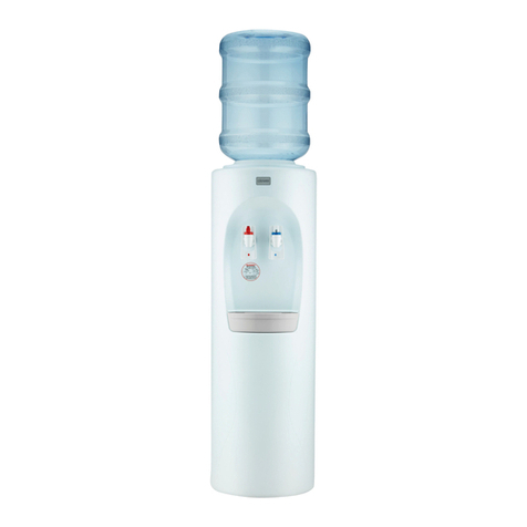
These water coolers were designed to provide large quantities of still and
carbonated cold water and hot.
They are easy to use and manufactured using top quality materials, offering
the utmost hygiene and ease of maintenance.
Indicated for household use, it can also be installed in other places like bars
DQGRI¿FHV7KH\VKRXOGDOZD\VEHLQVWDOOHGLQGRRUVDQGLQWKHHQYLURQPHQ-
tal conditions described under the “technical features” heading.
They are equipped with an internal cooling system, capable of supplying
water cooled to 3 ÷ 10°C.
They use a direct cooling system (hermetic ice bank).
Two types of water coolers are available:
Countertop (1)
Undercounter (2)
Some models can also provide carbonated water (WG-HWG versions),
in which case they need to be connected to a CO2 cylinder.
The cylinder should be placed inside the door or connected to the
inlet on the back of the appliance.
The countertop models have, as standard, a solenoid valve with safety
IXQFWLRQDQWLÀooding).
4

GENERAL VIEW
(I) Modello sottobanco - (GB) Undercounter model - (D) Unterbaummodelle -- (F) Modele sous plan - (E) Modelo debajo de mesón
723$
723:*
723+
723+:*
,1+
,1+:*
,1:*
,1)
OUT WATER
OUT AMB
OUT SODA
OUT HOT
FILL ICE BANK
IN WATER
IN CO2
FILL ICE BANK
IN WATER
319
19
20
20
21 25
251718
21 15
15
18
18
17
26
22
16
13
13
15
7
14
14
24
7
3
4
10
10
12
12
11
11
4
5
5
3
23
6
6
19
22
16
12
11
5
28
27 8
9
23
17
41424 113
10
7
3
2
27
6
7
12
11
5
17
4
87
9
110
13 6
14 3
8
9
2
15
5

1 Operator side
2 Rear side
3 Electrical power supply socket
4 Main switch
5 Cold water thermostat
6 Mains water inlet 3/4M or ø 8mm
7 CO2 inlet ø 6mm (WG model)
8 Cold water outlet
9 Carbonated water outlet (WG model)
10 Water entrance for basin loading
11 Level and basin unloading tube
12 Basin water level indicator
13 Label bearing the technical data and serial number
14 Heat outlet vent (do not cover)
15 Casing - easily removable to reach interior parts
GB
5HGÀRDWHULQGLFDWLQJWUD\¿OOLQJ
:DUQLQJOLJKWIRULQVXI¿FLHQWZDWHU:*PRGHOV
18 Network voltage warning light
19 Cold water button
20 Button for water at room temperature
21 Sparkling water button (WG models)
22 Small tank to collect dripping water.
It is removable and can be connected to a drain.
23 Hot water thermostat
24 Hot water switch
25 Hot water buttons (H - HWG models) must be pressed at the
same time for distribution
26 LED “HEATING” indicator lights up during the heating phase
27 Hot water outlet (OUT HOT)
28 Output water environment (OUT AMB)
6

D
4 TECHNICAL CHARACTERISTICSGB
(GB) WG model
(DK) modeller WG
(S) modell WG
(N) modell WG
586 ɦɨɞɟɥɢ:*
(GB) F model
(DK) model
F
(S) modell
F
(N) modell
F
586 ɦɨɞɟɥɢ)
Undercounter models
Modeller under skranken
Modeller som står under disken
Gulvmodeller
ɉɨɞɫɬɨɥɶɧɵɣɬɢɩɭɫɬɚɧɨɜɤɢ
A
B
H
260
300
407
A
B
H
260
235
407
4
(GB) Undercounter model
(GB) H model
( GB)
WG
model
(GB) HWG model
(GB) F model
7

ROOM TEMPERATURE:
Min 10°C
Max 43°C
H2OMY
TOP A
H2OMY
TOP WG
H2OMY
TOP H
H2OMY
TOP HWG
H2OMY
IN F
H2OMY
IN WG
H2OMY
IN H
H2OMY
IN WG
Water production
Lt/h
usg/h
15
3,96
15 (8)
3,96 (2.11)
15 (13)
3,9 (3,4)
15 (13)
3,96 (3,4)
15
3,96
15
3,96
15 (13)
3,9 (3,4)
15 (13)
3,96 (3,4)
Water outlet temperature
°C
°F
3 ÷ 10
37.4 ÷ 50
3 ÷ 10
37.4 ÷ 50
3 ÷ 10 (95)
38 ÷ 50 (203)
3 ÷ 10 (95)
38 ÷ 50 (203)
3 ÷ 10
37.4 ÷ 50
3 ÷ 10
37.4 ÷ 50
3 ÷ 10
(95)
38 ÷ 50
(203)
3 ÷ 10
(95)
38 ÷ 50
(203)
Continuous cold water production
L
usg
3
0.8
3
0.8
3
0.8
3
0.8
3
0.8
3
0.8
3
0.8
3
0.8
Cooling system
Banco di ghiaccio / Ice bank / Eisbank / Banc de glace / Banco de hielo
Compressor
HP 1/12
Total rated input
Watt 190 260 1390 1460 155 210 1355 1410
Supply
Volt/
Hz 220 - 240 / 1 / 50 Hz
Gross weight
kg
Ibs
14
31
18
40
15
33
22
48,5
14
31
18
40
15
33
21
46
ƔƔ Ɣ Ɣ
ƔƔ Ɣ Ɣ ƔƔ Ɣ Ɣ
ƔƔƔƔ
ƔƔ ƔƔ
Charge
g
FREON R134A
100 100 100 100 100 100 100 100
A-weighted sound pressure level
dB < 70 < 70 < 70 < 70 < 70 < 70 < 70 < 70
4.1 CONDITIONS OF THE SURROUNDINGS
8

HANDBOOK SECTION II
5HVHUYHGWRTXDOL¿HGRSHUDWRUV
9

During connection of the appliance to the mains water
supply , all pre -exixting tubes , gaskets and
joints placed between the appliance and the
water mains connection must be replaced with
new material to avoid contamination.
6-7cm
6-7cm
5 5.1 6
8
7
P
K
,IWKHPDLQVSUHVVXUHLVEHORZEDURUWKHÀRZUDWHLVOHVVWKDQOPLQ
¿WDGHYLFHFDSDEOHRILQFUHDVLQJWKHPDLQVSUHVVXUHH[ERRVWHUSXPS
or equivalent system).
N.B.: the pressure is especially important for those water
FRROHUV¿WWHGZLWKDFDUERQDWLRQGHYLFH
If the mains water pressure exceeds 3 bars, predispose a pressure re-
ducer capable of reducing the latter to the 1÷3 range.
7KLVZDWHUGLVSHQVHUFDQEHHTXLSSHGZLWKD:$7(5%/2&.DQWLÀRRG-
LQJGHYLFHRSWLRQDOWRSUHYHQWDQ\DFFLGHQWDOZDWHUOHDNV¿J2QFH
WKH:$7(5%/2&.GHYLFHKDVLQWHUYHQHG¿WWLQJKshould be disassem-
bled and button Ppressed to reset the device.
If instead of being connected directly to the aqueduct the machine is
connected to an autoclave pump, then it is necessary to install above the
ZDWHUVXSSO\DQ$17,6+2&.GHYLFHWRSUHYHQW³ZDWHUKDPPHUV´¿J
5.1 POSITIONING THE APPLIANCE
Position the appliance in the point of installation, away from sources of
eat and direct sunlight. We also advise against installing the appliance
outdoors and in very damp rooms.
Install the machine under the sink, keeping the vent Ccompletely clear.
Do not put anything in the way that could prevent or restrict the circula-
WLRQRIDLU¿J
The appliance should be positioned in such a way as to leave approximate-
ly 6 ÷ 7 cm of space free for air to circulate freely. Special ventilation grills/
slits must be prepared in the undercounter model’s housing compartment
WRIDYRXUGLVSRVDORIWKHKHDWSURGXFHGE\WKHUHIULJHUDWLQJFLUFXLW¿J
Make sure the water cooler is resting fully on all four supporting feet.
5.2 WATER CONNECTION TO THE MAINS
Before making the water connection, make sure the mains water pressure
is between 1 and 3 bars.
5 INSTALLATION
GB
10

(GB)Under counter models
MAX
MIN
FILL ICE BANK
FILL
IN WATER
MAX
MIN
FILL ICE BANK
FILL
IN WATER
9
10
IN WATER
11
FILL ICE BANK
IN WATER
9.1
12
A
A
R
T
T
R
E
R
J
J
T
S
A
R
T
P
F
5.3.1 Water connection
Countertop models: Join elements A, T, E, F, G (Fig.11).
Undercounter models: Push pipe Tonto coupling 11 exerting the correct
amount of pressure (Fig. 9.1).
5.3.2 Ice container emptying (for maintenance)
Disconnect the power supply cable from the outlet. To empty the ice tank af-
ter the ice melted, you just have to take the vertical level and tank discharge
tube PRIILWVVLWHDQGOHWWKHZDWHUÀRZ¿J$IWHUWKHLFHFRQWDLQHUKDV
been emptied (almost 3 litres), replace the tube in its place.
GB
Connection to the water mains is done using the Ttube provided (8 mm
diameter) and the A ¿WWLQJ SURYLGHG 'XULQJ FRQQHFWLRQ RI WKH DSSOLDQFH
to the mains water supply, all pre-existing tubes, gaskets and joints placed
between the appliance and the water mains connection must be replaced
with new material to avoid contamination.
5.3 ICE CONTAINER FILLING
Turn off the S switch (to ‘0’) on the machine beforehand.
Push tube Tin the connection IN WATER with the necessary pressure.
Open tap Rand allow water to enter ice bank slowly until the water level in
the vertical transparent (Fig. 9) pipe (P) reaches the position shown by plate
“Fill”. Close tap R. Take off the tube Tpushing with a 8key on the locking
ring and simultaneously pulling the tube (Fig. 10). Insert immediately the
red cap Jon the connection FILL ICE BANK with the right pressure.
11

Warning! Before using the machine proceed
with the sanitation (see relative paragraph).
6 STARTINGGB
Warning! If the appliance has been laid down or turned upside
down, you should wait at least 8 hours before starting it.
6.1 ELECTRICITY CONNECTION
Connection to the mains electricity supply is carried out by connecting the
plug to a mains socket. The supply socket must be equipped with an ef-
¿FLHQWHDUWKSODWHDQGLWPXVWEHVL]HGIRUWKHORDG RI WKH DSSOLDQFH VHH
technical characteristics).
0DNH VXUH WKDW WKH PDLQV YROWDJH FRUUHVSRQGV ZLWK ZKDW LV VSHFL¿HG RQ WKH
data plate. Make sure that there is an omnipolar switch above the socket with a
minimum contact break of 3 mm protected by fuses of suitable amperage for the
absorption of the appliance itself (see technical characteristics and data plate).
Turn on the water tap and make sure there are no leaks.
Turn on the main ON/OFF switch 4.
Turn the tap to the position marked to eliminate all remaining air in
the soda water circuit (WG models).
13 14
IN CO2
1615
R
5
4
Turn the tap to the position marked to eliminate all remaining air in
the cold water circuit.
Adjust cold water thermostat 5depending on use and season (positions
recommended from 4 to 7).
Connect the machine to a mains electrical network protected by a circuit
breaker with a sensitivity equal to or less than 30 mA.
6.2 CO
2
GAS CYLINDER CONNECTION (CARBON DIOXIDE)
In this water cooler model, the CO2can be connected only outside the ma-
FKLQH¿JDOORZLQJWKHXVHRIUHFKDUJHDEOHF\OLQGHUVDVZHOO
CAUTION: do not pass the cylinder’s connecting pipe in front of the
KHDWRXWOHWYHQW¿J
Take the ø6 mm pipe out of the installation kit and connect it to the R
SUHVVXUHUHGXFHURQWKHF\OLQGHU¿J
Insert the other end of the pipe on the IN CO2connector at the top of the
device; make sure you insert it correctly.
The cylinder is provided with a sealing valve which will open during reducer as-
sembly and will close automatically during disconnection. The reducer regula-
tion screw Ris already calibrated in the optimal pressure setting (approximately
3.5 bar). In any case, the quantity of gas supplied can be increased by turning
the screw in the clockwise direction, and vice versa. 600 g. rechargeable CO
2
cylinders can charge approximately 120 liters of water.
12

(GB)Undercounter models
NO
WATER
NO
WATER
IN CO2
IN CO2
19
17 18
V
Q
R
6 SETTING UP THE SPARKLING WATER (WG and HWG models)
INSTALLATION OF RECHARGEABLE CYLINDERS ( B-RIC)
,WLVDOVRSRVVLEOHWRLQVWDOOUH¿OODEOHF\OLQGHUV%5,&
Remove the ø6mm tube from the installation kit and connect it to the
pressure reducer Rof the rechargeable (B-RIC) cylinder to the IN CO2
LQOHWRQWKHWRSSDQHO¿J
Screw the pressure reducer cap to the cylinder attachment paying atten-
tion to the gasket.
Open the cylinder valve V.
The screw for regulating the reduction valve Rhas already been calibrated
to the optimal pressure setting (approximately 3,5 bar).
In any case, the quantity of gas supplied can be increased by turning the
screw in the clockwise direction, or decreased by turning it in the anti-clock-
ZLVH GLUHFWLRQ ¿J 5HFKDUJHDEOH &22cylinders can charge approxi-
mately 140 liters of water.
NOTICE! Rechargeable cylinders are empty when supplied. Have
WKHF\OLQGHU¿OOHGZLWKJDVE\WKHQHDUHVWDXWKRUL]HGGLVWULEXWRU
Ask only for CO2 (carbon dioxide) for “food products.”
GB
To start the carbonation device:
Press the pushbutton for carbonated water .
/HWDIHZOLWUHVRIZDWHUÀRZXQWLOFDUERQDWHGZDWHUEHJLQVWRFRPHRXW
Attention!
The results of pressure variations on carbonation will only have
effect when at least 2 litres of water have been drained off.
Advice on using the appliance for carbonated water
To guarantee the correct operation of the pump in time, the appliance
must always be operated with water in the cooling circuit.
,I PDLQV ZDWHU LV LQVXI¿FLHQW D SURWHFWLRQ V\VWHP LQWHUYHQHV DQG
blocks pump functioning (the NO WATER warning light is illuminated)
To restore functioning the apparatus must be disconnected from the
HOHFWULFDOQHWZRUNDQGUHFRQQHFWHGZKHQWKHUHLVVXI¿FLHQWZDWHULQ
the mains system.
13

Attention: to carry out this or any other maintenance
operation requiring the machine casing to be opened, use
protective gloves to avoid being cut by the sharp edges of
the sheet steel
19.1
20 21
19.2
V
14

The quality of the carbonation process also depends on the temperature of
the water, which means you should wait for the water cooler to have cooled
WKH ZDWHU GRZQ VXI¿FLHQWO\ XSRQ LQVWDOODWLRQ DQG WKH LFH EDQN KDV EHHQ
formed. Both still and carbonated water can be dispensed by pressing the
relative buttons after approximately 40 minutes.
NOTICE
CAUTION! AFTER TRANSPORTING, STORING AND USING CO2CYL-
INDERS, FOLLOW LOCAL REGULATIONS CONCERNING THEIR USE.
GB
6.3 CARBONATION DEVICE DRAINAGE
When installing the appliance, or if the water cooler has no water left inside
it, a few air bubbles may enter the carbonation device.
These air bubbles could diminish the quality of the carbonation process,
and we therefore recommend you remove them:
Unscrew the cylinder from the reducer
Remove the casing
Drain the circuit by pulling the outlet valve ring V¿J
Re-connect CO2cylinder to the reducer
Drain off at least two litres of sparkling water
Replace the casing.
15

22 23
24
10
10
2323
7KHVH ZDWHU FRROHUV DUH ¿WWHG ZLWK D OLWUH VWDLQOHVV VWHHO WDQNIRU WKH
production and storage of water heated to 95°C max.
A special safety system allows for hot water to be dispensed only if both the
button and SAFETY buttons (red button) are pressed simultaneously.
Identify the red switch 10; on the TOP model it is placed on the back
¿JZKLOHRQWKH,1PRGHOLWLVRQWKHRSHUDWRUVLGHSDQHO¿J
Keep the switch off 10 (pos.O).
Keep the buttons
(
DQG6$)(7<SUHVVHGDWWKHVDPHWLPHWR¿OO
Turn on switch 10.
Set the desired temperature on thermostat 23; the temperature can be
set from a minimum of 60°C to a maximum of 95°C. The 23 thermostat
is placed on the back on the TOP models and on the IN models.
6.3 HYGIENIC CLEANING
Once you have checked that the appliance operates correctly, pro-
ceed with the “internal cleaning and hygienic cleaning” phase as de-
scribed in chap. 8.
When switch 10 turns off, the water has reached the required tem-
perature.
Warning!
Hot water at 95°C produces steam under pressure.
WKHWDQNZLWKKRWZDWHUXQWLODFRQVWDQWÀRZH[LWVWKHGLVSHQVHU
This is extremely important and hould be done before you
turn switch 10 on , to avoid any permanent damage
being caused to the hot water tank.
6 STARTING WITH HOT WATER (H and HWG models)
GB
16

SUBJECT HOW HOW OFTEN
Cleaning the outside of the appliance
Clean the external part with a damp cloth, do not use solvents or abrasive detergents.
Monthly
Replacing the CO2 cylinders Follow the instructions provided in paragraph 6.2. When the manometer falls
below 1 bar.
Cleaning the water collection tray Clean the tray and remove any residue. Weekly
&OHDQLQJWKHFRROLQJFRQGHQVHU¿J
Remove all dust and dirt with a domestic vacuum cleaner or similar appliance.
Do not use compressed air jets.
Do not use wire brushes.
Monthly
Water replacement in the ice bank tank
Switch the apparatus off and wait about 1 hour for it to defrost.
Empty the water using the level and basin unloading tube
P
(see section 5.3.2)
Restore the water level in the ice bank tank as described in the INSTALLA-
TION chapter.
If the machine has been
turned off for a long time
Power lead Check the condition and intactness of the power lead.
Water connection check Check the condition and intactness of the water supply pipe.
Check for any leak.
&OHDQLQJWKHPHFKDQLFDOZDWHU¿OWHU723
models)
'LVDVVHPEOHWKHLQOHWSLSH¿WWLQJSXOOWKH¿OWHUXVLQJSOLHUVDQGUHPRYHDQ\
LPSXULWLHV¿J Every month
Cleaning the water dispensing spouts Remove the steel nozzle using the appropriate spanner and eliminate all the
OLPHVWRQHZLWKDIRRGGHVFDOLQJVROXWLRQ¿J
Depending on the hardness
of the water from the mains
'HFDOFL¿FDWLRQWKHPDFKLQH &KHFNDQGLIQHFHVVDU\GHVFDOLQJWKHZDWHUVXSSO\KRVHDQG¿OWHU Annually
7 ROUTINE MAINTENANCEGB
5LVHUYDWRDGRSHUDWRULTXDOL¿FDWL5HVHUYHGWRTXDOL¿HGRSHUDWRUV)UTXDOL¿]LHUWH%HWULHEHQ5HVpUYpDX[SHUVRQQHOTXDOL¿p5HVHUYDGRDWpFQLFRVFDOL¿FDGRV
Maintenance operations should be carried out by
a TXDOL¿HGSURIHVVLRQDO
25.1 25.2
17

0DLQWHQDQFHRSHUDWLRQVVKRXOGEHFDUULHGRXWE\DTXDOL¿HG
professional
8 INTERNAL CLEANING/HYGIENIC CLEANING
8.1 HYGIENIC CLEANING
WARNING! Given that the products used for the hygienic cleaning procedure
contain corrosive acidic and alkaline substances, disposable gloves and
protective eye wear should be worn at all times. When performing the
hygienic cleaning procedure, please keep to the product reaction times,
sanitising liquid percentages and quantities of water for rinsing.
The operation of higienization/sterilization has to be carried out every
time the refrigerator is installed and:
- every 6 months when it is used (*).
- HYHU\WLPHWKHZDWHU¿OWHULVFKDQJHG
- after an inoperative period of one or more weeks.
(*) If the refrigerator is installed in Hospitals, Schools, Old people’s homes,
or Clinics, it is recommended to sterilize it every 3 months.
Hygienic cleaning solution preparation
Prepare 5 litres of water.
Add to it 5% of “hydrogen peroxide” at 100 volumes; for the doses, use a
graded measure or an ordinary syringe.
GB
1%LI\RXXVHFRPPHUFLDOK\JLHQLFFOHDQLQJVROXWLRQVNHHSWRWKHLQVWUXF-
WLRQVSURYLGHGE\WKHPDQXIDFWXUHUDQGLQFOXGHGLQWKHSDFNDJH
With the help of a pump P, connect the appliance’s water inlet to the
container with the disinfecting solution.
Start the pump, allowing the disinfectant to enter the appliance, then turn
RQWKHWDSVWR HQDEOHWKHK\JLHQLFFOHDQLQJVROXWLRQWRÀRZ WKURXJKRXW
the entire hydraulic circuit, right through to the water dispensing spout.
Before the solution runs out, stop the pump and interrupt the dispensing.
Leave the solution to do its work for minimum 20 minutes.
Reconnect the appliance to the mains water supply.
/HWDWOHDVWOLWUHVRIZDWHUÀRZRXWRIWKHWDSVVRDVWRULQVHWKHK\GUDX-
lic system suitably, before using the appliance again.
8.2 LIMESCALE REMOVAL (H model)
Limescale should be removed from the hot water tank regularly, to avoid
the build-up of limescale deposits. This should be done at least once a
\HDURUZKHQ\RXQRWLFHWKDWKRWZDWHUKDVVRPHGLI¿FXOW\ÀRZLQJRXW
IN
WATER
26
P
18

0DLQWHQDQFHRSHUDWLRQVVKRXOGEHFDUULHGRXWE\DTXDOL¿HG
professional
9 DRAINING CONNECTION
The TOP models have a tray prepared to be pierced and connected to a
draining tube.
The draining tube passes below the machine.
For draining, use a soft silicon tube, with an internal diameter of 4 mm.
Pierce the tray at the indicated point, using a 3 – 3.5 mm drill bit doing a
state of the art job.
GB
27
19

$120$/< 3266,%/(&$86( ,17(59(17,21
WKH FRPSUHVVRU ZLOO
QRWVWDUW
SRZHUIDLOXUH FKHFNWKDWWKHUHLVYROWDJHLQWKHSOXJ
WKHUPRVWDWRQWKHRIISRVLWLRQRUVHWWRWKHPL
QLPXP
DGMXVWWKHWKHUPRVWDWSRVLWLRQ
IDXOW\WKHUPRVWDW UHSODFHWKHWKHUPRVWD
W
WKHRYHUORDGSURWHFWLRQRIWKHFRPSUHVVRULVIDXOW\
UHSODFHLW
WKHVWDUWLQJUHOD\LVIDXOW\
UHSODFHLW
WKHVWDUWLQJFDSDFLWRULVIDXOW\
UHSODFHLW
WKHFRPSUHVVRULVIDXOW\
UHSODFHLW
WKHZDWHULVFROGEXW
WKHDSSOLDQFHLVRSH
UDWLQJH[FHVVLYHO\RU
QRQVWRS
OLWWOHYHQWLODWLRQ
SODFHWKHDSSOLDQFHDZD\IURPWKHZDOO
WKHFRQGHQVHULVGLUW\RUFRYHUHG
FOHDQWKHFRQGHQVHURUIUHHLWRILWVREVWDFOHV
WKHWKHUPRVWDWLVRQPD[LPXPFROGSRVLWLRQ
DGMXVWLW
WKHURRPWHPSHUDWXUHLVKLJKHUWKDQ&
LW LV QRUPDO WKDW WKH DSSOLDQFH ZRUNV DW D FRQWLQXRXVO\ KLJK URRP
WHPSHUDWXUH
WKHFRPSUHVVRU
ZRUNVFRQWLQXRXVO\
EXWWKHZDWHULVQRW
FROG
JDVOHDNIURPWKHFRROLQJV\VWHP FRQWDFWDVSHFLDOLVHGWHFKQLFLDQUHIULJHUDWLRQLVW
WKHFRPSUHVVRULVIDXOW\
UHSODFHWKHFRPSUHVVRU
&22/,1*6<67(0
WRRPXFKQRLVHFRP
LQJ IURP WKH DSSOL
DQFHEXWLWLVZRUN
LQJQRUPDOO\
WKHPDFKLQHLVQRWOHYHOOHG
OHYHOWKHDSSOLDQFHXVLQJWKHDGMXVWDEOHIHHW
D IHZ SLSHV DUH WRXFKLQJ VRPH SDUWV LQVLGH WKH
DSSOLDQFHWKXVFDXVLQJLWWRYLEUDWH
DGMXVWWKHSRVLWLRQRIWKHSLSHVPDNLQJVXUHWKH\GRQRWWRXFKDQ\
RWKHUSDUWV
FROG ZDWHU FRPHV RXW
VORZO\RUQRWDWDOO
ORZSUHVVXUHRIWKHLQOHWZDWHU
WDNHVWHSVWRLQFUHDVHWKHSUHVVXUHDXWRFODYH
IDXOW\VROHQRLGYDOYH
UHSODFHLW
FORJJHGZDWHU¿OWHU
UHSODFHLW
WKHWHPSHUDWXUHDGMXVWHULVIDXOW\DQGFDXVHV
FRPSOHWHIUHH]LQJRIWKHLFHFRPSDUWPHQW
PDNHWKHLFHPHOW
UHSODFHWKHWHPSHUDWXUHDGMXVWHU
&$5%21$7,1*6<67(0
WKH FDUERQDWHG ZDWHU
LVQRWYHU\¿]]\RUQRW
DWDOO
WKHSUHVVXUHRIWKHJDVLQWKHFRUHGXFHULV
VHWWROHVVWKDQEDUV
LQFUHDVHXSWR±EDUV
FRF\OLQGHUHPSW\ UHSODFHLW
WKHWHPSHUDWXUHRIWKHRXWOHWZDWHULVKLJK DGMXVWWKHSRVLWLRQRIWKHWKHUPRVWDWWRPD[LPXP
DLUEXEEOHVLQVLGHWKHFDUERQDWRU FOHDQRXWWKHFDUERQDWRU
RQO\JDVFRPHVRXWRI
WKH FDUERQDWHG ZDWHU
RXWOHW
WKHOHYHOSUREHVDUHGLUW\ FRQWURODQGUHSODFH
WKHSXPSWXUQVFRQWLQXRXVO\ QRZDWHULVHQWHULQJRUWKHZDWHU¿OWHULVEORFNHG
WKH SXPS WXUQV FRQWLQXRXVO\ LQOHW ZDWHU LV
SUHVHQW
WKH SLSH ¿WWLQJ LQWR WKH FDUERQDWRU LV REVWUXFWHG GLVDVVHPEOH DQG
FOHDQ
WKHSXPSLVEORFNHGRUWKHSXPSPRWRULVQRW
ZRUNLQJ
FKHFNLWDQGUHSODFHLW
WKHOHYHOFRQWUROOHULVIDXOW\ FRQWURODQGUHSODFH
WKH SXPS VDIHW\ GHYLFH KDV LQWHUYHQHG QR
ZDWHU
FKHFNWKDWWKHUHLVSUHVVXUHLQWKHQHWZRUN
GLVFRQQHFWDQGUHFRQQHFWWKHPDFKLQHIURPWKHHOHFWULFDOQHWZRUNWRUH
VHWLW
FRQWLQXRXV GULSSLQJ
IURPWKHRXWOHWV
GLUW\VROHQRLGYDOYH GLVDVVPHEOHWKHVROHQRLGYDOYHDQGFOHDQLW
WKH VWLOO ZDWHU FRPHV
RXWFDUERQDWHG
WKHUHLVDVKRUWDJHRILQOHWZDWHU GLVDVVHPEOHDQGFOHDQRUUHSODFH
(1
&22/,1*6<67(0
20
This manual suits for next models
6
Table of contents
Other MERQUIP Water Dispenser manuals
Popular Water Dispenser manuals by other brands

WaterLogic
WaterLogic WL Max Technical manual

Everpure
Everpure EV941000 Specification sheet

Judo
Judo i-soft Installation and operating instructions

TZS First AUSTRIA
TZS First AUSTRIA FA-5448-6 instruction manual

Monarch Water
Monarch Water MC-11 install guide

AAFIRST
AAFIRST Arctic Revolution 75B installation instructions