merten REG-K User manual
D
Dieses Gerät ist ein Produkt des INSTABUS-EIB-Sys-
tems und entspricht den KNX-Richtlinien. Detaillierte
Fachkenntnisse durch instabus-Schulungen werden
zum Verständnis vorausgesetzt. Die Funktion des Gerä-
tes ist softwareabhängig. Detaillierte Informationen,
welche Software geladen werden kann und welcher
Funktionsumfang sich damit ergibt, sowie die Software
selbst sind der Merten-Produktdatenbank zu entneh-
men. Planung, Installation und Inbetriebnahme des Ge-
rätes erfolgen mit Hilfe einer KNX-zertifizierten
Software. Die Produktdatenbank sowie die technischen
Beschreibungen finden Sie stets aktuell im Internet un-
ter www.merten.de.
Der Koppler verbindet datentechnisch zwei instabus
KNX/EIB Linien miteinander und gewährleistet eine gal-
vanische Trennung zwischen diesen Linien. Die genaue
Funktion des Gerätes wird durch die Adressierung und
die gewählte Applikation festgelegt
Linienkoppler LK:
Phys. Adresse X.Y.0
Verbindung einer Linie mit einer Hauptlinie (HL). Wahl-
weise mit oder ohne Filterfunktion. Der Koppler ist lo-
gisch der untergeordneten Linie zugeordnet.
Bereichskoppler BK:
Phys. Adresse X.0.0
Verbindung einer Hauptlinie (HL) mit einer Bereichslinie
(BL). Wahlweise mit oder ohne Filterfunktion. Der Kopp-
ler ist logisch der untergeordneten Linie zugeordnet.
Verstärker V:
Phys. Adresse X.Y.Z
Aufbereitung und Wiederholung von Telegrammen auf
einer Linie, keine Filterfunktion. Unterteilung einer Linie
in max. 4 unabhängige Liniensegmente => max. 3 par-
allelgeschaltete Linienverstärker pro Linie. Für jedes Li-
niensegment ist eine separate Spannungsversorgung
(SV) inklusive Drossel (DR) notwendig.
EIB-Systeminformation
Das können Sie mit dem
Bereichs- Linienkoppler tun
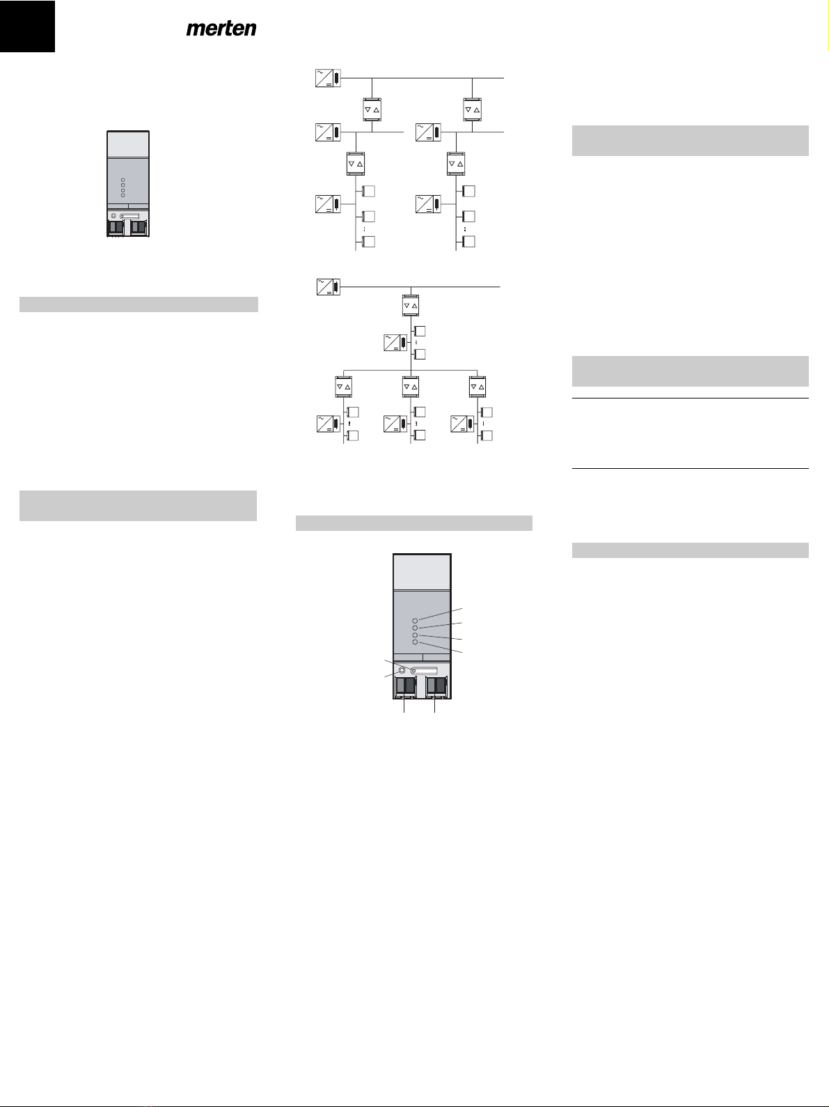
Prinzipschaltbilder eines instabus KNX/EIB
Systems
Einsatz als Bereichs- und Linienkoppler (BK und LK)
Einsatz als Linienkoppler LK und Verstärker V
(TLN = Busteilnehmer, DR = Drossel, SV = Spannungs-
versorgung)
Jede Linie benötigt eine separate Spannungsversor-
gung.
1Programmiertaste
2Programmier-LED, rot
3Betriebs-LED, grün
4LED gelb, Datenempfang auf übergeordneter Linie
(HL)
5LED gelb, Datenempfang auf untergeordneter Li-
nie (UL)
6Diagnose LED, rot
7Anschlussklemme für untergeordnete Linie (UL)
8Anschlussklemme für übergeordnete Linie (HL)
Funktion Diagnose-LED („DIAG“), rot
LED aus: Standard Filtertabelle geladen,
keine Fehler
LED dauernd ein: Standard Filtertabelle nicht gela-
den,
keine Fehler
(Keine Unterscheidung zwischen
„nicht projektiert“ und
„alle Gruppenadressen durchlas-
sen“)
LED blinkend : Fehler vorhanden
(gemäß Fehlerflags im Gerät)
Bedien- und Anzeigeelemente
TLN
TLN
TLN
SV DR
LK
HL1
BK
SV DR
TLN
TLN
TLN
SV DR
LK
HL2
BK
BL
SV DR SV DR
TLN
TLN
SV DR
V
HL
SV DR
TLN
TLN
V
SV DR
TLN
TLN
V
SV DR
TLN
TLN
LK
SV DR
(2)
(1)
(3)
(5)
(6)
(4)
RUN
HL
UL
DIAG
HL UL
(8) (7)
Funktion Betriebs-LED („RUN“), grün
LED aus: Gerät aus, keine Spannung auf
übergeordneter Linie
LED dauernd ein: Gerät ein; Spannung auf beiden
Linien
LED blinkend: keine Spannung auf
untergeordneter Linie
1Aufschnappen auf Hutprofilschiene 35 x 7,5 mm
nach DIN EN 50022.
2Der Anschluss der übergeordneten Linie erfolgt
mit der linken Anschlussklemme (Klemme "HL").
Über diesen Anschluss wird die Geräteelektronik
versorgt. Dies ermöglicht es, über die übergeord-
nete Linie einen Busspannungsausfall der unterge-
ordneten Linie zu melden.
3Die untergeordnete Linie wird an der rechten An-
schlussklemme (Klemme "UL") angeschlossen.
|Demontage-Hinweis: Anschlussklemme nicht
von unten heraushebeln! Die Busspannung kann
dabei kurzgeschlossen werden und für die Zeit
des Kurzschlusses ausfallen.
¼
Lebensgefahr:
Alle Tätigkeiten am Gerät dürfen nur durch Elek-
trofachkräfte erfolgen. Beachten Sie die länder-
spezifischen Vorschriften sowie die gültigen EIB-
Richtlinien!
1Physikalische Adresse aus der ETS per EIB in den
Universal-Dimmaktor laden.
2Konfigurationseinstellungen in der ETS vornehmen
und übertragen.
Versorgung
instabus: 21 – 30 V DC
über die übergeordnete
Linie
Stromaufnahme
übergeordnete Linie: ca. 6 mA
untergeordnete Linie:ca. 8 mA
Anschluss : Anschlussklemme für
über- und untergeordnete
Linie
Montage: Aufschnappen auf
Hutschiene
Umgebungstemperatur: -5 °C bis +45 °C
Lagertemperatur.: -25 °C bis + 70 °C
Schutzart: IP 20 nach EN 60529
Schutzklasse: III nach EN 61140
Einbaubreite: 36 mm (2 TE)
Gewicht: ca. 90 g
Merten GmbH & Co. KG,
Lösungen für intelligente Gebäude
Service Center, Fritz-Kotz-Straße 8,
Industriegebiet Bomig-West
D-51674 Wiehl
Telefon: +49 2261 702-204
Telefax: +49 2261 702-136
E-Mail: [email protected]
Internet: www.merten.de
InfoLine:
Telefon: +49 1805 212581* oder +49 800 63783640
Telefax: +49 1805 212582* oder +49 800 63783630
E-Mail: [email protected]
* kostenpflichtig / fee required
So montieren Sie den Bereichs- Linien-
koppler
So nehmen Sie den Bereichs- Linien-
koppler in Betrieb
Technische Daten
Bereichs-Linienkoppler REG-K
Gebrauchsanleitung
Art.-Nr. 680204
RUN
HL
UL
DIAG
HL UL
V6802-582-00 08/06

GB
This device is a product of the KNX/EIB instabus-KNX/
EIB system and complies with KNX directives. Detailed
technical knowledge obtained in KNX/EIB training cour-
ses is a prerequisite to proper understanding.The func-
tionality of this device depends on the software.
Detailed information on loadable software and attainab-
le functionality as well as the software itself can be ob-
tained from the manufacturer's product database.
Planning, installation and commissioning of the unit is
effected by means of KNX-certified software. An up-
dated version of the product database and the technical
descriptions are available in the Internet at www.mer-
ten.de.
The coupler connects two instabus KNX/EIB data lines
and ensures the electrical separation of these lines
from one another. The definite functions of the device
are defined by addressing and parameterization.
Line coupler LK:
Physical address X.0.0
Connection of a main line (HL) with an area line (BL). Al-
ternatively with or without filter function. The coupler
belongs logically to the subordinate line.
Area coupler BK:
Physical address X.0.0
Connection of a main line (HL) with an area line (BL). Al-
ternatively with or without filter function. The coupler
belongs logically to the subordinate line.
Amplifier V:
Physical address X.Y.Z
Handling and repetition of telegrams on a line, no filter
function. Division of a line into max. 4 independent line
segments => max. 3 line amplifiers connected in paral-
lel per line (FIG. C). Each line segment requires a sepa-
rate power supply (SV) including a choke (DR).
EIB-System Information
What you can do with the Area/Line
Coupler
Schematics of an instabus KNX/EIB system
Use as area and line coupler (BK and LK)
Use as line coupler LK and amplifier V
(TLN = bus subscriber, DR = choke, SV = instabus KNX/
EIB power supply)
Each line requires a separate power supply.
1programming button
2programming LED, red
3operation LED, green
4LED amber, incoming data on superordinate line
(HL)
5LED amber, incoming data on subordinate line Li-
nie (UL)
6diagnosis LED, red
7connecting terminal for superordinate line (HL)
8connecting terminal for subordinate line (UL)
Function of diagnosis LED ("DIAG") red
LED off: Telegrams are filtered or blocked
(both directions)
LED on: Telegrams are retransmitted
without being filtered (at least one
direction)
LED flashing: error detected (as per error flags
in device)
Controls and indicators
TLN
TLN
TLN
SV DR
LK
HL1
BK
SV DR
TLN
TLN
TLN
SV DR
LK
HL2
BK
BL
SV DR SV DR
TLN
TLN
SV DR
V
HL
SV DR
TLN
TLN
V
SV DR
TLN
TLN
V
SV DR
TLN
TLN
LK
SV DR
(2)
(1)
(3)
(5)
(6)
(4)
RUN
HL
UL
DIAG
HL UL
(8) (7)
Function of operation LED ("RUN") green
LED off: device off,
no voltage on superordinate line
LED on: device on,
voltage on both lines
LED flashing: no voltage on subordinate line
1The device is snap-fastened on the DIN rail until the
latch is heard to engage, with the connecting termi-
nals pointing downwards
2The superordinate line is connected with the left-
hand terminal (terminal "HL"). This terminal sup-
plies power to the device electronics so that it is
possible to report a bus voltage failure of the sub-
ordinate via the superordinate line.
3The subordinate line is connected to the right-hand
terminal (terminal "UL").
|Removal info: Do not lever out the connecting
termianal from below. Risk of shorting the bus
voltage which is not available during the short-cir-
cuit.
¼
Risk of fatal injury from electrical current.
All work carried out on the device may only be per-
formed by skilled electricians.
The country-specific regulations and the valid KNX
guidelines must be followed.
1Load the physical address into the push-button from
the ETS via the KNX bus.
2Complete the required configuration settings in the
ETS, and transfer the configuration via EIB into the
coupler.
Supply
instabus KNX/EIB: 21 - 30 V DC
from superordinate line
Current consumption
superordinate line: approx. 6 mA
subordinate line: approx. 8 mA
Connection: KNX/EIB instabus terminal
for superordinate and
subordinate line
Fitting: snap-fastening on DIN
rail
Ambient temperature: -5 °C ... +45 °C
Storage temperature.: -25 °C ... + 70 °C
Type of protection: IP 20 in acc. with
EN 60529
Safety class: III in acc. with
EN 61140
Installation width: 36 mm (2 modules)
Weight: approx. 90 g
Merten GmbH & Co. KG,
Solutions for intelligent buildings
Service Center, Fritz-Kotz-Straße 8,
Industriegebiet Bomig-West
D-51674 Wiehl
Phone: +49 2261 702-204
Fax: +49 2261 702-136
E-Mail: [email protected]
Internet: www.merten.de
InfoLine:
Phone: +49 1805 212581* or +49 800 63783640
Fax: +49 1805 212582* or +49 800 63783630
E-Mail: [email protected]
* fee required
How to install the Area/Line Coupler
How to set up the Area/Line Coupler
Te c h n i c a l d a t a
Area/Line Coupler REG-K
Operating instructions
Art.-Nr. 680204
RUN
HL
UL
DIAG
HL UL
V6802-582-00 08/06
Table of contents
Languages:
Other merten Switch manuals


