merten REG/6-fach User manual
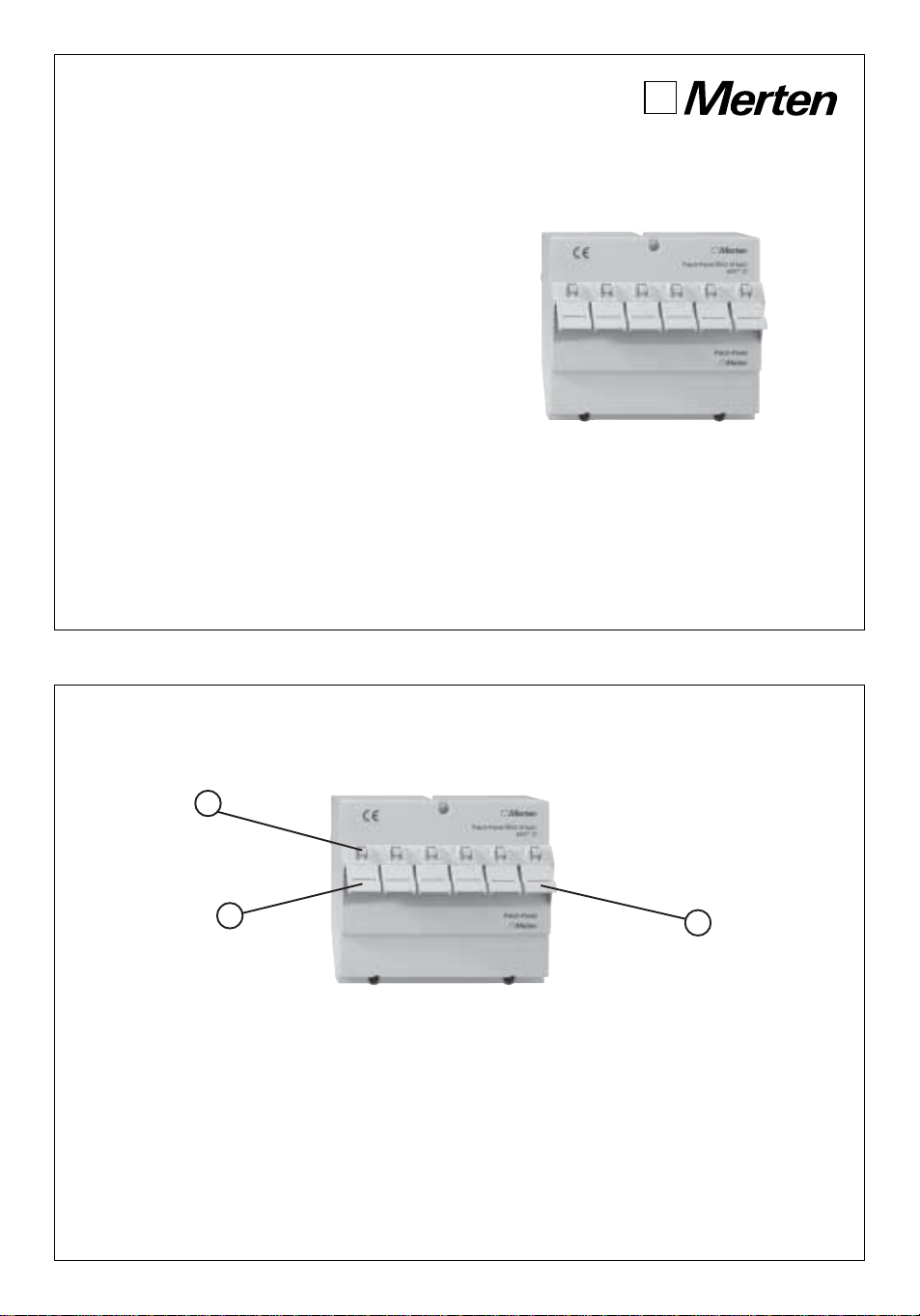
Patch-Panel REG/6-fach
Gebrauchsanweisung
Operating Instructions
© 2002 293 457 Stand 10.02 Gedruckt auf 100 % chlorfrei gebleichtem Papier
BeiWarenrücksendungen auf Grund von
Beanstandungen wenden Sie sich bitte an unser
Service Center:
Merten GmbH & Co.KG, Systemlösungen für die
Elektrotechnik, Service Center
Fritz-Kotz-Straße8, Industriegebiet Bomig-West
D-51674Wiehl
Telefon:+49 (0) 22 61/702-204
Telefax:+49 (0) 22 61/702-136
E-Mail:servicecenter@merten.de
Internet:www.merten.de
Bei technischen Fragen wenden Sie sich bitte an
unsere InfoLine:
Telefon:01 805/21 25 81 oder 0 800/63 78 36 40
Telefax:01 805/21 25 82 oder 0 800/63 78 36 30
E-Mail:infoline@merten.de
2
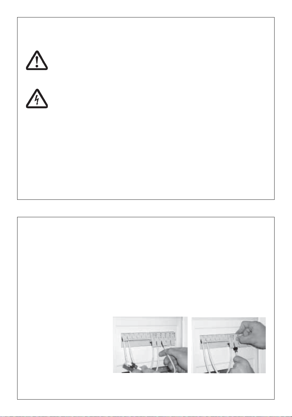
1 Entriegelungsknopf
2 Staubschutzkappe
Zubehör /Accessory (optional)
Switch REG/5-fach 4657 11
Release knob
Bild 1/Fig. 1
1
2
2
Geräteübersicht/Overview
Dust cover
We (Merten GmbH &Co KG) de-
clare, that the patch-panel REG is
in accordance with the ”Basic re-
quirements” and other relevant
Wir (Merten GmbH & Co KG) er-
klären, dass der Patch-Panel
REG mit den "Grundlegenden An-
forderungen" und anderen rele-
vanten Bestimmungen der Richt-
linie 1999/5/EG des europäi-
schen Parlaments und des Ra-
tes vom 09.03.99 über Funkan-
lagen und Telekommunikations-
endeinrichtungen und die ge-
genseitige Anerkennung ihrer
Konformität (R&TTE) überein-
stimmt.
Der Patch-Panel REG wird im
Rahmen eines umfassenden
Qualitätssicherungssystems nach
ISO 9001 mit der Registrier-Nr.
886 gefertigt.
Die Prüfung der "Grundlegenden
Anforderungen" der R&TTE-
Richtlinie bzw. des FTEG bezüg-
lich EMV und Sicherheitsanforde-
rungen erfolgen im von der CE-
TECOM ICT Services GmbH (Be-
nannte Stelle mit der EU-Kenn-Nr.
0682) unter der Nummer
Q812412N zertifizierten Testlabor.
Herstellererklärung/Manufacturing Declaration
regulations of the "Directive
1999/5/EC of the European Par-
liament and the Council of 9th
March 1999 on radio equipment
and telecommunications equip-
ment and the mutual recogni-
tion of their conformity"
(R&TTE).
The patch-panel REG is being
manufactured within a comprising
quality assurance system accord-
ing to ISO 9001 with registratioon
number 886.
The testing of the “Basic require-
ments” of the R&TTE-directive
regarding EMC and safety regula-
tions take place in the certified
testing laboratory (Q812412N)
registrated by CETECOM ICT
Services GmbH (notified body
with EC identificaton number
0682).
19

3
Inhaltsverzeichnis Geräteübersicht. .............................................................................. 2
Allgemeines. ..................................................................................... 5
Anwendungsbeispiel .......................................................................... 5
Inbetriebnahme
Montage.............................................................................................. 6
Installation .......................................................................................... 7
Kabelvorbereitung............................................................................ 8
Anschlussbelegung ............................................................................ 9
Farbcode............................................................................................. 9
Technische Daten. .......................................................................... 10
Herstellererklärung. ....................................................................... 19
Table of contents Overview. .......................................................................................... 2
General. ........................................................................................... 11
Application Sample .......................................................................... 11
Putting into Operation
Mounting........................................................................................... 12
Installation ........................................................................................ 13
Cable Preparing.............................................................................. 14
Terminal Assignment........................................................................ 15
Colorcode ......................................................................................... 15
Technical Data. ............................................................................... 16
Manufacturing Declaration............................................................ 19
Notizen
5
Allgemeines
Das REG-Patchpanel, 6 Port ist
eine passive Netzwerkkompo-
nente entsprechend Category 5e/
Class D zur Verkabelung von bis
zu 6 Endgeräten.
Das Patchpanel benötigt keinerlei
Bedienelemente für den Benutzer
oder Installateur.
Es ist als Reiheneinbaugerät
(REG) für die Montage in der
Elektroverteilung bzw. auf der
Hutschiene eines Verteilerkastens
(KVK) vorgesehen.
Um eine Beeinflussung des Netz-
werkes durch Störungen/Verände-
rungen im Bereich der 230-V-In-
stallation zu vermeiden, trennen
Sie bitte stets die Spannungs-
versorgung der aktiven Geräte
sowie der Datenendgeräte (PC
usw.) (z. B. SR5) von denen an-
derer Verbraucher (Kaffeemaschi-
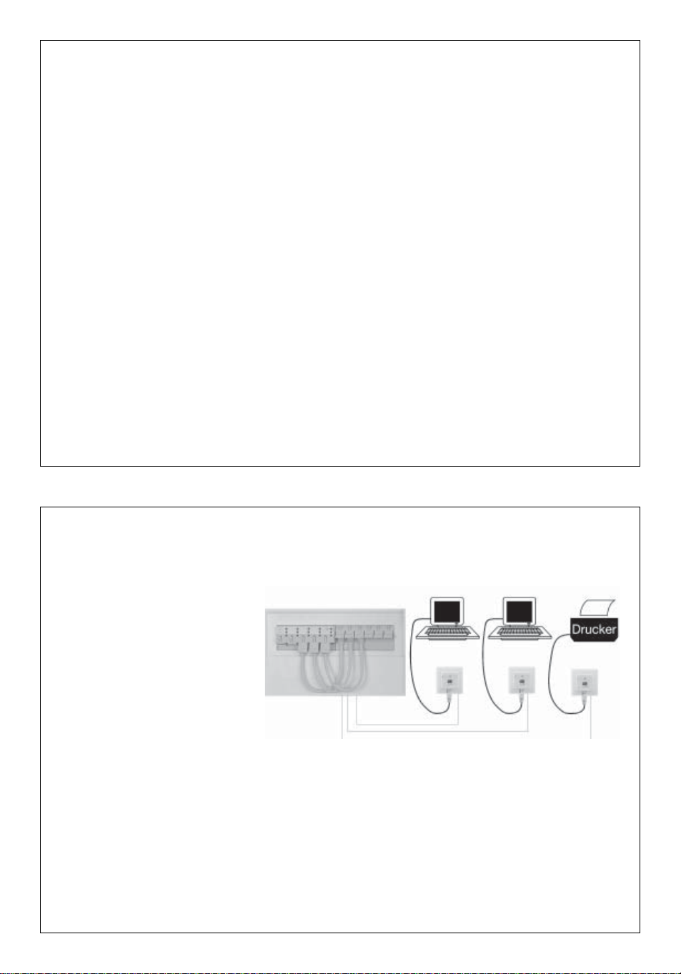
Anwendungsbeispiel
ne, Staubsauger, Radio usw.).
Verwenden Sie eigene Strom-
kreise, einen getrennten Über-
spannungsschutz (C-Ableiter) und
kennzeichnen Sie den Stromkreis
sowie zugehörige Steckdosen ein-
deutig z. B. mit „EDV“.
Bild 2
16
Technical Data
Measurements:
Weight:
Color:
Material:
Range of temperature
Operation:
Storage:
Protection class:
Insulation class:
6 TE (1 TE – 17 mm)
365 g
light grey, similiar RAL 7035
ABS
-5 °C to 45 °C
-25° C to 70° C
IP 20according to EN 60 529
II
Subject to technical alterations
6
Inbetriebnahme
Montage
Achtung: Arbeiten am
230 V-Netz dürfen nur
von autorisiertem
Elektrofachpersonal
ausgeführt
werden!
Lebensgefahr durch
elektrischen Strom.
Bei allen Montagear-
beiten schalten Sie zu-
nächst die Netzspan-
nung frei!
Beachten Sie die aktuell gültigen
Normen und Richtlinien, um die
allgemeinen Sicherheitsbestim-
mungen für Fernmeldeanlagen zu
erfüllen und um Störbeeinflus-
sungen zu vermeiden.
Achten Sie bei kombinierten Anla-
gen auf den Berührungsschutz
des Starkstromteils. Der Berüh-
rungsschutz muss auch dann ge-
währleistet sein, wenn Sie die ge-
meinsame Abdeckung entfernt
haben (dies ist bei Altanlagen
nicht immer gegeben).
Achten Sie bei der Errichtung
kombinierter Anlagen auf die Ein-
haltung der Mindestabstände von
10 mm zwischen Daten-/Fern-
meldeleitungen und Starkstromlei-
tungen.
Arbeiten an bestehenden Daten-
netzen bedürfen ggf. der Zustim-
mung der jeweiligen Netzwerk-/
Datenbeauftragten sowie einer
vorhergehenden Datensicherung.
Beachten Sie bitte auch die zu-
lässige Betriebstemperatur, set-
zen Sie das Patchpanel nicht di-
rekt neben Geräten mit hoher
Wärmeentwicklung (z. B. Dimmer)
ein.
Die Montage wird wie folgt ausge-
führt:
1 Rasten Sie das REG-Patch-
panel, 6 Port auf der Hut-
schiene ein.
2 Lösen Sie die Schrauben des
Gerätedeckels und nehmen
Sie ihn ab.
3 Nach der Installation (s. S. 7)
stecken Sie den Deckel wieder
auf und schrauben Sie ihn fest.
15
Terminal Assignment
Colorcode
Other colorcodes are possible according to the details of the cable-producers.
wercslanimreTwercslanimreT wercslanimreT wercslanimreTwercslanimreT 11
1
11 22
2
22 33
3
33 44
4
44 55
5
55 66
6
66 77
7
77 88
8
88
otgnidroccaedocroloCotgnidroccaedocroloC otgnidroccaedocroloC otgnidroccaedocroloCotgnidroccaedocroloC A-865-AIT/AIE /etihw neerg neerg/etihw egnaro eulb/etihw eulb egnaro/etihw nworb nworb
otgnidroccaedocroloCotgnidroccaedocroloC otgnidroccaedocroloC otgnidroccaedocroloCotgnidroccaedocroloC B-865-AIT/AIE /etihw egnaro egnaro/etihw neerg eulb/etihw eulb neerg/etihw nworb nworb
7
Installation
1 Legen Sie das vorbereitete,
fachgerecht abisolierte Daten-
kabel (s. S. 8) in die kombinier-
te Zugentlastungs- und
Schirmungsklemme ein und
schrauben Sie die Kabel-
schelle fest.
2 Legen Sie die Adern gemäß
der Farbcode-Kennzeichnung
(s. S. 9) an den Anschluss-
klemmen an.
3 Drücken Sie die Drähte mit
einem LSA-Plus-Anlege-
werkzeug in die Klemmen.
4 Nach Aufsetzen und Befesti-
gen des Deckels stecken Sie
die Patchkabel in die RJ-45-
Buchsen an der Frontseite und
stellen Sie die Verbindungen
zu den aktiven Netzwerk-
komponenten her (z. B. einem
Switch, s. Bild 3).
5 Zum Lösen der Patchkabel
aus den Buchsen drücken Sie
zunächst auf den Entriege-
lungsknopf oberhalb der ent-
sprechenden Buchse und zie-
hen dann den Stecker heraus
(s. Bild 4).
Bild 3 Bild 4
14
Cable Preparing
Cable with Wire Braid
Cable-Ø bigger than 6 mm
Cable with Wire FoilCable-Ø smaller than 6 mm
Shorten the wire foil and the
transparent polyester foil, if
provided, by the same length.
Push the wire braid back and cut
it all round in that way, that
approx. 10 mm look out of the
plastic outer sheat.
Bare the plastic outer sheat by
approx. 70 mm.
Draw the supplementary wire of
all cables to the plastic outer
sheat, wind it round the braid and
clamp it under the clip.
Supplementary Wire
For thin cables (under 6 mm Ø)
bare the plastic outer sheat by
approx. 60 mm. Push the braid
back over the sheat and cut it to
14 mm.
Cut the wire- and plastic foil so,
that approx. 10 mm look out of
the plastic outer sheat.
Handle the supplementary wire
as the wire braid.
Bare the plastic outer sheat by
approx. 70 mm.
70 mm 70 mm
10 mm
70 mm
10 mm
70 mm
< 6 mm
70mm
14 mm

8
Kabelvorbereitung
Kabel mit Geflechtschirm
Kabel-Ø größer 6 mm
Kabel mit FolienschirmKabel-Ø kleiner 6 mm
Kürzen Sie die Schirmfolie und
transparente Polyesterfolie, so
vorhanden, auf dieselbe Länge.
Schieben Sie das Schirmgeflecht
zurück und schneiden es rund-
herum so ab, dass ca. 10 mm
aus dem Kunststoffmantel her-
ausragen.
Isolieren Sie den Kunststoff-
mantel ca. 70 mm ab.
Ziehen Sie den Beilaufdraht bei
allen Kabeln bis zum Kunststoff-
mantel zurück, wickeln ihn um
das Geflecht und klemmen ihn
unter der Schelle fest.
Beilaufdraht
Bei dünneren Kabeln (unter 6 mm
Ø) isolieren Sie den Kunststoff-
mantel ca. 60 mm ab. Schieben
Sie das Geflecht über den Mantel
zurück und kürzen es auf 14 mm.
Schneiden Sie Schirm- und
Kunststofffolie so ab, dass ca.
10 mm aus dem Kunststoffmantel
herausragen.
Den Beilaufdraht handhaben Sie
wie beim Geflechtschirm.
Isolieren Sie den Kunststoff-
mantel ca. 70 mm ab.
70 mm 70 mm
10 mm
70 mm 10 mm
70 mm
< 6 mm
70mm
14 mm
13
Installation
1 Lay the prepared profession-
ally bared data cable (s. page
14) in the combined terminal
of strain relief and shielding
and screw the cable clamp
up.
2 Apply the cores to the con-
necting terminals according to
the labelled color code (s.
page 15).
3 Press the wires in the termi-
nals by using a suitable tool,
e.g. the connection tool AW2.
4 Plug the patch panel in the
RJ-45 jacks on the front face
and connect them with the ac-
tive network components (s.
fig. 6).
5 For the disconnection of the
patch panel from the termi-
nals press the release knob
above of the respective termi-
nal at first and then extract
the plug from the terminal (s.
fig. 7).
Fig. 6 Fig. 7
9
Anschlussbelegung
Farbcode
Andere Farbkennzeichnungen nach Angaben der Kabelhersteller möglich.
emmelkssulhcsnAemmelkssulhcsnA emmelkssulhcsnA emmelkssulhcsnAemmelkssulhcsnA 11
1
11 22
2
22 33
3
33 44
4
44 55
5
55 66
6
66 77
7
77 88
8
88
A-865-AIT/AIEhcanedocbraFA-865-AIT/AIEhcanedocbraF A-865-AIT/AIEhcanedocbraF A-865-AIT/AIEhcanedocbraFA-865-AIT/AIEhcanedocbraF /ßiew nürg nürg/ßiew egnaro ualb/ßiew ualb egnaro/ßiew nuarb nuarb
B-865-AIT/AIEhcanedocbraFB-865-AIT/AIEhcanedocbraF B-865-AIT/AIEhcanedocbraF B-865-AIT/AIEhcanedocbraFB-865-AIT/AIEhcanedocbraF /ßiew egnaro egnaro/ßiew nürg ualb/ßiew ualb nürg/ßiew nuarb nuarb
12
Putting into Operation
Mounting
Attention: Work on
the 230-V-supply may
only be carried out by
authorized electricians.
Danger for life! Dis-
connect the main volt-
age at first for all
mounting works.
Pay attention to the actual norms,
in order to fulfil the general safety
requirements for telecommunica-
tion systems and to avoid disturb-
ing interferences.
Pay attention to the shock-proof
protection of the heavy-current
part in combined plants. The
shock-proof protection must also
be guaranteed, when you have
removed the common covering
(this is not always given for old in-
stallations).
Take care that the minimum dis-
tance of 10 mm between data-/
telecommunica-tion cables and
heavy-current cables are strictly
observed during the erection of
combined plants.
Working in existing data networks
require - if necessary - the assent
of the respective person in charge
of network and data as well as a
preceding data security.
Please also observe the permit-
ted operating temperature, do not
place the Patch panel directly be-
side devices with high heat evolu-
tion (e.g. dimmer).
The mounting is carried out as fol-
lows:
1 Snap the DIN Rail-Patch
panel, 6 Port on the DIN rail.
2 Disconnect the screws from
the device’s lid and remove
the lid.
3 After installation put the lid on
and screw it on.
10
Technische Daten
Abmessungen:
Gewicht:
Farbe:
Material:
Temperaturbereich
Betrieb:
Lager:
Schutzart:
Schutzklasse:
6 TE (1 TE ~ 17 mm)
365 g
lichtgrau ähnlich RAL 7035
ABS
-5° C bis 45° C
-25° C bis 70° C
IP 20 nach EN 60 529
II
Technische Änderungen vorbehalten.
11
General
The DIN Rail-Patch panel, 6 Port
is a passive network component
of category 5e/Class D for the
networking of up to 6 terminal de-
vices.
The patch panel does not require
any operating elements for the
user or installer.
It is designed as DIN rail compo-
nent for the mounting in an elec-
trical distribution respectively on
the DIN rail of a distribution box.
In order to avoid an interference
of the network by disturbances/al-
terations in the range of the
230-V-installation please always
disconnect the power supply of
the active devices (e.g. SR5) of
those of other power consumer
(coffee machine, hover, radio
etc.). Use separate circuits, an
isolated overvoltage protection
(C-arrester) and label the circuit
as well as the belonging jacks
clearly with “EDP”.
Application Sample
Fig. 5

9
Anschlussbelegung
Farbcode
Andere Farbkennzeichnungen nach Angaben der Kabelhersteller möglich.
emmelkssulhcsnAemmelkssulhcsnA emmelkssulhcsnA emmelkssulhcsnAemmelkssulhcsnA 11
1
11 22
2
22 33
3
33 44
4
44 55
5
55 66
6
66 77
7
77 88
8
88
A-865-AIT/AIEhcanedocbraFA-865-AIT/AIEhcanedocbraF A-865-AIT/AIEhcanedocbraF A-865-AIT/AIEhcanedocbraFA-865-AIT/AIEhcanedocbraF /ßiew nürg nürg/ßiew egnaro ualb/ßiew ualb egnaro/ßiew nuarb nuarb
B-865-AIT/AIEhcanedocbraFB-865-AIT/AIEhcanedocbraF B-865-AIT/AIEhcanedocbraF B-865-AIT/AIEhcanedocbraFB-865-AIT/AIEhcanedocbraF /ßiew egnaro egnaro/ßiew nürg ualb/ßiew ualb nürg/ßiew nuarb nuarb
12
Putting into Operation
Mounting
Attention: Work on
the 230-V-supply may
only be carried out by
authorized electricians.
Danger for life! Dis-
connect the main volt-
age at first for all
mounting works.
Pay attention to the actual norms,
in order to fulfil the general safety
requirements for telecommunica-
tion systems and to avoid disturb-
ing interferences.
Pay attention to the shock-proof
protection of the heavy-current
part in combined plants. The
shock-proof protection must also
be guaranteed, when you have
removed the common covering
(this is not always given for old in-
stallations).
Take care that the minimum dis-
tance of 10 mm between data-/
telecommunica-tion cables and
heavy-current cables are strictly
observed during the erection of
combined plants.
Working in existing data networks
require - if necessary - the assent
of the respective person in charge
of network and data as well as a
preceding data security.
Please also observe the permit-
ted operating temperature, do not
place the Patch panel directly be-
side devices with high heat evolu-
tion (e.g. dimmer).
The mounting is carried out as fol-
lows:
1 Snap the DIN Rail-Patch
panel, 6 Port on the DIN rail.
2 Disconnect the screws from
the device’s lid and remove
the lid.
3 After installation put the lid on
and screw it on.
8
Kabelvorbereitung
Kabel mit Geflechtschirm
Kabel-Ø größer 6 mm
Kabel mit FolienschirmKabel-Ø kleiner 6 mm
Kürzen Sie die Schirmfolie und
transparente Polyesterfolie, so
vorhanden, auf dieselbe Länge.
Schieben Sie das Schirmgeflecht
zurück und schneiden es rund-
herum so ab, dass ca. 10 mm
aus dem Kunststoffmantel her-
ausragen.
Isolieren Sie den Kunststoff-
mantel ca. 70 mm ab.
Ziehen Sie den Beilaufdraht bei
allen Kabeln bis zum Kunststoff-
mantel zurück, wickeln ihn um
das Geflecht und klemmen ihn
unter der Schelle fest.
Beilaufdraht
Bei dünneren Kabeln (unter 6 mm
Ø) isolieren Sie den Kunststoff-
mantel ca. 60 mm ab. Schieben
Sie das Geflecht über den Mantel
zurück und kürzen es auf 14 mm.
Schneiden Sie Schirm- und
Kunststofffolie so ab, dass ca.
10 mm aus dem Kunststoffmantel
herausragen.
Den Beilaufdraht handhaben Sie
wie beim Geflechtschirm.
Isolieren Sie den Kunststoff-
mantel ca. 70 mm ab.
70 mm 70 mm
10 mm
70 mm 10 mm
70 mm
< 6 mm
70mm
14 mm
13
Installation
1 Lay the prepared profession-
ally bared data cable (s. page
14) in the combined terminal
of strain relief and shielding
and screw the cable clamp
up.
2 Apply the cores to the con-
necting terminals according to
the labelled color code (s.
page 15).
3 Press the wires in the termi-
nals by using a suitable tool,
e.g. the connection tool AW2.
4 Plug the patch panel in the
RJ-45 jacks on the front face
and connect them with the ac-
tive network components (s.
fig. 6).
5 For the disconnection of the
patch panel from the termi-
nals press the release knob
above of the respective termi-
nal at first and then extract
the plug from the terminal (s.
fig. 7).
Fig. 6 Fig. 7

7
Installation
1 Legen Sie das vorbereitete,
fachgerecht abisolierte Daten-
kabel (s. S. 8) in die kombinier-
te Zugentlastungs- und
Schirmungsklemme ein und
schrauben Sie die Kabel-
schelle fest.
2 Legen Sie die Adern gemäß
der Farbcode-Kennzeichnung
(s. S. 9) an den Anschluss-
klemmen an.
3 Drücken Sie die Drähte mit
einem LSA-Plus-Anlege-
werkzeug in die Klemmen.
4 Nach Aufsetzen und Befesti-
gen des Deckels stecken Sie
die Patchkabel in die RJ-45-
Buchsen an der Frontseite und
stellen Sie die Verbindungen
zu den aktiven Netzwerk-
komponenten her (z. B. einem
Switch, s. Bild 3).
5 Zum Lösen der Patchkabel
aus den Buchsen drücken Sie
zunächst auf den Entriege-
lungsknopf oberhalb der ent-
sprechenden Buchse und zie-
hen dann den Stecker heraus
(s. Bild 4).
Bild 3 Bild 4
14
Cable Preparing
Cable with Wire Braid
Cable-Ø bigger than 6 mm
Cable with Wire FoilCable-Ø smaller than 6 mm
Shorten the wire foil and the
transparent polyester foil, if
provided, by the same length.
Push the wire braid back and cut
it all round in that way, that
approx. 10 mm look out of the
plastic outer sheat.
Bare the plastic outer sheat by
approx. 70 mm.
Draw the supplementary wire of
all cables to the plastic outer
sheat, wind it round the braid and
clamp it under the clip.
Supplementary Wire
For thin cables (under 6 mm Ø)
bare the plastic outer sheat by
approx. 60 mm. Push the braid
back over the sheat and cut it to
14 mm.
Cut the wire- and plastic foil so,
that approx. 10 mm look out of
the plastic outer sheat.
Handle the supplementary wire
as the wire braid.
Bare the plastic outer sheat by
approx. 70 mm.
70 mm 70 mm
10 mm
70 mm
10 mm
70 mm
< 6 mm
70mm
14 mm
6
Inbetriebnahme
Montage
Achtung: Arbeiten am
230 V-Netz dürfen nur
von autorisiertem
Elektrofachpersonal
ausgeführt
werden!
Lebensgefahr durch
elektrischen Strom.
Bei allen Montagear-
beiten schalten Sie zu-
nächst die Netzspan-
nung frei!
Beachten Sie die aktuell gültigen
Normen und Richtlinien, um die
allgemeinen Sicherheitsbestim-
mungen für Fernmeldeanlagen zu
erfüllen und um Störbeeinflus-
sungen zu vermeiden.
Achten Sie bei kombinierten Anla-
gen auf den Berührungsschutz
des Starkstromteils. Der Berüh-
rungsschutz muss auch dann ge-
währleistet sein, wenn Sie die ge-
meinsame Abdeckung entfernt
haben (dies ist bei Altanlagen
nicht immer gegeben).
Achten Sie bei der Errichtung
kombinierter Anlagen auf die Ein-
haltung der Mindestabstände von
10 mm zwischen Daten-/Fern-
meldeleitungen und Starkstromlei-
tungen.
Arbeiten an bestehenden Daten-
netzen bedürfen ggf. der Zustim-
mung der jeweiligen Netzwerk-/
Datenbeauftragten sowie einer
vorhergehenden Datensicherung.
Beachten Sie bitte auch die zu-
lässige Betriebstemperatur, set-
zen Sie das Patchpanel nicht di-
rekt neben Geräten mit hoher
Wärmeentwicklung (z. B. Dimmer)
ein.
Die Montage wird wie folgt ausge-
führt:
1 Rasten Sie das REG-Patch-
panel, 6 Port auf der Hut-
schiene ein.
2 Lösen Sie die Schrauben des
Gerätedeckels und nehmen
Sie ihn ab.
3 Nach der Installation (s. S. 7)
stecken Sie den Deckel wieder
auf und schrauben Sie ihn fest.
15
Terminal Assignment
Colorcode
Other colorcodes are possible according to the details of the cable-producers.
wercslanimreTwercslanimreT wercslanimreT wercslanimreTwercslanimreT 11
1
11 22
2
22 33
3
33 44
4
44 55
5
55 66
6
66 77
7
77 88
8
88
otgnidroccaedocroloCotgnidroccaedocroloC otgnidroccaedocroloC otgnidroccaedocroloCotgnidroccaedocroloC A-865-AIT/AIE /etihw neerg neerg/etihw egnaro eulb/etihw eulb egnaro/etihw nworb nworb
otgnidroccaedocroloCotgnidroccaedocroloC otgnidroccaedocroloC otgnidroccaedocroloCotgnidroccaedocroloC B-865-AIT/AIE /etihw egnaro egnaro/etihw neerg eulb/etihw eulb neerg/etihw nworb nworb

5
Allgemeines
Das REG-Patchpanel, 6 Port ist
eine passive Netzwerkkompo-
nente entsprechend Category 5e/
Class D zur Verkabelung von bis
zu 6 Endgeräten.
Das Patchpanel benötigt keinerlei
Bedienelemente für den Benutzer
oder Installateur.
Es ist als Reiheneinbaugerät
(REG) für die Montage in der
Elektroverteilung bzw. auf der
Hutschiene eines Verteilerkastens
(KVK) vorgesehen.
Um eine Beeinflussung des Netz-
werkes durch Störungen/Verände-
rungen im Bereich der 230-V-In-
stallation zu vermeiden, trennen
Sie bitte stets die Spannungs-
versorgung der aktiven Geräte
sowie der Datenendgeräte (PC
usw.) (z. B. SR5) von denen an-
derer Verbraucher (Kaffeemaschi-
Anwendungsbeispiel
ne, Staubsauger, Radio usw.).
Verwenden Sie eigene Strom-
kreise, einen getrennten Über-
spannungsschutz (C-Ableiter) und
kennzeichnen Sie den Stromkreis
sowie zugehörige Steckdosen ein-
deutig z. B. mit „EDV“.
Bild 2
16
Technical Data
Measurements:
Weight:
Color:
Material:
Range of temperature
Operation:
Storage:
Protection class:
Insulation class:
6 TE (1 TE – 17 mm)
365 g
light grey, similiar RAL 7035
ABS
-5 °C to 45 °C
-25° C to 70° C
IP 20according to EN 60 529
II
Subject to technical alterations
Patch-Panel REG/6-fach
Gebrauchsanweisung
Operating Instructions
© 2002 293 457 Stand 10.02 Gedruckt auf 100 % chlorfrei gebleichtem Papier
BeiWarenrücksendungen auf Grund von
Beanstandungen wenden Sie sich bitte an unser
Service Center:
Merten GmbH & Co.KG, Systemlösungen für die
Elektrotechnik, Service Center
Fritz-Kotz-Straße8, Industriegebiet Bomig-West
D-51674Wiehl
Telefon:+49 (0) 22 61/702-204
Telefax:+49 (0) 22 61/702-136
E-Mail:servicecenter@merten.de
Internet:www.merten.de
Bei technischen Fragen wenden Sie sich bitte an
unsere InfoLine:
Telefon:01 805/21 25 81 oder 0 800/63 78 36 40
Telefax:01 805/21 25 82 oder 0 800/63 78 36 30
E-Mail:[email protected]
Table of contents
Languages:
Other merten Switch manuals


Popular Switch manuals by other brands


Symbol
Symbol WS 2000 System reference

Brocade Communications Systems
Brocade Communications Systems VDX 8770-4 quick start guide

Alcatel-Lucent
Alcatel-Lucent 1830 PSS-16 Maintenance and trouble-clearing user guide

ORiNG
ORiNG IGS-9084GP Quick installation guide

ZyXEL Communications
ZyXEL Communications XS3800-28 user guide

pro bel
pro bel Freeway Series user guide