manuals.online logo
Brands
  1. Home
  2. •
  3. Brands
  4. •
  5. iNels
  6. •
  7. Switch
  8. •
  9. iNels RFSAI-11B-SL User manual

iNels RFSAI-11B-SL User manual

02-53/2021 Rev.0
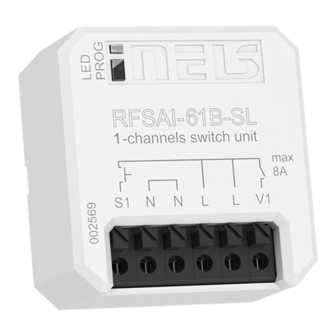
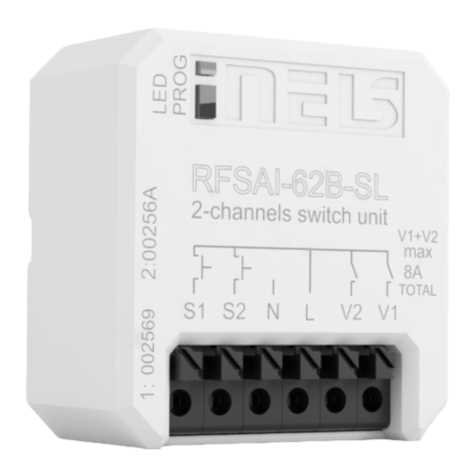
RFSAI-62B-SL, RFSAI-61B-SL, RFSAI-11B-SL
Dual Band wireless switching component input button
EN
Made in Czech Republic
Characteristics /
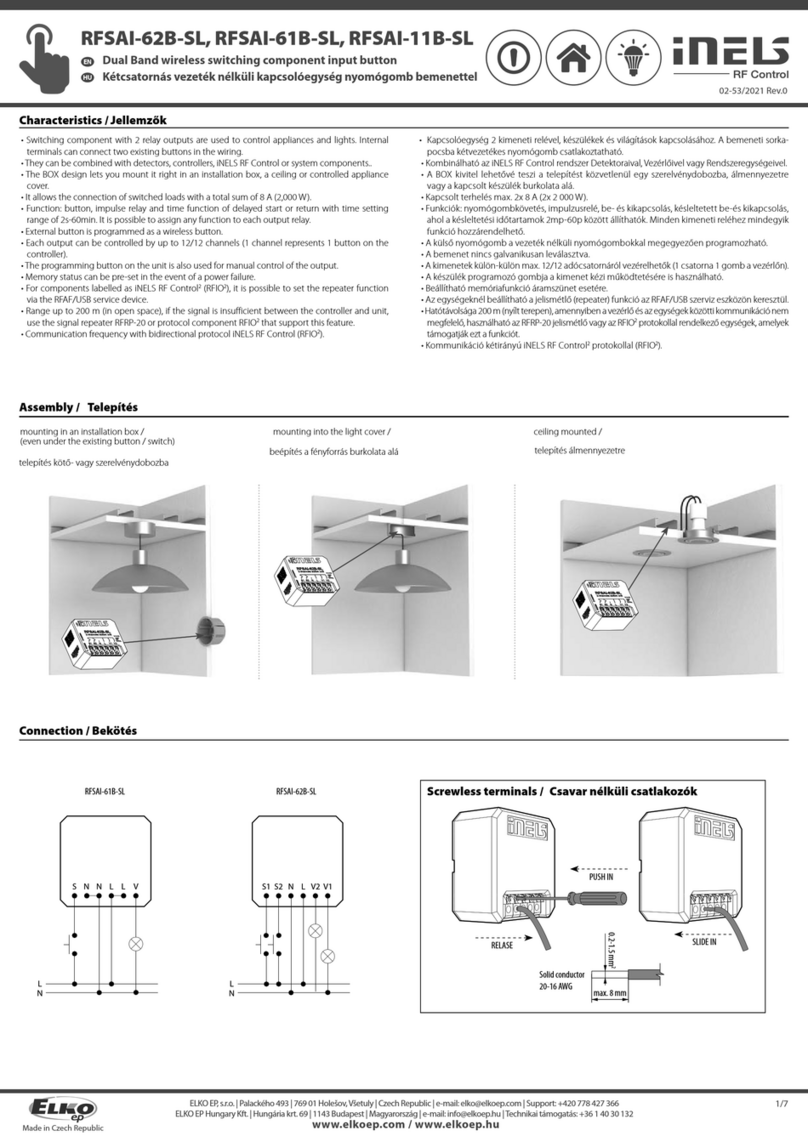
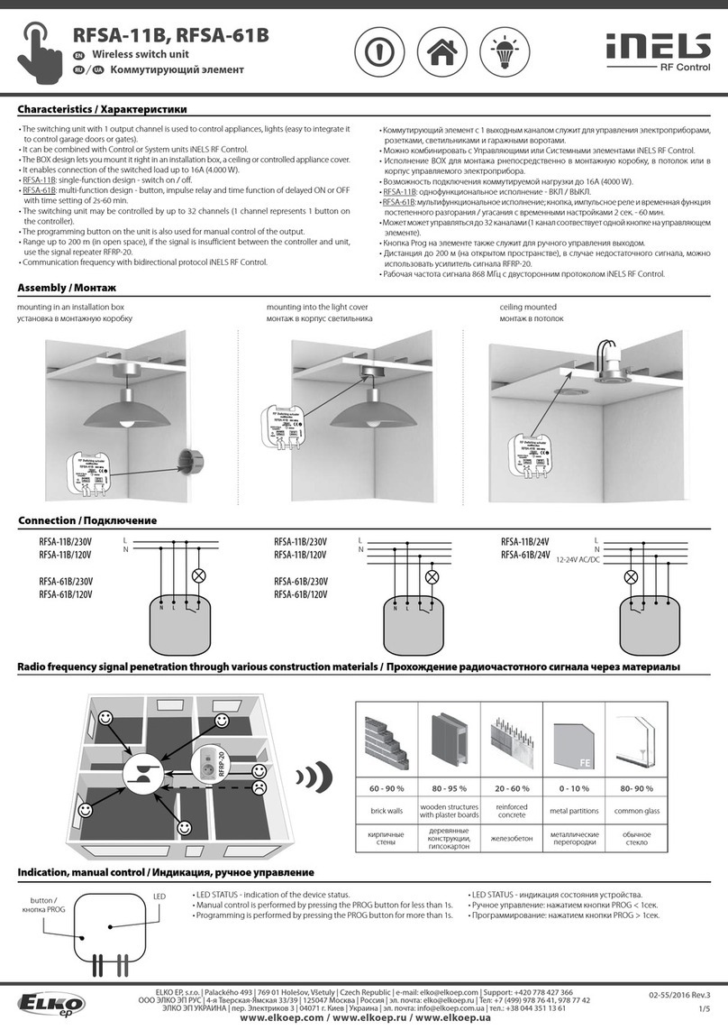
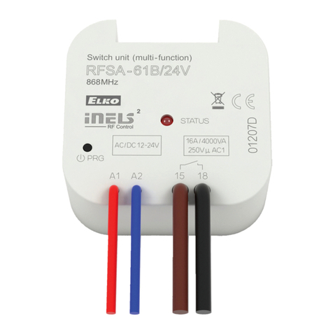
• Switching component with 2 relay outputs are used to control appliances and lights. Internal
terminals can connect two existing buttons in the wiring.
• They can be combined with detectors, controllers, iNELS RF Control or system components..
• The BOX design lets you mount it right in an installation box, a ceiling or controlled appliance
cover.
• It allows the connection of switched loads with a total sum of 8 A (2,000 W).
• Function: button, impulse relay and time function of delayed start or return with time setting
range of 2s-60min. It is possible to assign any function to each output relay.
• External button is programmed as a wireless button.
• Each output can be controlled by up to 12/12 channels (1 channel represents 1 button on the
controller).
• The programming button on the unit is also used for manual control of the output.
• Memory status can be pre-set in the event of a power failure.
• For components labelled as iNELS RF Control2(RFIO2), it is possible to set the repeater function
via the RFAF/USB service device.
• Range up to 200 m (in open space), if the signal is insufficient between the controller and unit,
use the signal repeater RFRP-20 or protocol component RFIO2that support this feature.
• Communication frequency with bidirectional protocol iNELS RF Control (RFIO2).
Assembly /
Connection /
Screwless terminals /
mounting in an installation box /
(even under the existing button / switch) mounting into the light cover / ceiling mounted /
1/7
RFSAI-62B-SLRFSAI-61B-SL
Solid conductor
SLIDE IN
PUSH IN
RELASE
20-16 AWG
0.2-1.5 mm2
max. 8 mm
DE
Funk-Schaltaktor mit zwei Kanälen und Tasteneingang
www.elkoep.com / www.elkoep.de
ELKO EP, s.r.o. | Palackého 493 | 769 01 Holešov, Všetuly | Czech Republic | e-mail: [email protected] | Support: +420 778 427 366
ELKO EP Germany GmbH | Minoritenstr. 7 | 50667 Köln | Deutschland | E-mail: [email protected] | Tel: +49 (0) 221 222 837 80
Eigenschaften
• Schaltaktor mit 2 Ausgangsrelais dient zur Steuerung von El. Geräten und Beleuchten. Sie können
2 vorhandene Tasten in der Verdrahtung an die internen Klemmen anschließen.
• Kann mit Detektoren, Sender oder Aktoren iNELS RF Control.
• Das BOX-Modul-Design des Gerätes ermöglicht den Einbau in einer Schalterdose, einer Geräte-
abdeckung oder in der Decke.
• Er ermöglicht den Anschluss von Schaltlasten mit einer Gesamtsumme von 8 A (2.000 W).
• Funktion: Taste, Stromstoßrelais und Zeitfunktion von verzögerter Start oder zurückkehren mit
einem Einstellbereich von 2s-60 Min. Jedem Ausgangsrelais kann eine Funktion zugewiesen
werden.
• Die Programmiertaste am Gerät wird auch für die manuelle Steuerung des Ausgangs verwendet.
• Der Eingang ist nicht galvanisch isoliert.
• Jeder Ausgang kann bis zu 12/12 Kanäle gesteuert werden (1 Kanal repräsentiert 1 Taste auf der
Steuerung).
• Der Speicherstatus kann bei einem Stromausfall eingestellt werden.
• Für Aktoren, die als iNELS RF Control2(RFIO2) gekennzeichnet sind, ist es möglich, die Repeater-
funktion über das RFAF/USB Servicegerät einzustellen.
• Reichweite bis zu 200 m (im Freien), verwenden Sie einen RFRP-20-Signal-Repeater oder die Aktoren
mit den RFIO2-Funktionen, wenn das Signal zwischen dem Sender und dem Aktor nicht ausreicht ist.
• Kommunikationsfrequenz mit bidirektionalem Protokoll iNELS RF Control2(RFIO2).
Installation
Verbindung
Installation in einer Einbaudose
(auch unter einem existierenden Taster / Schalter)
Installation unter einer Lichtabdeckung Installation in der Decke
Schraubenlose Klemmen
02-53/2021 Rev.0
RFSAI-62B-SL, RFSAI-61B-SL, RFSAI-11B-SL
Dual Band wireless switching component input button
EN
Made in Czech Republic
x
RFRP-20
Radio frequency signal penetration through various construction materials /
60 - 90 % 80 - 95 % 20 - 60 % 0 - 10 % 80- 90 %
brick walls wooden structures
with plaster boards reinforced
concrete metal partitions common glass
Indication, manual control /
1. LED / PROG button
• LED green V1 - device status indication for output 1
• LED red V2 - device status indication for output 2.
Indicators of memory function:
On - LED blinks x 3.
Off - The LED lights up once for a long time.
• Manual control is performed by pressing the PROG
button for<1s.
• Programming is performed by pressing the PROG button
for 3-5s.
2. Terminal block - connection for external button
3. Terminal block - connecting the neutral conductor
4. Terminal block - load connection with the sum of the total current 8A
(eg V1=6A, V2=2A)
5. Terminal block for connecting the phase conductor
In the programming and operating mode, the LED on the
component lights up at the same time each time the button is
pressed - this indicates the incoming command.
* RFSAI-61B-SL: one output contact, status indication by red LED
Compatibility /
The device can be combined with all system components, controls and devices
of iNELS RF Control and iNELS RF Control2.
The detector can be assigned an iNELS RF Control2(RFIO2) communication pro-
tocol.
Channel selection /
Channel selection (RFSAI-62B-SL) is done by pressing the PROG buttons for 1-3s.
RFSAI-61B-SL: press for more than 1 second.
After button release, LED is flashing indicating the output channel: red (1) or
green (2). All other signals are indicated by corresponding color of LED for each
channel.
2/7
PROG <3s1 x

1
2
3
4
5
Use a suitable tool (pa-
per clip, screwdriver)
to push on the control
pin. The batteries
are raised and the
programming button is
released.
After removing
the control flaps,
the programming
button is accessible.
The programming
button is operated
with a suitable thin
tool.
DE
Funk-Schaltaktor mit zwei Kanälen und Tasteneingang
www.elkoep.com / www.elkoep.de
ELKO EP, s.r.o. | Palackého 493 | 769 01 Holešov, Všetuly | Czech Republic | e-mail: [email protected] | Support: +420 778 427 366
ELKO EP Germany GmbH | Minoritenstr. 7 | 50667 Köln | Deutschland | E-mail: [email protected] | Tel: +49 (0) 221 222 837 80
Radiofrequenzsignal dringt durch verschiedene Baumaterialien
Ziegelwände Holzkonstruktionen
mit
Gipskartonplatten
Stahlbeton Metallwände Glas
Weitere Angaben finden Sie hier: “Installation manual iNELS RF Control”:
http://www.elkoep.com/catalogs-and-brochures
Anzeige, manuelle Steuerung
Kompatibilität
Aktor kann mit allen Systemelementen, Bedienelementen und Elementen von
iNELS RF Control und iNELS RF Control2kombiniert werden.
Zum Aktor kann ein Detektor mit Kommunikationsprotokoll iNELS RF Control2
(RFIO2) zugeordnet werden.
Auswahl des Kanals
Durch Drücken der PROG Taste für 1-3s wird der Kanal ausgewählt.
RFSAI-11B-SL: länger als 1 Sekunde drücken.
Nach loslassen der Taste, LED blinkt und zeigt des Ausgangskanal an: rot (1) oder
grün (2). Alle anderen Signale werden durch entsprechende Farbe der LED für
jeden Kanal angezeigt.
1. LED / Taste PROG
• LED grün V1 - Gerätestatusanzeige für Ausgang 1.
• LED rot V2 - Gerätestatusanzeige für Ausgang 2.
Anzeige der Speicherfunktion:
Ein - LED blinkt 3x.
Aus - die LED leuchtet einmal lang.
• Manuelle Steuerung wird durch Drücken der PROG-Taste
weniger als 1s aktiviert.
• Programmierung wird durch Drücken der PROG-Taste
länger als 3-5s aktiviert.
2. Klemmenleiste - für externe Schalter.
3. Klemmblock zum Anschluss des Neutralleiters
4. Klemmblock für Lastanschluss mit der Summe des Gesamtstroms
8A (zB V1 = 6A, V2 = 2A)
5. Klemmblock zum Anschluss des Phasenleiters
Im Programmier- und Löschenmodus leuchtet die LED am
Aktor bei jedem Tastendruck gleichzeitig auf - dies zeigt den
eingehenden Befehl an.
*RFSAI-11B-SL: ein Ausgangskontakt, Statusanzeige durch rote LED
Drücken Sie mit einem geeigne-
ten Werkzeug (Büroklammer,
Schraubendreher) auf den Ste-
uerstift. Die Batterien werden
angehoben und die Program-
miertaste wird losgelassen.
Nach Entfernen der
Bedienklappen ist
die Programmier-
taste zugänglich.
Der Programmier-
taster wird mit
einem geeigneten
dünnen Werkzeug
bedient.
02-53/2021 Rev.0
RFSAI-62B-SL, RFSAI-61B-SL, RFSAI-11B-SL
Dual Band wireless switching component input button
EN
Made in Czech Republic

1 x

1 x
Functions and programming with RF transmitters /
Function button /
Description of button /
The output contact will be closed by pressing the button and opened by releasing
the button.
For the correct execution of individual commands (press = closing / releasing the
button = opening), the time delay between these commands must be a min of .
1s (press - delay 1s - release).
Programming /
Press of programming button
on receiver RFSAI-62B for 3-5 s
(RFSAI-61B-SL: press for more than
1 s) will activate receiver RFSAI-62B
into programming mode. LED is
flashing in 1s interval.
Press of programming button on
receiver RFSAI-62B for 3-5 s (RF-
SAI-11B-SL: press for more than 1s)
will activate receiver RFSAI-62B
into programming mode. LED is
flashing in 1s interval.
Press of programming button on
receiver RFSAI-62B for 3-5 s (RF-
SAI-61B-SL: press for more than 1
s) will activate receiver RFSAI-62B
into programming mode. LED is
flashing in 1s interval.
Select and press one button
on wireless switch, to this but-
ton will be assigned function
Button.
Press of programming button
on receiver RFSAI-62B shorter
then 1 second will finish pro-
gramming mode. The LED
lights up according to the pre-
set memory function.
Function switch on /
Description of switch on /
The output contact will be closed by pressing the button.
Programming /
Two presses of your selected
button on the RF transmitter
assigns the function switch on
(must be a lapse of 1s between
individual presses).
Press of programming button
on receiver RFSAI-62B shorter
then 1 second will finish pro-
gramming mode. The LED
lights up according to the pre-
set memory function.
3/7

1 x
Function switch off /
Description of switch o /
The output contact will be opened by pressing the button.
Programming /
Three presses of your selected
button on the RF transmitter
assigns the function switch off
(must be a lapse of 1s between
individual presses).
Press of programming button
on receiver RFSAI-62B shorter
then 1 second will finish pro-
gramming mode. The LED
lights up according to the pre-
set memory function.
2

1 x
2

2 x
2

3 x
PROG <1s1 x
3
PROG <1s1 x
3
1
PROG <5s1 x
3
PROG <1s1 x
1
PROG <5s1 x
1
PROG <5s1 x






DE
Funk-Schaltaktor mit zwei Kanälen und Tasteneingang
www.elkoep.com / www.elkoep.de
ELKO EP, s.r.o. | Palackého 493 | 769 01 Holešov, Všetuly | Czech Republic | e-mail: [email protected] | Support: +420 778 427 366
ELKO EP Germany GmbH | Minoritenstr. 7 | 50667 Köln | Deutschland | E-mail: [email protected] | Tel: +49 (0) 221 222 837 80
Funktionen und Programmierung mit RF-Sendern
Funktionstaste
Beschreibung der Schaltäche
Der Ausgangskontakt wird durch Drücken der Taste geschlossen und durch Los-
lassen der Taste geöffnet werden.
Für die korrekte Ausführung einzelner Befehle (drücken = Schließen / Loslassen
der Taste = Öffnen) muss die Zeitverzögerung zwischen diesen Befehlen min. 1s
(Drücken - Verzögerung 1s - Loslassen).
Programmierung
Drücken der Programmiertaste
am Empfänger RFSAI-62B für
3 - 5 Sekunden (RFSAI-11B-SL:
länger als 1 Sekunde drücken)
aktiviert den Programmiermo-
dus des Empfängers RFSAI-62B.
LED blinkt im 1s-Intervall.
Wählen Sie und drücken Sie
eine Taste am funkgesteuerten-
Schalter, dieser Taste wird die
Funktion zugeordnet. Drücken der Programmiertas-
te am Empfänger RFSAI-62B,
kürzer als 1 Sekunde, der Pro-
grammiermodus wird been-
det, LED Leuchtet nach der
eingestellten Funktion.
Funktionsschalter EIN
Beschreibung Schalter EIN
Der Ausgangskontakt wird durch Drücken der Taste geschlossen.
Programmierung
Drücken der Programmiertaste
am Empfänger RFSAI-62B für
3 - 5 Sekunden (RFSAI-11B-SL:
länger als 1 Sekunde drücken)
aktiviert den Programmiermo-
dus des Empfängers RFSAI-62B
LED blinkt im 1s-Intervall.
Zwei x Drücken der von Ihnen
gewählten Taste auf dem RF-
Sender weist die Funktion Schal-
ter EIN zu (es muss eine Pause
von 1s zwischen den einzelnen
Tastenbetätigungen eingehal-
ten werden).
Drücken der Programmiertas-
te am Empfänger RFSAI-62B
kürzer als 1 Sekunde beendet
den Programmiermodus, LED
Leuchtet nach der eingestell-
ten Funktion.
Funktionsschalter AUS
Beschreibung Schalter AUS
Der Ausgangskontakt wird durch Drücken der Taste geöffnet.
Programmierung
Drücken der Programmiertaste
am Empfänger RFSAI-62B für
3 - 5 Sekunden (RFSAI-11B-SL:
länger als 1 Sekunde drücken)
aktiviert den Programmiermo-
dus des Empfängers RFSAI-62B
LED blinkt im 1s-Intervall.
Drei x Drücken der von Ihnen
gewählten Taste auf dem RF-
Sender weist die Funktion Schal-
ter AUS zu (es muss eine Pause
von 1s zwischen den einzelnen
Tastenbetätigungen eingehal-
ten werden).
Drücken der Programmiertas-
te am Empfänger RFSAI-62B,
kürzer als 1 Sekunde beendet
den Programmiermodus, LED
Leuchtet nach der eingestell-
ten Funktion.
02-53/2021 Rev.0
RFSAI-62B-SL, RFSAI-61B-SL, RFSAI-11B-SL
Dual Band wireless switching component input button
EN
Made in Czech Republic

1 x

1 x
Function impulse relay /
Description of impulse relay /
The output contact will be switched to the opposite position by each press of the
button. If the contact was closed, it will be opened and vice versa.
Programming /
Four presses of your selected
button on the RF transmitter as-
signs the function impulse relay
(must be a lapse of 1s between
individual presses).
Press of programming button
on receiver RFSAI-62B shorter
then 1 second will finish pro-
gramming mode. The LED
lights up according to the pre-
set memory function.
Funcion delayed off /
Description of delayed o /
The output contact will be closed by pressing the button and opened after the set
time interval has elapsed.
Programming /
Assignment of the delayed off
function is performed by five
presses of the selected button
on the RF transmitter (must be
a lapse of 1s between individual
presses).
Press of programming button
longer then 5 seconds, will
activate actuator into timing
mode. LED flashs 2x in each
1s interval. Upon releasing the
button, the delayed return
time starts counting.
4/7
t = 2s . . . 60min.

After the desired time has
elapsed (range of 2s...60min),
the timing mode ends by
pressing the button on the
RF transmitter, to which the
delayed return function is
assigned. This stores the set
time interval into the actuator
memory.
Press of programming button
on receiver RFSAI-62B shorter
then 1 second will finish pro-
gramming mode. The LED lights
up according to the pre-set
memory function.
2

4 x
2

5 x
4

1 x
PROG <1s1 x
31
PROG <5s1 x

1
PROG <5s1 x
1
PROG <5s1 x


3
PROG > 5s1 x

5
PROG <1s1 x PROG <1 x

Press of programming button
on receiver RFSAI-62B for 3-5 s
(RFSAI-61B-SL: press for more than
1 s) will activate receiver RFSAI-62B
into programming mode. LED is
flashing in 1s interval.
Press of programming button on
receiver RFSAI-62B for 3-5 s (RF-
SAI-61B-SL: press for more than 1
s) will activate receiver RFSAI-62B
into programming mode. LED is
flashing in 1s interval.
DE
Funk-Schaltaktor mit zwei Kanälen und Tasteneingang
www.elkoep.com / www.elkoep.de
ELKO EP, s.r.o. | Palackého 493 | 769 01 Holešov, Všetuly | Czech Republic | e-mail: [email protected] | Support: +420 778 427 366
ELKO EP Germany GmbH | Minoritenstr. 7 | 50667 Köln | Deutschland | E-mail: [email protected] | Tel: +49 (0) 221 222 837 80
Funktion Stromstoßrelais
Beschreibung Schalter
Der Ausgangskontakt wird auf die entgegengesetzte Position bei jedem Drücken
der Taste umgeschaltet werden. Wenn der Kontakt geschlossen war, wird es geöff-
net werden und umgekehrt.
Programmierung
Drücken der Programmiertaste
am Empfänger RFSAI-62B für
3 - 5 Sekunden (RFSAI-11B-SL:
länger als 1 Sekunde drücken)
aktiviert den Programmiermo-
dus des Empfängers RFSAI-62B
LED blinkt im 1s-Intervall.
Vier x Drücken der von Ihnen
gewählten Taste auf dem RF-
Sender weist die Funktion Im-
pulsrelais zu (es muss eine Pause
von 1s zwischen den einzelnen
Tastenbetätigungen eingehal-
ten werden).
Drücken der Programmiertas-
te am Empfänger RFSAI-62B,
kürzer als 1 Sekunde beendet
den Programmiermodus, LED
Leuchtet nach der eingestell-
ten Funktion.
Funktion Verzögerung AUS
Beschreibung Verzögerung AUS
Der Ausgangskontakt wird durch Drücken der Taste geschlossen und geöffnet,
nachdem das eingestellte Zeitintervall abgelaufen ist.
Drücken der Programmiertas-
te am Empfänger RFSAI-62B
für 3 - 5 Sekunden (RFSAI-11B-
SL: länger als 1 Sekunde drü-
cken) aktiviert den Program-
miermodus des Empfängers
RFSAI-62B LED blinkt im 1s-
Intervall.
Zuweisung des verzögerten
Ausschaltfunktion wird durch
fünf x Drücken der ausgewähl-
ten Taste auf dem RF-Sender
durchgeführt (es muss eine
Pause von 1s zwischen den
einzelnen Tastenbetätigungen
eingehalten werden).
Drücken der Programmiertas-
te länger als 5 Sekunden akti-
viert den Zeiteinstell-Modus.
LED-blinkt 2x je 1s-Intervall.
Nach dem Loslassen der Taste
beginnt die verzögerte Rück-
laufzeit zu zählen.
Programmierung
Nachdem die gewünschte
Zeit abgelaufen ist (Bereich
von 2s...60min), endet der
Zeiteinstell-Modus durch Drü-
cken der Taste auf dem RF-
Sender, dem die verzögerte
Rückstellfunktion zugeordnet
ist. Dieser speichert das ein-
gestellte Zeitintervall in dem
Speicher des Aktors.
Drücken der Programmiertaste
am Empfänger RFSAI-62B kürzer
als 1 Sekunde beendet den Pro-
grammiermodus, LED Leuchtet
nach der eingestellten Funktion.
02-53/2021 Rev.0
RFSAI-62B-SL, RFSAI-61B-SL, RFSAI-11B-SL
Dual Band wireless switching component input button
EN
Made in Czech Republic

1 x
t = 2s . . . 60min.

Function delayed on /
Description of delayed on /
The output contact will be opened by pressing the button and closed after the set
time interval has elapsed.
Programming /
Assignment of the delayed on
function is performed by six
presses of the selected button
on the RF transmitter (must be
a lapse of 1s between individual
presses).
Press of programming button
longer then 5 seconds, will
activate actuator into timing
mode. LED flashs 2x in each
1s interval. Upon releasing the
button, the delayed return
time starts counting.
After the desired time has
elapsed (range of 2s...60min),
the timing mode ends by
pressing the button on the
RF transmitter, to which the
delayed return function is
assigned. This stores the set
time interval into the actuator
memory.
Press of programming button
on receiver RFSAI-62B shorter
then 1 second will finish pro-
gramming mode. The LED lights
up according to the pre-set
memory function.
Programming with RF control units /
5/7
Addresses listed on the front side of the actuator are used for programming
and controlling the actuator and individual RF channels by control units.
addresses for
individual relays
(channels) /
2

6 x
4

1 x
1
PROG <5s1 x
1
PROG <5s1 x

3
PROG <5s1 x

5
PROG <1s1 x PROG <1 x

Press of programming button on
receiver RFSAI-62B for 3-5 s (RF-
SAI-61B-SL: press for more than
1s) will activate receiver RFSAI-
62B into programming mode.
LED is flashing in 1s interval.
DE
Funk-Schaltaktor mit zwei Kanälen und Tasteneingang
www.elkoep.com / www.elkoep.de
ELKO EP, s.r.o. | Palackého 493 | 769 01 Holešov, Všetuly | Czech Republic | e-mail: [email protected] | Support: +420 778 427 366
ELKO EP Germany GmbH | Minoritenstr. 7 | 50667 Köln | Deutschland | E-mail: [email protected] | Tel: +49 (0) 221 222 837 80
Funktion Verzögerung EIN
Beschreibung Verzögerung EIN
Der Ausgangskontakt wird durch Drücken der Taste geöffnet und geschlossen,
nachdem das eingestellte Zeitintervall abgelaufen ist.
Programmierung
Drücken der Programmiertas-
te am Empfänger RFSAI-62B
für 3 - 5 Sekunden (RFSAI-11B-
SL: länger als 1 Sekunde drü-
cken) aktiviert den Program-
miermodus des Empfängers
RFSAI-62B LED blinkt im 1s-
Intervall.
Zuweisung des verzögerten
Ausschaltfunktion wird durch
sechs x Drücken der ausgewähl-
ten Taste auf dem RF-Sender
durchgeführt (es muss eine
Pause von 1s zwischen den
einzelnen Tastenbetätigungen
eingehalten werden).
Drücken der Programmiertaste
länger als 5 Sekunden akti-
viert den Zeiteinstell-Modus.
LED-blinkt 2x je 1s-Intervall.
Nach dem Loslassen der Taste
beginnt die verzögerte Rück-
laufzeit zu zählen.
Nachdem die gewünschte
Zeit abgelaufen ist (Bereich
von 2s...60min), endet der
Zeiteinstell-Modus durch Drü-
cken der Taste auf dem RF-
Sender, dem die verzögerte
Rückstellfunktion zugeordnet
ist. Dieser speichert das ein-
gestellte Zeitintervall in dem
Speicher des Aktors.
Drücken der Programmiertaste
am Empfänger RFSAI-62B kürzer
als 1 Sekunde beendet den Pro-
grammiermodus, LED Leuchtet
nach der eingestellten Funktion.
Programmieren mit RF-Steuereinheiten
Die Adresse auf der Vorderseite wird zur Programmierung und Steuerung-
des Aktors, sowie individueller RF Kanäle von / durch RF-Steuereinheiten
verwendet.
Adressen für
einzelne Relais
(Kanäle)
02-53/2021 Rev.0
RFSAI-62B-SL, RFSAI-61B-SL, RFSAI-11B-SL
Dual Band wireless switching component input button
EN
Made in Czech Republic
Delete actuator /
Deleting one position of the transmitter /
By pressing the programming button on the actuator for 8 sec-
onds (RFSAI-61B-SL: press for 5 second), deletion of one transmitter
activates. LED flashs 4x in each 1s interval.
Pressing the required button on the transmitter deletes it from
the actuator's memory.
To confirm deletion, the LED will confirm with a flash long and
the component returns to the operating mode. The memory
status is not indicated.
Deletion does not affect the pre-set memory function.
Deleting the entire memory /
By pressing the programming button on the actuator for 11 sec-
onds (RFSAI-61B-SL: press for more than 8 second), deletion occurs
of the actuator's entire memory. LED flashs 4x in each 1s interval.
The actuator goes into the programming mode, the LED flashes
in 0.5s intervals (max. 4 min.).
You can return to the operating mode by pressing the Prog button
for less than 1s. The LED lights up according to the pre-set memory
function and the component returns to the operating mode.
Deletion does not affect the pre-set memory function.
Selecting the memory function /
• Memory function on:
- For functions 1-4, these are used to store the last state of the relay output before the supply
voltage drops, the change of state of the output to the memory is recorded 15 seconds after
the change.
- For functions 5-6, the target state of the relay is immediately entered into the memory after
the delay, after re-connecting the power, the relay is set to the target state.
• Memory function off:
When the power supply is reconnected, the relay remains off.
Press of programming button on receiver RFSAI-62B for 3-5 sec-
ond (RFSAI-61B-SL: press for 1 second) will activate receiver RFSAI-
62B into programming mode. LED is flashing in 1s interval.
Pressing the programming button on the RFSAI-62B receiver for
less than 1 second will finish the programming mode, this will re-
verse the memory function. The LED lights up according to the
current pre-set memory function. The set memory function is
saved.
Every other change is made in the same way.
6/7
PROG <8s1 x PROG <1 x

PROG <11s1 x PROG <1 x

1
PROG <5s1 x PROG <1 x

2
PROG <1s1 x PROG <1 x

The external button RFSAI-62B-SL is programmed in the same way as for wireless.
RFSAI-11B-SL it is not programmed, it has a fixed function.
DE
Funk-Schaltaktor mit zwei Kanälen und Tasteneingang
www.elkoep.com / www.elkoep.de
ELKO EP, s.r.o. | Palackého 493 | 769 01 Holešov, Všetuly | Czech Republic | e-mail: [email protected] | Support: +420 778 427 366
ELKO EP Germany GmbH | Minoritenstr. 7 | 50667 Köln | Deutschland | E-mail: [email protected] | Tel: +49 (0) 221 222 837 80
Aktor löschen
Löschen von einer Position des Aktors
Durch Drücken der Programmiertaste auf dem Aktor für 8 Se-
kunden (RFSAI-11B-SL: 5 Sekunden), wird der Löschmodus akti-
viert. Die LED blinkt viermal in einem sekunde langen Intervall.
Drücken Sie die gewünschte Taste des Senders löscht sie aus
dem Speicher des Aktors.
Um den Löschvorgang zu bestätigen, blinkt die LED 1x lang und
das Aktor kehrt in den Betriebsmodus zurück. Der Speichersta-
tus wird nicht angezeigt.
Die Löschung hat keinen Einfluss auf die eingestellte Funktion.
Den gesamten Speicher löschen
Durch Drücken der Programmiertaste auf dem Aktor für 11 Se-
kunden (RFSAI-11B-SL: 8 Sekunden), erfolgt die Aktivierung der
Löschung des gesamten Speichers. Die LED blinkt viermal in
einem sekunde langen Intervall.
Der Aktor geht in den Programmiermodus, und die LED blinkt
in 0.5 s Intervallen (max. 4 min.). Sie können in den Betriebsmo-
dus durch Drücken der Prog-Taste für weniger als 1s zurückge-
langen. Die LED leuchtet entsprechend der eingestellten Funk-
tion und das Aktor kehrt in die Betriebsart zurück. Die Löschung
hat keinen Einfluss auf die eingestellte Funktion.
Auswählen einer Speicherfunktion
Drücken der Programmiertaste am Empfänger RFSAI-62B für 3-5
Sekunde (RFSAI-11B-SL: 1 Sekunde) aktiviert den Programmiermo-
dus des Empfängers RFSAI-62B LED blinkt im 1s-Intervall.
Die Programmierung beendet die Programmiertaste auf RFSAI-
62B, weniger als 1 Sekunde, wodurch die Speicherfunktion auf
das Gegenteil geändert wird. Die LED leuchtet entsprechend der
aktuell eingestellten Speicherfunktion. Die gespeicherte Spei-
cherfunktion wird gespeichert.
Jede andere Veränderung wird in gleicher Weise gemacht.
• Speicherfunktion an:
- Für die Funktionen 1-4 wird es verwendet, um den letzten Zustand des Relaisausgangs vor
dem Netzausfall zu speichern, wobei der Zustand des Ausgangssignals in den Speicher nach
15 s aus der Änderung geschrieben wird.
- Bei den Funktionen 5-6 wird der Zielzustand des Relais sofort nach Ablauf der Verzögerung in
den Speicher eingegeben, nach erneutem Verbinden der Stromversorgung wird das Relais
auf den Zielzustand gesetzt.
• Speicherfunktion aus:
Wenn die Stromversorgung wieder angeschlossen ist, bleibt das Relais ausgeschaltet.
El botón externo del RFSAI-62B-SL se programa de la misma manera que el pulsador inalámbrico.
El botón externo del RFSAI-11B-SL no se programa, tiene una función fija.
02-53/2021 Rev.0
RFSAI-62B-SL, RFSAI-61B-SL, RFSAI-11B-SL
Dual Band wireless switching component input button
EN
Made in Czech Republic
↯
Technical parameters /
* Control button input is at the supply voltage potential.
Warning
Instruction manual is designated for mounting and also for user of the device. It is always a part of its packing. Instal-
lation and connection can be carried out only by a person with adequate professional qualification upon under-
standing this instruction manual and functions of the device, and while observing all valid regulations. Trouble-free
function of the device also depends on transportation, storing and handling. In case you notice any sign of damage,
deformation, malfunction or missing part, do not install this device and return it to its seller. It is necessary to treat
this product and its parts as electronic waste after its lifetime is terminated. Before starting installation, make sure
that all wires, connected parts or terminals are de-energized. While mounting and servicing observe safety regula-
tions, norms, directives and professional, and export regulations for working with electrical devices. Do not touch
parts of the device that are energized – life threat. Due to transmissivity of RF signal, observe correct location of
RF components in a building where the installation is taking place. RF Control is designated only for mounting in
interiors. Devices are not designated for installation into exteriors and humid spaces. The must not be installed into
metal switchboards and into plastic switchboards with metal door – transmissivity of RF signal is then impossible.
RF Control is not recommended for pulleys etc. – radiofrequency signal can be shielded by an obstruction, inter-
fered, battery of the transceiver can get flat etc. and thus disable remote control.
↯
Attention:
When you instal iNELS RF Control system, you have to keep minimal distance 1 cm between each units.
Between the individual commands must be an interval of at least 1s.
7/7
Supply voltage:
Supply voltage frequency:
Apparent power:
Dissipated power:
Supply voltage tolerance:
Output
Contacs:
Rated current:
Switching power:
Peak current:
Switching voltage:
Mechanical service life:
Electrical service life (AC1):
Control
Wirelessly:
Communication protocol:
Frequency:
Function repeater:
Manual control:
External button:
Range:
Other data
Operating temperature:
Operating position:
Mounting:
Protection:
Overvoltage category:
Contamination degree:
Cross-sectionofconnectingwires:
Dimension:
Weight:
Related standards:
DE
Funk-Schaltaktor mit zwei Kanälen und Tasteneingang
www.elkoep.com / www.elkoep.de
ELKO EP, s.r.o. | Palackého 493 | 769 01 Holešov, Všetuly | Czech Republic | e-mail: [email protected] | Support: +420 778 427 366
ELKO EP Germany GmbH | Minoritenstr. 7 | 50667 Köln | Deutschland | E-mail: [email protected] | Tel: +49 (0) 221 222 837 80
Technische Parameters
* Steuertaste Eingang auf dem potential Versorgungsspannungs.
Warnung
Die Betriebsanleitung dient der Montage, sowie dem Benutzer des Geräts. Sie ist immer im Lieferumfang enthalten.
Die Montage und der Anschluss darf nur durch eine Person mit einer angemessenen Berufsqualifikation, nach die-
ser Bedienungsanleitung und Funktionen des Gerätes und unter Beachtung aller gültigen Vorschriften ausgeführt
werden. Die störungsfreie Funktion des Gerätes hängt auch von Transport, Lagerung und Handhabung ab. Falls Sie
irgendwelche Anzeichen von Beschädigung, Verformung, Fehlfunktionen oder Fehlteilen feststellen, ie das Gerät
nicht und wenden sich an den Verkäufer. Es ist notwendig, dieses Produkt und Teile davon als Elektronikschrott
zu behandeln, nachdem seine Lebensdauer beendet ist. Vor Beginn der Montage ist sicherzustellen, dass alle
Leitungen, miteinander verbundenen Teilen oder Anschlüsse spannungsfrei sind. Während der Montage und der
Wartung sind die Sicherheitsvorschriften, Normen, Richtlinien für die Arbeit mit elektrischen Geräten zu beachten.
Berühren Sie keine Teile des Gerätes, die mit Energie versorgt werden - Lebensgefahr. Aufgrund der Sendeleistung
des RFSignals, beachten Sie den geeigneten Montageort der RF-Komponenten in einem Gebäude, in dem die Ins-
tallation stattfindet. RF Control ist nur für die Montage im Innenbereich geeignet. Geräte sind nicht für die Montage
in Außenbereichen und Feuchträumen geeignet. RF Control Komponenten dürfen nicht in Metallschalttafeln und
in Kunststoff - Schalttafeln mit Metalltür installiert werden - Die Durchlässigkeit des RF-Signals ist dann nicht gege-
ben. RF Control ist nicht für Aufzüge geeignet - das RF Signal kann gestört und abgeschirmt werden, die Batterie
des Emfängers verliert schnell die Leistung etc. - dieses verhindert die Steuerung durch eine Steuerungseinheit.
Achtung:
Bei der Installation Aktoren iNELS RF Control muss es der Mindestabstand 1 cm geachtet sein.
Zwischen aufeinanderfolgenden Befehlseingaben sollte mindesten 1s Abstand liegen.
Spannungsversorgung:
Versorgungsspannungsfrequenz:
Scheinleistung:
Verlustleistung:
ToleranzVersorgungsspannung:
Ausgang
Anzahl der Kontakte:
Messstrom:
Schaltleistung:
Spitzenstrom:
Schaltspannung:
Mechanische Lebensdauer:
Electrische lebensdauer (AC1):
Steuerung
Kabellos:
Kommunikationsprotokoll:
Frequenz:
Funktion repeater:
Manuelle Steuerungl:
Externe Taste:
Reichweite im Freien:
Andere Daten
Arbeitstemperatur:
Arbeitsposition:
Installation:
Schutzart:
Kategorie Überspannung:
Verschmutzungsgrad:
Anschlüsse (Querschnitt):
Abmessungen:
Gewicht:
Standards:
230V AC
50-60 Hz
7VA / cos φ = 0.1
0.7W
+10 %; -15 %
2x switching / Schaltkontakt (AgSnO2)
8 A / AC1
2000VA / AC1
10 A / <3 s
250V AC1
1x10⁷
1x10⁵
eachoftheoutputupto12 chanels (buttons) /jederderAusgängebiszu12Kanäle(Tasten)
RFIO2
866–922 MHz
yes / JA
button PROG /Taste PROG (ON/OFF)
max. 100 m
up to / bis zu 200 m
-15 ... + 50 °C
any / beliebig
free at lead-in wires / Frei an den Anschlussdrähten
IP40
III.
2
3x 0.2, 1x 1.5 mm2
43 x 44 x 22 mm
45 g
EN 50491, EN 63044, EN 300 220, EN 301 489

Other manuals for RFSAI-11B-SL

4

This manual suits for next models

2

Other iNels Switch manuals

iNels RFSA-11B User manual

iNels

iNels RFSA-11B User manual

iNels RFSA-61M/MI User manual

iNels

iNels RFSA-61M/MI User manual

iNels RFSA-61B User manual

iNels

iNels RFSA-61B User manual

iNels RFSA-61M User manual

iNels

iNels RFSA-61M User manual

iNels RFSTI-11 User manual

iNels

iNels RFSTI-11 User manual

iNels RFSAI-11B-SL User manual

iNels

iNels RFSAI-11B-SL User manual

iNels RFSA-11B User manual

iNels

iNels RFSA-11B User manual

iNels RFJA-32B-SL User manual

iNels

iNels RFJA-32B-SL User manual

iNels RFSTI-11B-SL User manual

iNels

iNels RFSTI-11B-SL User manual

iNels RFSAI-11B-SL User manual

iNels

iNels RFSAI-11B-SL User manual

iNels RFSA-61M User manual

iNels

iNels RFSA-61M User manual

iNels RFSA-66M User manual

iNels

iNels RFSA-66M User manual

iNels RFSA-11B User manual

iNels

iNels RFSA-11B User manual

iNels RFSAI-62B User manual

iNels

iNels RFSAI-62B User manual

iNels RFUS-61 User manual

iNels

iNels RFUS-61 User manual

iNels RFSA-61M User manual

iNels

iNels RFSA-61M User manual

iNels RFSA-66MI User manual

iNels

iNels RFSA-66MI User manual

iNels RFSA-62B User manual

iNels

iNels RFSA-62B User manual

iNels RFJA-12B User manual

iNels

iNels RFJA-12B User manual

iNels RFSAI-61B User manual

iNels

iNels RFSAI-61B User manual

iNels RFSAI-61B User manual

iNels

iNels RFSAI-61B User manual

iNels RFSA-11B User manual

iNels

iNels RFSA-11B User manual

iNels RFSA-11B User manual

iNels

iNels RFSA-11B User manual

iNels RFJA-32B User manual

iNels

iNels RFJA-32B User manual

Popular Switch manuals by other brands

IOGear GCS1412TAA4C manual

IOGear

IOGear GCS1412TAA4C manual

Lindy 38223 user manual

Lindy

Lindy 38223 user manual

Rockwell Automation Allen-Bradley 194E installation instructions

Rockwell Automation

Rockwell Automation Allen-Bradley 194E installation instructions

ELCART 42/12652-00 user manual

ELCART

ELCART 42/12652-00 user manual

TRENDnet TE100-S28plus Specifications

TRENDnet

TRENDnet TE100-S28plus Specifications

Endress+Hauser Flowphant T DTT31 Flowphant T DTT35 operating instructions

Endress+Hauser

Endress+Hauser Flowphant T DTT31 Flowphant T DTT35 operating instructions

StarTech.com IES101GP2SFW quick start guide

StarTech.com

StarTech.com IES101GP2SFW quick start guide

Dell N2128PX-ON Getting started guide

Dell

Dell N2128PX-ON Getting started guide

Cisco SCE8000 GBE Installation and configuration guide

Cisco

Cisco SCE8000 GBE Installation and configuration guide

Intermatic R8816P101C supplementary guide

Intermatic

Intermatic R8816P101C supplementary guide

Bryston SPV1 owner's manual

Bryston

Bryston SPV1 owner's manual

ADDER View Secure user guide

ADDER

ADDER View Secure user guide

Nectarine Health Satellite manual

Nectarine Health

Nectarine Health Satellite manual

Wise T931 manual

Wise

Wise T931 manual

ZyXEL Communications XS3800-28 user guide

ZyXEL Communications

ZyXEL Communications XS3800-28 user guide

Lenovo Flex System Fabric CN4093 Product guide

Lenovo

Lenovo Flex System Fabric CN4093 Product guide

Endress+Hauser Liquiphant FTL33 IO-Link operating instructions

Endress+Hauser

Endress+Hauser Liquiphant FTL33 IO-Link operating instructions

System Sensor EPS10 Series Installation and maintenance instructions

System Sensor

System Sensor EPS10 Series Installation and maintenance instructions

manuals.online logo
manuals.online logoBrands
  • About & Mission
  • Contact us
  • Privacy Policy
  • Terms and Conditions

Copyright 2025 Manuals.Online. All Rights Reserved.