merten REG-K/4/324 User manual
Year Time Switch
REG-K/4/324
Art. no. MTN677129
Year Time Switch
REG-K/4/324 DCF77
Art. no. MTN677029
Manual
4-channel year time switch

1.0 Description (page 4)
2.0 Features (page 4)
3.0 Application / Installation (page 4)
3.1 Safety instructions (page 5)
3.2 Installation instructions (page 5)
3.3 Electrical connection (page 5)
3.4 Technical data (page 6)
3.5 Dimensions illustration (page 6)
4.0 Power Reserve (page 7)
4.1 Battery loading (page 7)
4.2 Battery changing (page 7)
5.0 Initial Operation (page 8)
5.1 Entry adjustment (page 8)
5.2 Setting date and time (page 9)
5.3 Selection schedule for automatic Summer/Winter time (page 9)
5.4 Changing automatic Summer/Winter time (page 10)
5.5 Radio time switch (page 10)
5.6 Connection and adjustment of the radio antenna (page 10)
5.7 Initial operation of the radio time switch (page 12)
5.8 Forced transmitter call (page 12)
5.9 Changing date/time (page 13)
6.0 Manual Intervention in the Program (page 13)
6.1 Permanent switching ON / OFF (page 13)
6.2 Manual ON / OFF (page 14)
6.3 Random program (page 14)
6.4 Random program Start (page 15)
6.5 Stop Random program/override switching (page 15)
6.6 Locking/unlocking the keyboard (page 15)
7.0 Programming (page 16)
7.1 Weekly program/set switch ON time (page 16)
7.2 Programming date program (page 17)
7.3 Programming single switching time (page 17)
7.4 Programming pulse program (page 18)
8.0 Priority program (page 18)
8.1 Programming weekly program with priority P1 ... P9 (page 20)
8.2 Setting time period for the weekly program P1 ... P9 (page 20)
A. Recurring annually (page 20)
B. Weekly program only in one specified year (page 21)
C. Stipulating public holidays without fixed date (page 21)
8.3 Time limited permanent switching ON or OFF (page 22)
9.0 Program Interrogation (page 22)
9.1 Whole program interrogation (page 22)
9.2 Interrogation of designated switching times (page 22)
9.3 Interrogation of channel related date program (page 23)
9.4 Complete interrogation of date program (page 23)
9.5 Interrogating weekly program with priority (page 23)
10.0 Changing a stored program (page 24)
11.0 Cancellation (page 25)
11.1 Cancellation of individual switching times (page 25)
11.2 Cancellation of date program (page 25)
11.3 Cancellation of the whole priority program (page 26)
11.4 Complete program cancellation of one channel (page 26)
11.5 Cancel everything (page 26)
12.0 Data Exchange/Security (page 27)
12.1 Entering data from time switch on the memory card (page 27)
12.2 Reading data from memory card into the time switch (page 27)
13.0 Preview programming with software (page 28)
14.0 Tips and additional possibilities (page 28)
15.0 Glossary (page 29)
16.0 Table of errors (page 30)
5
67
89
4
3
2
1
16
17
181920
2122
23
15
14
13
12
11
10
25 24
26
RC
L
NDCF77
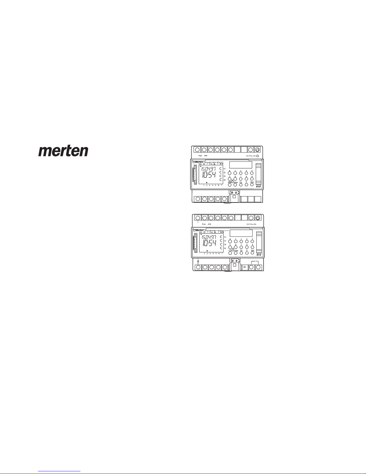
Year time switch REG-K/4/324 Year time switch REG-K/4/324 DCF77

4
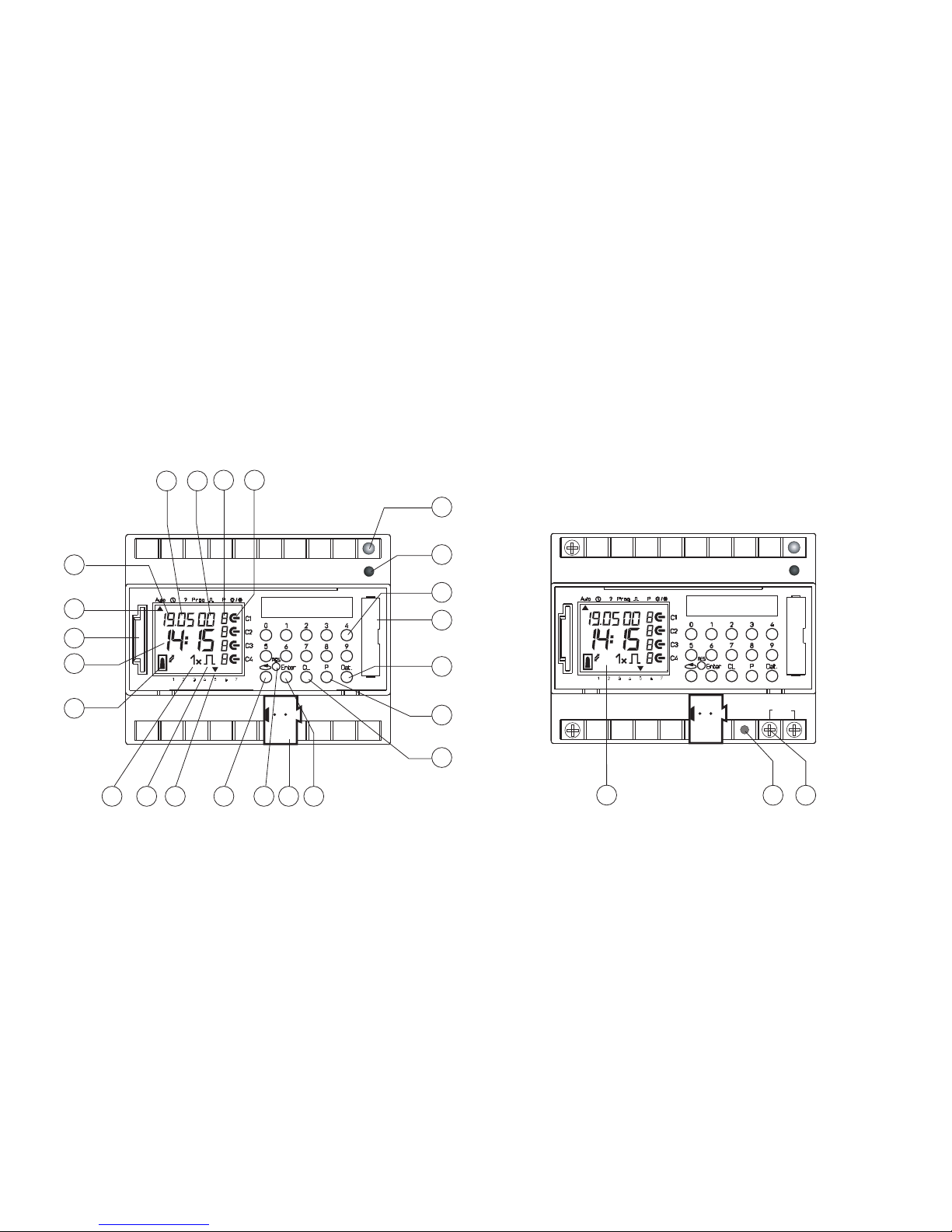
1.0 Description 2.0 Features
1Display data exchange with memory card
2Display hours
3Interface
4Cursor for program selection
5Display date day
6Display date month
7Display year
8Random indicator /P 1 .. 9 / Manual ON (H o/ Manual OFF (H p)
9Display status ON = oOFF = p
10 LED-BCU
11 BCU-Prog.button
12 Buttons 0 – 9 for program entry
13 Battery compartment
14 Button for entry of date switchings
15 Button for entry of priority programs/changes
16 Button for cancellation of programs and program steps
17 Button for entry of input
18 Bus-connection
19 RES = Reset / the micro-processor makes a defined new start
20 Program selection button for menu selection
21 Cursor for display of days of the week 1 = Monday,2 = Tuesday ...
22 Display for pulse programming
23 Display 1 x shows single switchings
24 Bus connection terminal DCF
25 LED lights up with DCF antenna reverse polarity
26 Display DCF77 reception
– 4-Channel Yearly Time Switch
– Time switch programming or PC programming using Windows 95 / 98 / 2000 /
WIN NT with software
– The time switch can be programmed up to the year 2063 in advance
– Data transfer and security possible with memory card
– Data can be transferred from time switch to time switch, from time switch to
PC and vice versa
– Functions: switching, dimming, transmitting time, receiving time
– BCU integrated in unit
– 324 switchings for free block formation of channels and week days
– Stipulating public holidays without a fixed date
– Permanent switching times by means of EEPROM
– Day/Week/Year program
– Random program
– Pulse program
– Switching times: ON or OFF delay
– automatic stipulating of public holidays without fixed date
– 1x-function for all date-related switching times
– 10 priority programs consisting of 10 individual weekly programs per channel
– Time limited permanent switching ON/OFF
– Approx. 1.5 years battery reserve by means of exchangeable environmentally
friendly lithium cell
– Option: radio controlled
– Up to 10 time switches or even products can be connected to one radio anten-
na.
In spite of expensive protection measures, exceptionally strong magnetic
fields can lead to the destruction of the micro-processor controlled time
switch.
We therefore recommend attention be given to the following
points before installation:
Use separate lead for the mains voltage supply.
Suppress inductive loads with suitable RC filters.
Do not mount product in direct proximity to sources of interference as
e. g. transformers, contactors, PCs and TV and communication
equipment.
After suffering intereference, we recommend, before re-setting, a RESET
with a new initial set up (chapter 5.3).
Strongly heat-generating products on the right side of the product shor-
ten the life of the battery.
DANGER
Risk of fatal injury from electrical current.
All work carried out on the unit may only be performed by skilled
electricians. Observe the regulations valid in the country of use, as
well as the valid KNX guidelines.
The time switch:
-> Must only be operated with the data from the product database
-> Must only be used in dry areas
-> The time switch is suitable for use in environmental conditions with
normal pollution
-> The time switch is suitable for mounting on the 35 mm top-nat rail
Unauthorised modifications to the equipment render the warranty invalid.
5
3.0 Application
3.1 Safety Instruction
3.2 Installation Instructions
3.3 Electrical Connection
Busline
The time switch controls connected bus participants via a group address.
It transmits either 1, 2 or 8-bit telegrams, including the time.
With the time program and the corresponding application, the time can be
transmitted and received via the BUS.
Transmission of current switch-time or date telegrams is only possible in auto-
matic mode.

6
3.4 Technical Data
3.5 Illustration of Dimensions
Description: Yearly-Time-Switch
Program type: Day/Week
Operating voltage: Bus-connection
Interval consumption: < 150 mW incl. BCU
Memory locations: 324
Minimum switching time: 1 second/minute
Minimum pulse: 1 second
Switching accuracy: Accurate to the second
Accuracy: ±1 sec./day at 20 °C
Power reserve: Lithium Cell 1.5 years at 20 °C
Permissible ambient temperature: –10 °C ... +50 °C (–10T50)
Protection class: II if installed according to EN 60335
Enclosure type: IP 20 in accordance with EN 60529
Type: 1 BSTU in accordance with EN 60730-1, -2, - 7
Operating voltage for supply
of the antenna: 230 V - 240 V AC -10 % +6 %
Antenna for the reception of the radio signal is required
Time base: Radio exact
(with power reserve quartz operated)
Max. distant of the radio antenna: 200 m
Enclosure type: IP 54 in accordance with EN 60529
Max. loading: 10 products
Note deviating technical data on the rating plate
Rights to technical improvements are reserved.
Note
The time switches conform to the European Regulations 73/23/EEC (low voltage
rules) and 89/336/EEC (EMV-Regulations).
If the time switches are used with other products in one installation, attention
must be given to ensure that the whole installation does not cause radio interfe-
rence.

In the event of a power failure, the battery back-up provides for the main-
tenace of correct time (approx. 1.5 years). Even without power and with a
drained battery, the switching times remain permanently stored.
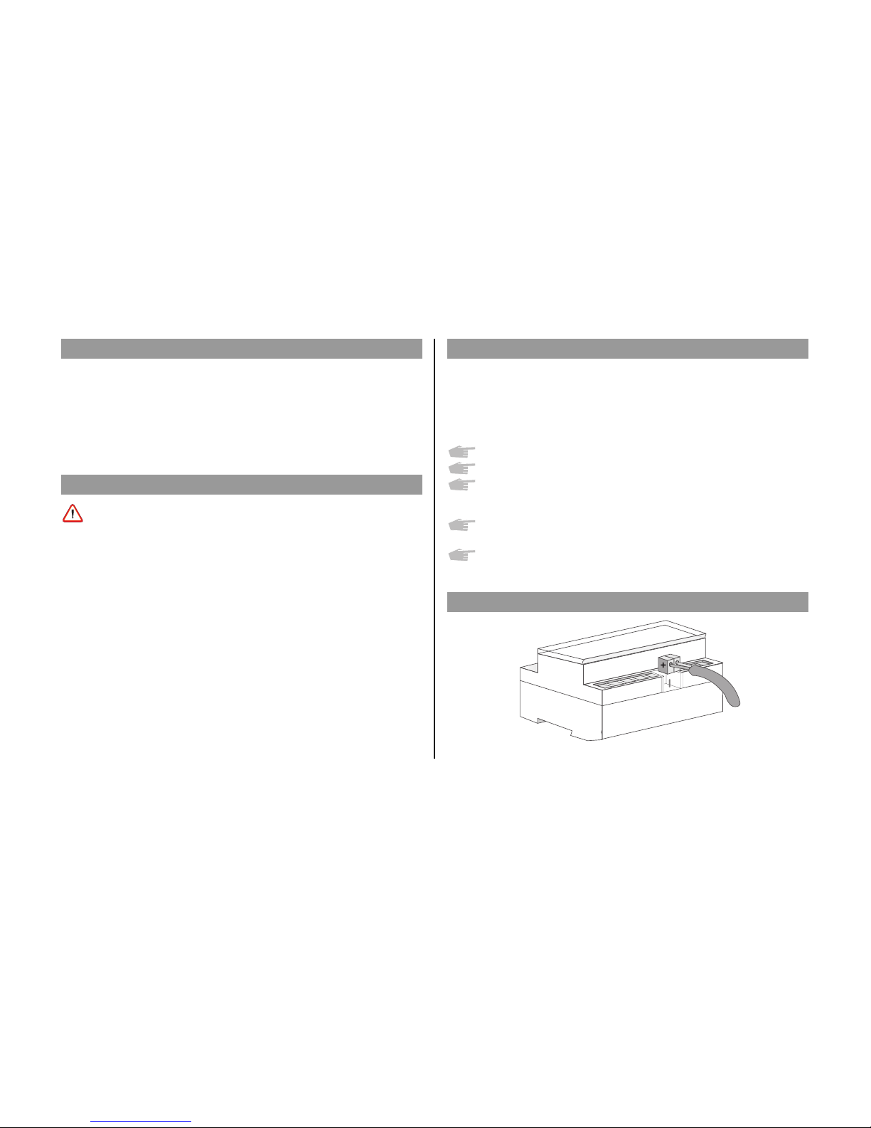
– Note the polarity of the lithium battery.
– Insert the lithium battery into the holder (see diagram 1).
– Push the battery holder into the battery compartment.
– Press the battery holder down, untl it audibly locates.
7
Important Instructions
Battery changing with mains voltage
All memorised program data is maintained
Battery changing without mains voltage
Note: date and time are lost.
1. Lift the battery draw with a suitable screw driver (see diagram 3).
2. Remove the lithium battery from the holder (see diagram 2).
3. Note the polarity of the new lithium cell.
4. Insert the Lithium battery into the holder (see diagram 1).
5. Push the battery holder into the battery compartment.
6. Press the battery holder down until it audibly locates.
7. Dispose of lithium battery in an environmentally friendly way .
Dia. 1
Dia. 2
4.0 Power Reserve
4.1 Battery Loading
4.2 Battery Changing
8
5.0 Initial Operation
5.1 Entry Adjustment
Ensure that the lithium battery is located (Chapter 4.1)
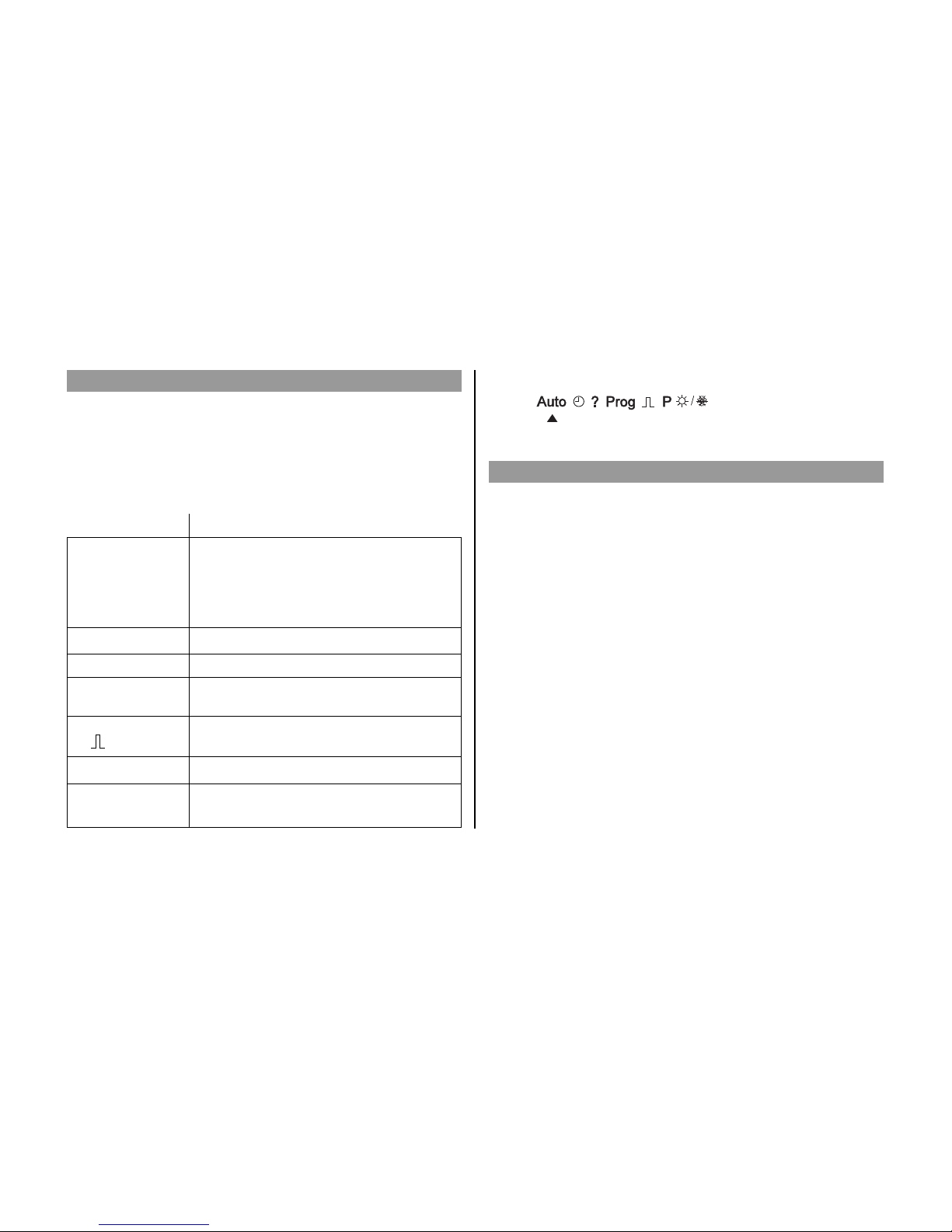
Press the vbutton to move the cursor ▲.
The cursor moves eacht time a menu item button is pressed.
Auto (Automatic Program)
– Programmed switching times determine the
switching programm
– Switching override (Manual ON/OFF)
– Random ON/OFF
n– Set / change date and time
?– Interrogate, change, cancel, completely cancel
Prog – Programming of date, weekly and 1x switching
times
– Programming of date, weekly pulses, 1x pulse,
ON and OFF switching delays
Pe.g. public holiday, vacation, or holiday program
s/f– Programming and change of Summer/Winter time
switching
Cursor below symbol:
Ending Programming: use v button, and place cursor ▲ into following
position .
The time switches contains a prompt facility. Follow the flashing
symbols. They show the programming sequence.
Entry Adjustment:
What to do when a wrong value has been entered in error?
Cancel the program step again:
– press button CL = one step back
– press button CL repeatedly = repeated steps back
When wrong value flashes:
– enter correct value with buttons 0 ... 9
or when programming channels or week-days:
or in the event of a wrong entry:
– press the same button again
Note:
Only the last entry will be cancelled.

On initial operation press button RES with a pointed object e.g. pencil, and after-
wards release it.
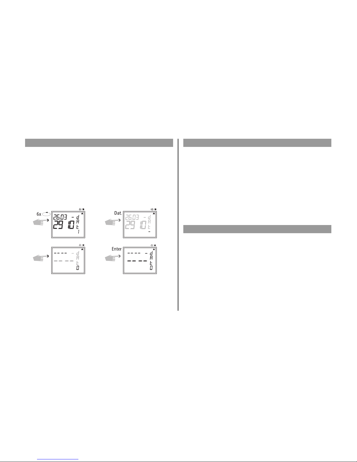
Example:
The time switch is to be set up on 19.05.2000 at 9.25
5.2 Setting date and time
5.3 Selection Schedule for Automatic Summer-/Winter time
9
date day
year
minute
store
hour
date month
Note:
After the initial operation (Chapter 5.3) automatic Summer/Winter time is
already programmed.
Basic setting is for Central Europe: dat 1.
If another or no change over standard is required, this can be changed at
any time, as described in Chapters 5.4 – 5.5.
Setting Commen- Commen- Area
cement cement
dat 0 no change no change
dat 1 last Sunday last Sunday EU
in March in October
2:00 ➔ 3:00 3:00 ➔ 2:00
dat 2 last Sunday last Sunday
in March in October UK
1:00 ➔ 2:00 2:00 ➔ 3:00
dat 3 1st Sunday last Sunday North
in April in October America
2:00 ➔ 3:00 3:00 ➔ 2:00
dat 4 individual Summer/Winter time table,
programmable only with software
Back into automatic program with button v.
Default REG/K4/324 dat 1
Select the new switching time (Chapter 5.3).
Example: basic setting dat 1
Change to: new regulation dat 0
Note: For radio controlled time switch (REG-K/4/324 DCF77) dat 0 is
necessary.
New dat 0 Store
AdjustSelect
5.4 Changing Automatic Summer/Winter time
5.6 Connection and Adjustment of the Radio Antenna
5.5 Radio Time Switch
10
The operation of the radio time switch is exactly the same without DCF-antenna.
The correct time, date and Summer-/Wintertime change-over set themselves
automatically with me DCF77 radio receiver.
Interesting Details:
– Accuracy of the radio receiver +/– 1 sec. in 1,000,000 years
– Transmitter location is Mainflingen near Frankfurt
– Transmitting radius of the transmitter approx. 1000 km
– Synchronisation is effected after initial setting-up and then daily at
night.
We recommend the following mounting positions:
– outside the control box (at least 4 m away)
– under the roof
– or in a protected position out of doors
Avoid mounting positions near:
– radio transmitting installations
– radiological equipment
– television and personal computers
0

D. Connecting several radio time switches to the
DCF antenna
1. First, connect only one time switch to the 230 V mains supply, then connect
to the bus line.
Observe the following when connecting the antenna:
2. Only after this, connect further time switch devices to the antenna.
The connection to the DCF antenna may take the form of a star, bus or tree
topology, see Fig. 1).
Note: If an LED at the DCF lights up, simply reverse the polarity at this
connection!
3. Following this, connect the other devices first to the 230 V mains supply
and then to the bus line.
4. Align the antenna, see Chapter C.
11
A. Operation without DCF77 radio reception
1. Connect the bus line only.
2. In this case, set the summer/winter change to the correct changeover
standard, see Chapter 5.3/5.4.
B. FW/S connection with radio reception
1. First connect the radio time switch to the 230 V mains supply and then to the
bus line.
2. Connect only antenna to the time switch. In this case, the polarity of the
connection is very important. The antenna signal is safety extra-low volta-
ge. Ensure that there is safe isolation from the voltage supply.
C. Adjusting the DCF radio antenna
1. Set the radio antenna so that the LED
installed in the front flashes at
one second intervals.
DCF 77
Busanschluß
DCF 77- Busanschluß
LED
+
-
+
L
N
N
L
Frankfurt a.M.
N
L
DCF 77DCF 77
LEDLED
Busanschluß
+
-
++
L
N
L
N
fig. 2
fig. 1
KNX busline
KNX busline
Year time switch REG-K/4/324 DCF77
DCF77 busline
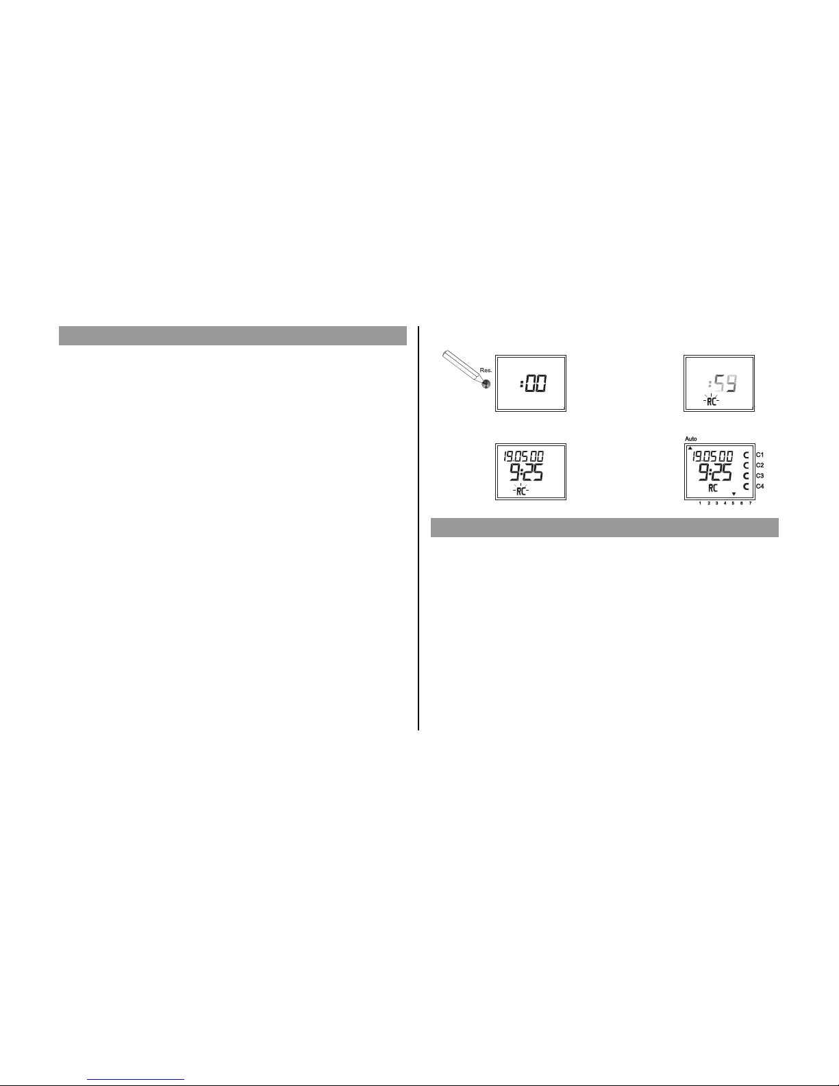
A. Setting-Up Automatically
Note: During synchronisation press no buttons!
The synchronisation test would be discontinued immediately.
To obtain a new start after this, RES button must be pressed again.
1. The display counts from 00 to 59 (see illustration 2)
Depending on the reception quality of the DCF77 signal, this
procedure can be repeated several times.
2. If the time swtich has received the whole of signal, RC goes on
flashing.
Only after a further signal is received, does the RC symbol stop.
The status of the channels are displayed (see illustration 3).
The clock is now ready.
B. Setting-Up Manually
Tip: If the clock, on the initial set-up, does not synchronise even after
several attempts, possibly because of a disturbed reception signal,
we recommend setting-up as described in Chapter 5.3.
The clock will then try once more to synchronise itself on the signal,
during the night.
5.7 Initial Operation of the Radio Time Switch
12
5.8 Forced Transmitter Call
The synchronisation of the time switch is effected after the initial setting-up, then
daily between 1.58 and 3.13.
A radio synchronisation can be called up manually during the day
(transmitter call).
Start of the Transmitter Call
1. Press Dat Button for approx. 3 secs.
2. Then release.
The timeswitch synchronises itself on the DCF77 signal.
In the LCD display can be seen:
The RC symbol flashes only during a DCF77 synchronisation!
If the time switch has synchronised itself, a program review takes place.The chan-
nels take on, afterwards, the specified switching positions, from the individual
program.
The RC symbol is permanently in the LCD display.
Example: The time switch has synchronised itself on 19.5.2000 at 9.25.
2)
3)

With the cursor in Pos. n, any flashing value, the actual time or date, can be
changed with the buttons 0 .. 9.
5.9 Changing Date / Time
13
111
11
11
1
222
22
22
2
333
33
33
3
444
44
44
4
555
55
55
5
666
66
66
6
777
77
77
7
777
77
77
7
AutoAuto
??
Dat. 0, 9
2
7
1X
2,0
Enter
Enter
Enter
1 2 3 4 5 6 7
C1C1
C1
C2C2
C2
C3C3
C3
C4C4
C4
Change date e.g. from
19.5.2000 to 20.5.2000
Change time only e.g.
from 9.25 to 9.27
Each channel can be manually switched in automatic menu to permanently ON.
A permanent switching has highest priority. The channel remains in the perma-
nently ON switching position until manually cancelled.
Example: Channel 1permanent ON.
Example: Channel 1permanent OFF.
6.0 Manual Intervention in the Program
6.1 Permanent ON / OFF
11
1
22
2
33
3
44
4
55
5
66
6
77
7
77
7
C1 C1
C1
C2 C2
C2
C3 C3
C3
C4 C4
C4
Auto Auto Auto
11
P
Kanal 1 EIN
Permanent
11
1
22
2
33
3
44
4
55
5
66
6
77
7
77
7
C1 C1
C1
C2 C2
C2
C3 C3
C3
C4 C4
C4
10
P
Kanal 1 AUS
Permanent
Auto
Auto
Auto
Each channel can be manually switched in automatic menu to permanently OFF.
A permanent switching has highest priority. The channel remains in the perma-
nently OFF switching position until manually cancelled.
After cancellation of a permanent switching the time switch effects a program
recall. This results in the time switch checking the stored program and imple-
menting the correct switching condition.
– Press Enter repeatedly, until the cursor is below Auto
– or follow the line and change the actual time.
Select Dat
Date Day
Store month
Store year Store
Adjust
Adjust
Hour Channel 1
Channel 1
ON
OFF
Each channel can be switched OFF manually in the automatic program. An over-
ride switching in the automatic program is corrected again by the next switching
command. (The H symbol is turned off).
Select Channel: e.g. Button 1 = Channel C1, Button 2 = Channel C2 etc.
Select Status: Button 1 = Switch ON, Button 0= Switch OFF
Example: Switch OFF Channel C2 manually, Button 2, press.
6.2 Manual ON / OFF (override switching)
14
Each channel can be switched ON manually in the automatic program. In which
case, the symbol H = hand appears in the display.
An override switching is cancelled again by the next switching command. The H
display is turned off.
Select Channel: e.g. Button 1 = Channel C1, Button 2 = Channel C2 etc.
Select Status: Button 1 = Switch ON, Button 0= Switch OFF
Example: Switch ON Channel C2 manually, press button 2, once (press 1).
1 11 12 22 23 33 34 44 45 55 56 66 67 77 7
C1 C1C1 C1
C2 C2C2 C2
C3 C3C3 C3
C4 C4C4 C4
Auto Auto
21
1 11 12 22 23 33 34 44 45 55 56 66 67 77 7
C1 C1C1 C1
C2 C2C2 C2
C3 C3C3 C3
C4 C4C4 C4
Auto Auto
20
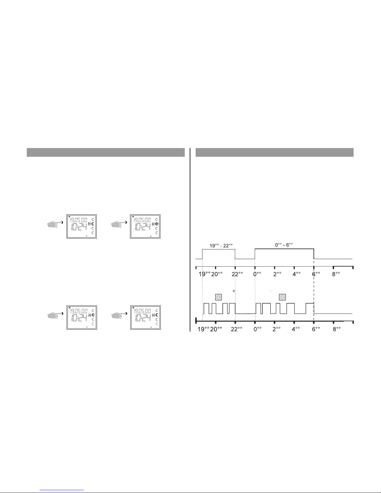
General Comment
A random program causes the time switch to switch ON or OFF at random bet-
ween one or more pairs of switchings (ON and OFF switching time).
Duration of the random ON and OFF switching time approx.
10 – 120 minutes.
The random program can be selected individually for each time channel.
Example:
Between 19.00 and 22.00 random ON (display:r)
Between 0.00 and 06.00 random ON (display:r)
6.3 Random Program
Programmed switching pairs
Random
Program
Random
Program
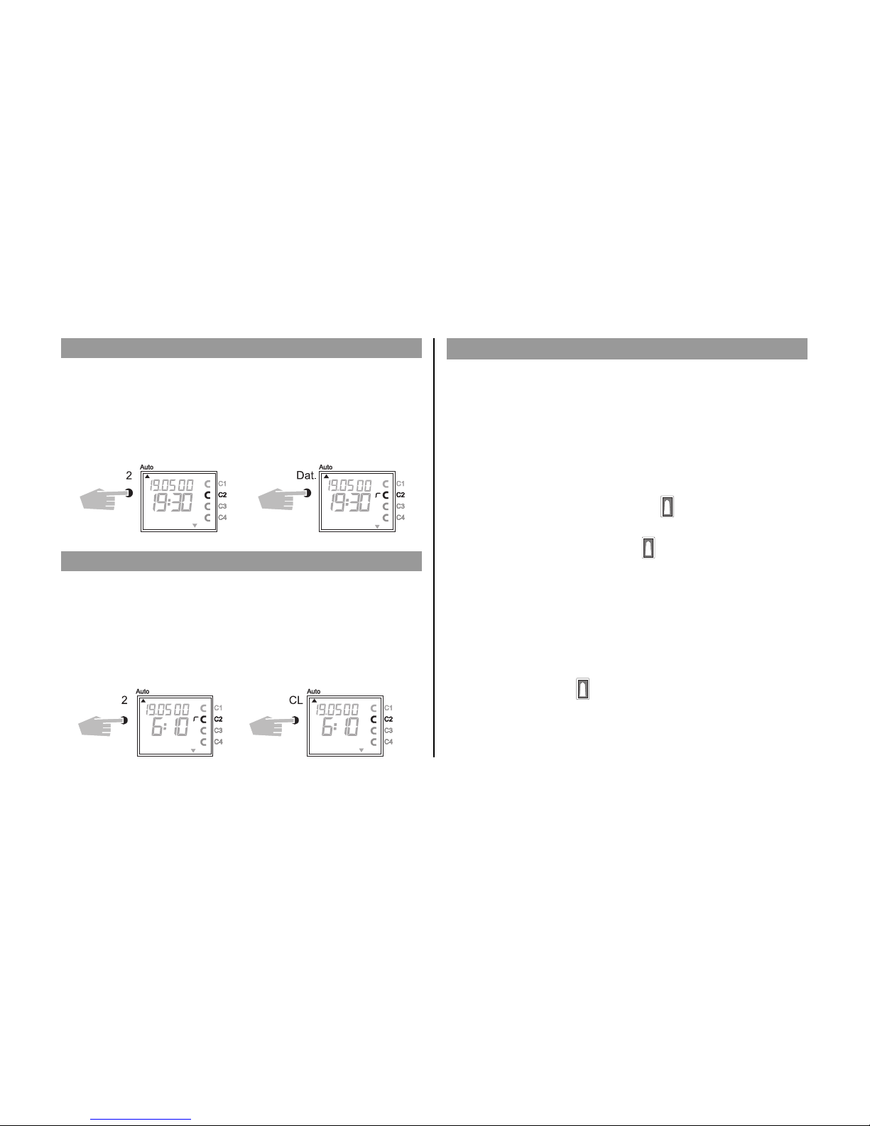
A random program override switching can be interrupted at any time.
After cancellation of the random program override switching, the time switch car-
ries out a program review. This causes the time switch to inspect the stored pro-
gram and then take up the correct switching status.
Example: Stop random program Channel C2.
Note: The symbol r turns OFF.
6.4 Random Program Start
6.5 Stop Random Program / Override Switching
15
A random program can be switched ON manually in the automatic program
(Auto) at any time. It remains active until switched OFF (chapter 6.5).
Note: If the random program is active in a channel, the symbol r (random)
appears beside the channel.
Example: Switch ON random program in Channel C2.
6.6 Locking/ Unlocking the Keyboard
Effect:
The memory card allows you to prevent operation of the device by unauthorized
persons.
In this case time switch query and programming are impossible without the
memory card.
Locking the keyboard
1. Insert the memory card into the data interface.
2. Press key 8for approx. 3 secs until the icon is flashing.
Operating the time switch
If after a button is pressed and the Symbol is blinking, the keyboard is locked.
1. Insert the memory card into the data interface.
2. You can the select the desired program using the v key.
3. Now you can remove the memory card in order to continue programming.
When the time switch returns to auto mode, the keyboard is locked.
Canceling the keyboard lock
1. Insert the memory card into the data interface.
2. Press key 8 until the icon appears.
3. Press key 8 for approx. 3 secs until the icon disappears.
4. Remove the memory card.
Now the time switch can be operated again without obstruction.
16
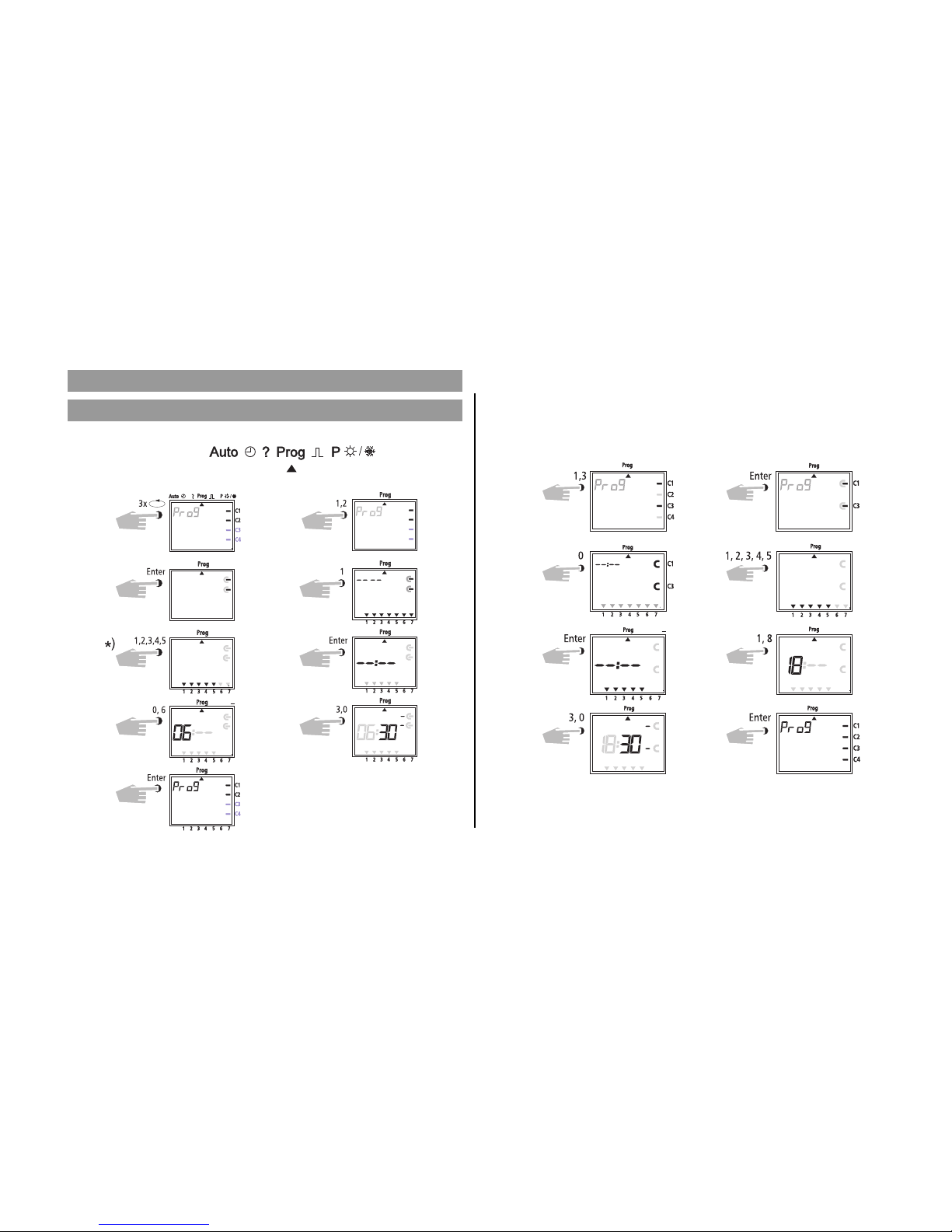
e.g.: Channels C1 and C3 are to switch on at 6.30 from Mon to Fri o
Place cursor ▲ in pos.
7.0 Programming
7.1 Weekly Program, set switch ON time
Select Prog
Switch ON
Channel 1 + 3
Confirm days
Minutes
*) Press button 0
Switching time activated daily
Confirm Channel
Weekdays
Hours
Storage Program
Example 2: Weekly program – set switch OFF time
– Channels C1 and C3 are to switch OFF at 18.30 from Mon to Fri p
Additional programming as described, or back into the automatic program with
button v.
Channel 1 + 3 Confirm Channel
Week Days
Hours
Store
Switch OFF
Confirm days
Minutes

Example.: Channel C1 is to switch ON yearly on the 1.5 at 7.30
Place cursor ▲ in pos.
17
7.2 Programming Date Program
Select Prog. Channel 1
ON
Date Day
Hours
Store
Confirm Channel
Date
Date Month
Minutes
Additional programming as described or back into the automatic program with
button v.
1 2 3 4 5 6 7
C1C1
C2C2
C3C3
C4
C4
C4
C3 C3
C2 C2
C1 C1
C2 C2
C4C4
C4
Prog
Prog
Prog
Prog Prog
Prog Prog
Prog Prog
Prog Prog
Enter
Enter
1
2
Dat 1, 0
0, 5 0, 8
3, 0 1
3x
Example: Channel C2, 1 switch ON on the 10.5 at 8.30
Note: Only date related switching times can be programmed with the
function 1x see illustration 10. Once the switching time is effected,
it cancels itself automatically at mid-night.
Additional programming as described or
back into the automatic program with
button v
7.3 Programming Single Switching Time
10)
Select Prog Channel 2
Confirm Channel ON
Date Date Day
Date Month Hours
Minutes 1 x
Store
18
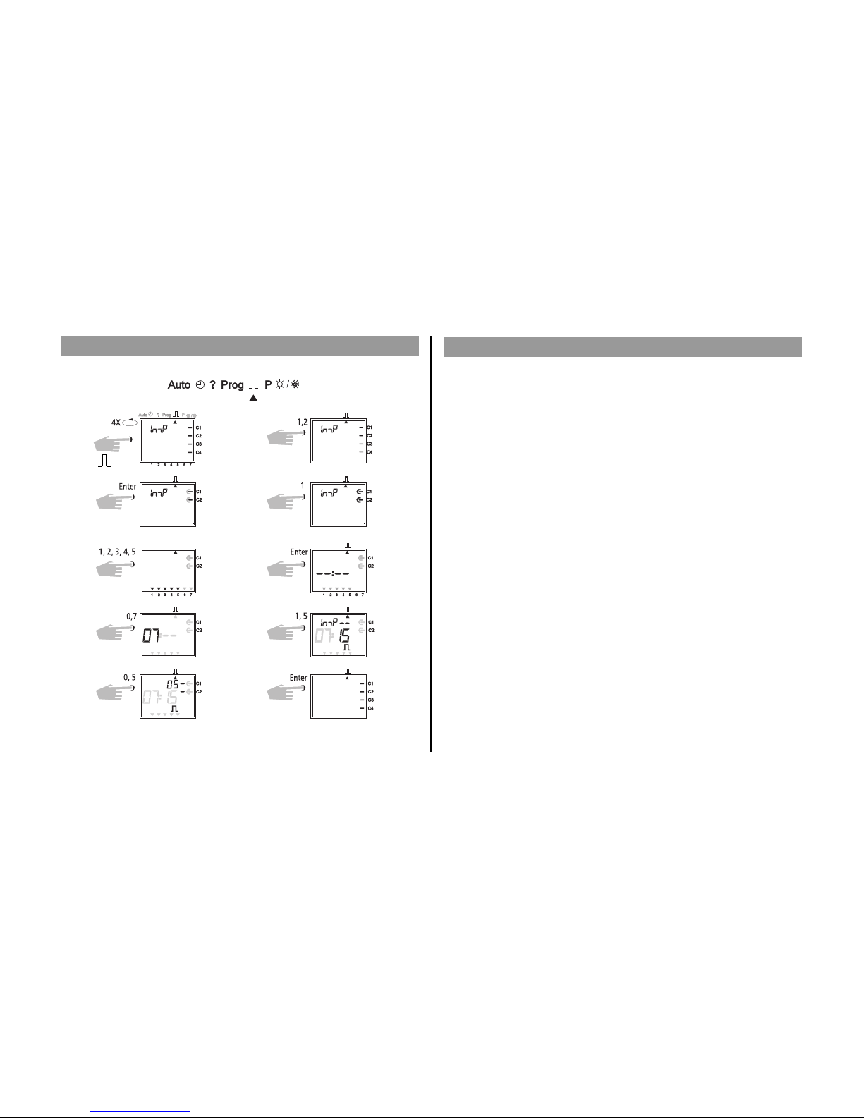
7.4 Programming Pulse Program
Example: Channels C1 and C2 pulse duration: 5 secs from Mon to Fri at 7.15.
Place cursor ▲ in pos.
Select
Switch ON
Channel 1 + 2
Confirm Days
Minutes
Store
Confirm
Week Days
Hours
Pulse 5 sec.
Note After a time adjustment, pulses are only effected, which are programmed at
least one minute after the time adjustment.
8.0 Priority Program
With the time switches up to 9 different weekly programs can be
performed in addition to the normal weekly program. A firm weekly program
P1 ... P9 can be requested at any fixed periods of time.
That is, the programming consists of:
1. Setting the weekly program (see Chapter 8.1)
2. Setting commencement and completion date (see Chapter 8.2)
If the time period of several weekly programs cut across one another, the pro-
gram with the highest index number prevails e.g. weekly program P9 prevails
over weekly program P3.
In order to maintain control, we recommend that the various weekly programs
are noted in the table at the end of the user instructions.
Switching times are executed in the following order:
– Permanent switching
– Time limited permanent switching. Chapter 8.3 (out priority over ON).
– Date switching times. Chapter 7.3 (out priority over ON).
– 1x switching times. Chapter 7.3.
– Weekly program with priority. Chapter 8.2/8.3 (P9 priority over P1).
– Weekly program. Chapter 7.1/7.2.
– etc.

19
Weekly Program Schedule with Priority
Highest Priority
weekly program P9
weekly program P8
weekly program P7
weekly program P6
weekly program P5
weekly program P3
weekly program P2
weekly program P1
weekly program P4
Channel C3 + C4 switch ON
Monday-Friday 6.30
pulse duration 5 secs.
Channel C3 + C4 switch ON
Monday-Friday at 7.15
pulse duration 5 secs.
Channel C1 + C2 at ON o
16.15 daily.
Channel C1 + C2 at OFF 20.00 p
Start
e.g. 8.4
Finish
e.g. 27.5
Start
e.g. 21.7
Finish
e.g. 7.9
Standard
Weekly Program
Weekly Program
P3 Standard
Weekly Program
Weekly Program
P4 Standard
Weekly Program
When changing to a new weekly program (e.g. on 8.4 at 0.00 hr), all channels in
questions are switched as if the new weekly program has been valid for some
time. This means the new weekly programme makes a review of the program.
8.1
8.2
EIN
AUS
Relais
P1
P2
P3
P4
P5
P6
P7
P8
P9
Standard
+
weekly program
„Standard“
weekly program
„Priority
1“
weekly program
„Priority
2“
weekly program
„Priority
3“
weekly program
„Priority
4“
weekly program
„Priority
5“
weekly program
„Priority
6“
weekly program
„Priority
7“
weekly program
„Priority
8“
weekly program
„Priority
9“
Priority times
P1-P9
Date
switching
times
Permanently
ON/OFF
ON
OFF
RELAY

20
8.1 Programming Weekly Program with Priority P1 .. P9
The time period of a weekly program P1 .. P9 is fixed by entering a commence-
ment and finishing date. The weekly program begins at 0.00 on the commence-
ment date and ends at 2400 on the finishing date.
Example: As opposed to the normally active program on Channel C2 from
8 April until 27 May, the individual priority program with index P1 is to beco-
me effective. In the fixed time period with priority sequence P1 .. P9, the whole
standard program (without priority sequence) is suppressed.
8.2 Setting Time Period for Weekly Program P1 .. P9
Additional programming as described or with button v back into the auto-
matic program.
Example Channel C1 and C2 switch on daily at 8.15
Weekprogram get priority sequence P1.
Note: Pulse switching times can also be
fixed with priority sequence. For
weekly programs with priority, any
number of ON/OFF switching com-
mands can be specified.
Select Prog Select Channel
Confirm Switch ON
Daily Hours
Minutes Priority P1
Store
Select P Channel 2
Date Start
Confirm
Date End
Prio select Store
A. Recurring annually
Confirm
This manual suits for next models
1
Table of contents
Other merten Switch manuals


Popular Switch manuals by other brands


Analog way
Analog way Pulse quick start guide

Hewlett Packard Enterprise
Hewlett Packard Enterprise Aruba 3810 Management and configuration guide

Pilz
Pilz PSEN ma1.4n-50 operating instructions

Juniper
Juniper QFX5220 Hardware guide

Kindermann
Kindermann Multimatrix 8 operating instructions

Tektronix
Tektronix Keithley 3700A Series user manual