MESSER SolidWELD TIG 185AC/DC FP User manual

TIG 185AC/DC FP
Operating manual


03TIG 185AC/DC FP Operating manual
Important Notice
This document has been prepared by Messer Canada Inc. ABN 95 000 029 729, as general information and does not contain and is not to be taken as containing any specific recommendation. The document has
been prepared in good faith and is professional opinion only. Information in this document has been derived from third parties, and though Messer believes it to be reliable as at the time of printing, Messer makes no
representation or warranty as to the accuracy, reliability or completeness of information in this document and does not assume any responsibility for updating any information or correcting any error or omission which may
become apparent after the document has been issued. Neither Messer nor any of its agents has independently verified the accuracy of the information contained in this document. The information in this document is
commercial in confidence and is not to be reproduced. The recipient acknowledges and agrees that it must make its own independent investigation and should consider seeking appropriate professional recommendation
in reviewing and evaluating the information. This document does not take into account the particular circumstances of the recipient and the recipient should not rely on this document in making any decisions, including
but not limited to business, safety or other operations decisions. Except insofar as liability under any statute cannot be excluded, Messer and its affiliates, directors, employees, contractors and consultants do not accept
any liability (whether arising in contract, tort or otherwise) for any error or omission in this document or for any resulting loss or damage (whether direct, indirect, consequential or otherwise) suffered by the recipient of
this document or any other person relying on the information contained herein. The recipient agrees that it shall not seek to sue or hold Messer or their respective agents liable in any such respect for the provision of this
document or any other information.
This operating manual provides the basic knowledge required
for TIG Welding, as well as highlighting important areas of how
to operate the TIG 185AC/DC FP.
With normal use and by following these recommended steps,
your TIG 185AC/DC FP machine can provide you with years of
trouble-free service. Messer equipment and technical support is
available through the national Messer Customer Service Centre
or contact your local Messer outlet.

04 TIG 185AC/DC FP Operating manual
Contents.
Page
03 Welcome to a better way of welding
06 1. Recommended safety precautions
1.1 Health hazard information
1.2 Personal protection
1.3 Cylinder safety
1.4 Electrical shock
1.5 User responsibility
08 2. Gas Tungsten Arc Welding (GTAW/TIG)
2.1 Introduction
2.2 Process
2.3 Process variables
2.4 Shielding gas selection
2.5 Consumable selection
2.6 Non-consumable tungstens –
tungsten electrode selector chart
12 3. Shielded Metal Arc Welding (SMAW)
3.1 Introduction
3.2 Process
3.3 Welding machine
3.4 Welding technique
3.5 Electrode selection
3.6 Types of joints
15 4. Package contents
16 5. TIG 185 AC/DC installation
5.1 Installation for TIG setup
5.2 Installation fro TIG setup with optional foot control
5.3 Installation for MMA process

05TIG 185AC/DC FP Operating manual
Page
17 6. Control panel
6.1 Function switches
6.2 Adjustment knobs
6.3 Indicator function
18 7. TIG 185 AC/DC operation
7.1 Operation for AC welding
7.2 Operation for DC welding
7.3 Operation for foot control (TIG welding only)
7.4 Operation for MMA welding
19 8. Technical specifications
20 9. Troubleshooting guide
22 10. Periodic maintenance
10.1 Daily maintenance
10.2 Regular power source maintenance
23 11. Warranty information
11.1 Terms of warranty
11.2 Limitations on warranty
11.3 Warranty period
11.4 Warranty repairs
24 12. Recommended safety guidelines
25 13. Operating manual Appendix

06 TIG 185AC/DC FP Operating manual
1. Recommended safety precautions.
Clothing
Suitable clothing must be worn to prevent excessive exposure to
UV radiation and sparks. An adjustable helmet, flameproof loose
fitting cotton clothing buttoned to the neck, protective leather
gloves, spats, apron and steel capped safety boots are highly
recommended.
Recommended filter shades for arc welding
Less than 150 amps
Shade 10*
150 to 250 amps Shade 11*
250 tp 300 amps Shade 12
300 to 350 amps Shade 13
Over 350 amps Shade 14
* Use one shade darker for aluminium
1.3 Cylinder safety
1Cylinder valve hand-wheel, 2Back-plug, 3Bursting disc
Operator wearing perso-
nal protective equipment
(PPE) in safe position
Backview of typical
cylinder valve
1
2
3
Ten points about cylinder safety
1. Read labels and Material Safety Data Sheet (MSDS) before use.
2. Store upright and use in well ventilated, secure areas away
from pedestrian or vehicle thoroughfare.
3. Guard cylinders against being knocked violently or being
allowed to fall.
4. Wear safety shoes, glasses and gloves when handling and
connecting cylinders.
5. Always move cylinders securely with an appropriate trolley.
Take care not to turn the valve on when moving a cylinder.
6. Keep in a cool, well-ventilated area, away from heat sources,
sources of ignition and combustible materials, especially
flammable gases.
7. Keep full and empty cylinders separate.
1.1 Health hazard information
The actual process of welding is one that can cause a variety
of hazards. All appropriate safety equipment should be worn at
all times, i.e. headwear, respiratory, hand and body protection.
Electrical equipment should be used in accordance with the
manufacturer’s recommendations.
Eyes
The process produces ultraviolet rays that can injure and cause
permanent damage. Fumes can cause irritation.
Skin
Arc rays are dangerous to uncovered skin.
Inhalation
Welding fumes and gases are dangerous to the health of the
operator and to those in close proximity. The aggravation of pre-
existing respiratory or allergic conditions may occur in some
workers. Excessive exposure may cause conditions such as nausea,
dizziness, dryness and irritation of eyes, nose and throat.
1.2 Personal protection
Respiratory
Confined space welding should be carried out with the aid of a fume
respirator or air supplied respirator.
• You must always have enough ventilation in confined spaces. Be
alert to this at all times.
• Keep your head out of the fumes rising from the arc.
• Fumes from the welding of some metals could have an adverse
effect on your health. Don’t breathe them in. If you are welding
on material such as stainless steel, nickel, nickel alloys or
galvanised steel, further precautions are necessary.
• Wear a respirator when natural or forced ventilation is not good
enough.
Eye protection
A welding helmet with the appropriate welding filter lens for the
operation must be worn at all times in the work environment. The
welding arc and the reflecting arc flash gives out ultraviolet and
infrared rays. Protective welding screen and goggles should be
provided for others working in the same area.

07TIG 185AC/DC FP Operating manual
8. Keep ammonia-based leak detection solutions, oil and grease
away from cylinders and valves.
9. Never use force when opening or closing valves.
10. Don’t repaint or disguise markings and damage. If damaged,
return cylinders to Messer immediately.
Cylinder valve safety
When working with cylinders or operating cylinder valves, ensure
that you wear appropriate protective clothing – gloves, boots and
safety glasses. When moving cylinders, ensure that the valve is not
accidentally opened in transit.
Before operating a cylinder valve:
• Ensure that the system you are connecting the cylinder into is
suitable for the gas and pressure involved.
• Ensure that any accessories (such as hoses attached to the
cylinder valve, or the system being connected to) are securely
connected. A hose, for example, can potentially flail around
dangerously if it is accidentally pressurised when not restrained
at both ends.
• Stand to the side of the cylinder so that neither you nor anyone
else is in line with the back of the cylinder valve. This is in case a
back-plug is loose or a bursting disc vents. The correct stance is
shown in the diagram.
When operating the cylinder valve:
• Open it by hand by turning the valve hand-wheel anti-clockwise.
Use only reasonable force.
• Ensure that no gas is leaking from the cylinder valve connection
or the system to which the cylinder is connected. Do not use
ammonia based leak detection fluid as this can damage the
valve. Approved leak detection fluid can be obtained from a
Messer centre.
• When finished with the cylinder, close the cylinder valve by hand
by turning the valve hand-wheel in a clockwise direction. Use
only reasonable force.
Remember NEVER tamper with the valve. If you suspect the
valve is damaged, DO NOT use it. Report the issue to Messer
and arrange for the cylinder to be returned to Messer.
1.4 Electrical shock
• Never touch ‘live’ electrical parts
• Always repair or replace worn or damaged parts
• Disconnect the power source before performing any
maintenance or service
• Ground all work materials
• Never work in moist or damp areas.
Avoid electric shock by:
• Wearing dry insulated boots
• Wearing dry leather gloves
• Never changing electrodes with bare hands or wet gloves
• Never cooling electrode holders in water
• Working on a dry insulated floor where possible
• Never hold the electrode and holder under your arm.
1.5 User responsibility
• Read the Operating Manual prior to installation of this machine.
• Unauthorised repairs to this equipment may endanger the
technician and operator and will void your warranty. Only
qualified personnel approved by Messer should perform repairs.
• Always disconnect mains power before investigating equipment
malfunctions.
• Parts that are broken, damaged, missing or worn should be
replaced immediately.
• Equipment should be cleaned periodically.
PLEASE NOTE that under no circumstances should any
equipment or parts be altered or changed in any way from the
standard specification without written permission given by
Messer. To do so, will void the Equipment Warranty.

08 TIG 185AC/DC FP Operating manual
2. Gas Tungsten Arc Welding (GTAW/TIG).
Shielding gas is directed into the arc area by the welding torch and
a gas lens within the torch distributes the shielding gas evenly over
the weld area. In the torch the welding current is transferred to
the tungsten electrode from the copper conductor. The arc is then
initiated by one of several methods between the tungsten and the
workpiece.
During TIG welding, the arc can be initiate by several means:
Scratch start
With this method, the tungsten electrode is physically scratched
on the surface of the workpiece and the arc is initiated at the
full amperage set by the operator. The incidence of the tungsten
melting at the high initiation amperage is high and tungsten
inclusions in the weld metal are quite common.
High frequency start
During High Frequency start, the arc will ‘jump’ towards the
workpiece if a critical distance is reached. With this method, there
is no incidence of tungsten inclusions happening. High Frequency is
only available on certain types of machines and it can affect nearby
electronic equipment.
Lift Arc™
During this method of arc initiation, the tungsten is actually touching
the workpiece. This occurs at very low amperage that is only
sufficient to pre-heat, not melt the tungsten. As the tungsten is
moved off the plate, the arc is established. With this method, there
is little chance of tungsten inclusion occurring.
2.3 Process variables
DCEN
When direct-current electrode-negative (straight polarity) is used:
• Electrons strike the part being welded at a high speed
• Intense heat on the base metal is produced
• The base metal melts very quickly
• Ions from the inert gas are directed towards the negative
electrode at a relatively slow rate
• Direct current with straight polarity does not require post-weld
cleaning to remove metal oxides.
2.1 Introduction
The Tungsten Inert Gas, or TIG process, uses the heat generated
by an electric arc struck between a non-consumable tungsten
electrode and the workpiece to fuse metal in the joint area and
produce a molten weld pool. The arc area is shrouded in an inert
or reducing gas shield to protect the weld pool and the non-
consumable electrode. The process may be operated autogenously,
that is, without filler, or filler may be added by feeding a consumable
wire or rod into the established weld pool.
2.2 Process
1Shielding gas, 2Arc, 3TIG filler rod, 4Weld pool, 5Collet,
6Tungsten Electrode, 7Workpiece
Schematic of the TIG welding process
1
2
3
4
5
6
7
Direct or alternating current power sources with constant current
output characteristics are normally employed to supply the welding
current. For DC operation the tungsten may be connected to either
output terminal, but is most often connected to the negative pole.
The output characteristics of the power source can have an effect
on the quality of the welds produced.

09TIG 185AC/DC FP Operating manual
Use of DCEN
For a given diameter of tungsten electrode, higher amperage can
be used with straight polarity. Straight polarity is used mainly for
welding:
• Carbon steels
• Stainless steels
• Copper alloys.
The increased amperage provides:
• Deeper penetration
• Increased welding speed
• A narrower, deeper, weld bead.
DCEP
The DCEP (reverse polarity) is different from the DCEN in the
following ways:
• High heat is produced on the electrode rather than on the base
metal
• The heat melts the tungsten electrode tip
• The base metal remains relatively cool compared to straight
polarity
• Relatively shallow penetration is obtained
• An electrode whose diameter is too large will reduce visibility
and increase arc instability.
Use of DCEP
• Intense heat means a larger diameter of electrode must be
used with DCEP
• Maximum welding amperage should be relatively low
(approximately six times lower than with DCEN).
Alternating current with high-frequency
Welding with alternating current combines both direct current
characteristics:
• In the positive phase, cleaning action occurs in the weld
puddle.
• During the negative phase, heat is concentrated in the weld
puddle.
• The above causes increased penetration.
1R]]OH
,RQV (OHFWURQV
1R]]OH
,RQV (OHFWURQV
1R]]OH
,RQV (OHFWURQV
1R]]OH
,RQV (OHFWURQV
1R]]OH
,RQV (OHFWURQV
1R]]OH
,RQV (OHFWURQV
DCEN – Narrow bead, deep penetration DCEP – Wide bead, shallow penetration
Average bead, average penetration

010 TIG 185AC/DC FP Operating manual
2.4 Shielding gas selection
Brass With argon, the arc is stable and there is little smoke.
Cobalt-based alloys Argon provides a stable, easy-to-control arc.
Copper nickel
(Monel)
Argon gives a stable, easy-to-control arc. Also used for welding copper nickel to steel.
Deoxidised copper Helium is preferred as it helps greatly in counteracting thermal conductivity of copper. A mixture of 75% helium
and 25% argon (Alushield Heavy) produces a stable arc, less heat than an arc produced with helium alone.
Nickel alloys (Inco-
nel)
Argon produces a very stable arc. Helium is recommended for automatic welding at high speeds
Mild steel For manual welding, argon is recommended. Successful welding depends on the skill of the welder. Helium is
preferred for:
• high speed automatic welding
• where deeper penetration than with argon is required
• small HAZ
Magnesium alloys Argon recommended with continuous high frequency AC. Produces good arc stability and good cleaning action.
0.5% Molybdenum Pure argon or helium is recommended. For good welding ductility, welding must be carried out in a draught-free
area.
Silicon bronze Argon decreases internal tension in base metal and in the weld since there is less penetration with this gas
compared to helium.
Stainless steel Argon is the most commonly used gas for stainless steel. Helium can be used if better penetration is required.
Titanium alloys Argon produces a stable arc. Helium is recommended for high speed welding.
2.5 Consumable selection
Filling rod
Filler rod diameter (mm) Thickness of metal (mm)
2 0.5–2
3 2–5
4 5–8
4 or 5 8–12
5 or 6 12 or more
2.6 Non-consumable tungstens – tungsten electrode selector chart
Aluminium alloys and magnesium alloys
Thickness range Desired results Welding
current
Electrode
type
Shielding gas Tungsten performance characteristics
All General
purpose
ACHF Pure (EW-P) Argon Balls easily. Low cost. Tends to spit at higher
currents. Used for non-critical welds only.
Zirconiated
(EW-Zr)
Argon Balls well. Takes higher current, with less
spitting and with better arc starts and arc
stability than pure tungsten.
2% Thoriated
(EW-Th2)
75% Argon/
25% Helium
Higher current range and stability. Better arc
starts, with lower tendency to spit. Medium
erosion.
Only thin sections Control penetration DCRP 2% Ceriated
(EW-Ce2)
Argon Helium Lowest erosion rate. Widest current range. AC
or DC. No spitting. Best arc starts and stability.
Only thick
sections
Increase
penetration or
travel speed
DCSP 2% Thoriated
(EW-Th2)
75% Argon/
25% Helium
Best stability at medium currents. Good arc
starts. Medium tendency to spit. Medium
erosion rate.
2% Ceriated
(EW-Ce2)
Helium Low erosion rate. Wide current range. AC or
DC. No spitting. Consistent arc starts. Good
stability.

011TIG 185AC/DC FP Operating manual
Copper alloys, Cu-NI alloys and nickel alloys
Thickness range Desired results Welding
current
Electrode
type
Shielding gas Tungsten performance characteristics
All General purpose DCSP 2% Thoriated
(EW-Th2)
75% Argon/
25% Helium
Best stability at medium currents. Good arc
starts. Medium tendency to spit. Medium
erosion rate.
2% Ceriated
(EW-Ce2)
75% Argon/
25% Helium
Low erosion rate. Wide current range. AC or
DC.
No spitting. Consistent arc starts. Good
stability.
Only thin sections Control penetration ACHF Zirconiated
(EW-Zr)
Argon Use on lower currents only. Spitting on starts.
Rapid erosion rates at higher currents.
Only thick
sections
Increase
penetration or
travel speed
DCSP 2% Ceriated
(EW-Ce2)
75% Argon/
25% Helium
Low erosion rate. Wide current range. AC or
DC.
No spitting. Consistent arc starts. Good
stability.
Mild steels, carbon steels, alloy steels, stainless steels and titanium alloys
Thickness range Desired results Welding
current
Electrode
type
Shielding gas Tungsten performance characteristics
All General
purpose
DCSP 2% Thoriated
(EW-Th2)
75% Argon/
25% Helium
Best stability at medium currents. Good arc
starts. Medium tendency to spit. Medium
erosion rate.
2% Ceriated
(EW-Ce2)
75% Argon/
25% Helium
Low erosion rate. Wide current range. AC or
DC.
No spitting. Consistent arc starts. Good
stability.
2%
Lanthanated
(EWG-La2)
75% Argon/
25% Helium
Lowest erosion rate. Widest current range on
DC.
No spitting. Best DC arc starts and stability.
Only thin sections Control penetration ACHF Zirconiated
(EW-Zr)
Argon Use on lower current only. Spitting on starts.
Rapid erosion rates at higher currents.
Only thick
sections
Increase
penetration or
travel speed
DCSP 2% Ceriated
(EW-Ce2)
75% Argon/
25% Helium
Low erosion rate. Wide current range. No
spitting. Consistent arc starts. Good stability.
2%
Lanthanated
(EWG-La2)
Helium Lowest erosion rate. Highest current range.
No spitting. Best DC arc starts and stability.

012 TIG 185AC/DC FP Operating manual
3. Shielded Metal Arc Welding (SMAW).
In the case of AC however, the current flows first in one direction
and then the other. Similarly, the voltage in the circuit changes from
positive to negative with changes in direction of current flow. This
complete reversal is called a ‘half cycle’ and repeats as long as
the current flows. The rate of change of direction of current flow
is known as the ‘frequency’ of the supply and is measured by the
number of cycles completed per second.
3.3 Welding machine
$&%$/$1&(
:(/',1*
&855(17
'2:16/23( 3267)/2:
&855(170(7(5
7
7
'&
$&
00$
7,*
Basic welding machine and cables
The choice of welding machine is based mostly on the following
factors:
• primary voltage, e.g. 240 volt
• output amperage required, e.g. 140 amps
• output required, e.g. AC or DC +/-
• duty cycle required, e.g. 35% @ 140 amps
• method of cooling, e.g. air-cooled or oil-cooled method of output
amperage control, e.g. tapped secondary lugs
• infinitely variable control.
Having decided on a welding machine, appropriate accessories
are required. These are items such as welding cables, clamps,
electrode holder, chipping hammer, helmet, shaded and clear
lenses, scull cap, gloves and other personal protective equipment.
3.1 Introduction
The main purpose of this manual is to help the welder with limited
experience to obtain a better understanding of the process,
and to acquire a reasonable degree of proficiency in the least
possible time. Even welders with experience may benefit from the
information in this manual.
3.2 Process
Shielded Metal Arc welding is the process of joining metals where
an electric arc is struck between the metal to be welded (parent
metal) and a flux-coated filler wire (the electrode). The heat of the
arc melts the parent metal and the electrode which mix together to
form, on cooling, a continuous solid mass.
Before arc welding can be carried out, a suitable power source is
required. Two types of power sources may be used for arc welding,
direct current (DC) or alternating current (AC).
1Weld metal, 2Slag, 3Flux covering, 4Core wire, 5Arc, 6Weld pool, 7
Workpiece
The essential difference between these two power sources is
that, in the case of DC, the current remains constant in magnitude
and flows in the same direction. Similarly, the voltage in the
circuit remains constant in magnitude and polarity (i.e. positive or
negative).
1
2
3
4
5
67

013TIG 185AC/DC FP Operating manual
considered as the maximum which can be used without burning
through the work, over-heating the electrode or producing a
rough spattered surface, i.e. the current in the middle of the
range specified on the electrode package is considered to be the
optimum.
In the case of welding machines with separate terminals for
different size electrodes, ensure that the welding lead is connected
to the correct terminal for the size electrode being used. When
using machines with adjustable current, set on the current range
specified.
The limits of this range should not normally be exceeded.
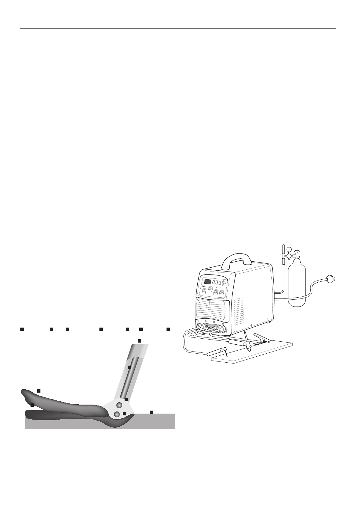
Arc length
To start the arc, the electrode should be gently scraped on the work
until the arc is established. There is a simple rule for the proper arc
length; it should be the shortest arc that gives a good surface to the
weld. An arc that is too long reduces penetration, produces spatter
and gives a rough surface finish to the weld. An excessively short
arc will cause sticking of the electrode and rough deposits that are
associated with slag inclusions.
For downhand welding, it will be found that an arc length not
greater than the diameter of the core wire will be most satisfactory.
Overhead welding requires a very short arc, so that a minimum
of metal will be lost. Certain SolidSTRIKE electrodes have been
specially designed for ‘touch’ welding. These electrodes may be
dragged along the work and a perfectly sound weld is produced.
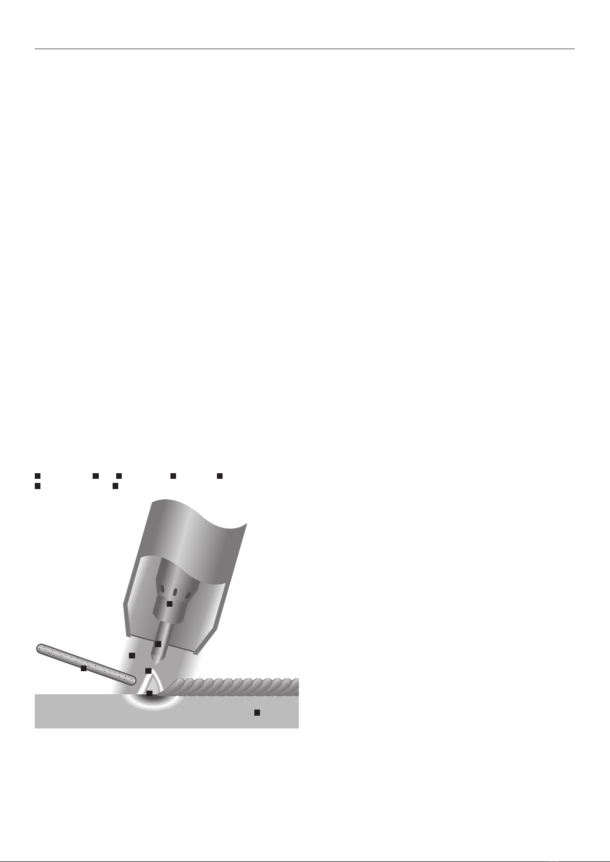
Electrode angle
The angle which the electrode makes with the work is important to
ensure a smooth, even transfer of metal. The recommended angles
for use in the various welding positions are covered later.
Correct travel speed
The electrode should be moved along in the direction of the joint
being welded at a speed that will give the size of run required. At
the same time the electrode is fed downwards to keep the correct
arc length at all times.
Correct travel speed for normal welding applications varies between
approximately 125–375 mm per minute, depending on electrode
size, size of run required and the amperage used.
Excessive travel speeds lead to poor fusion, lack of penetration, etc.
Whilst too slow a rate of travel will frequently lead to arc instability,
slag inclusions and poor mechanical properties.
3.4 Welding technique
Successful welding depends on the following factors:
• selection of the correct electrode
• selection of the correct size of the electrode for the job
• correct welding current
• correct arc length
• correct angle of electrode to work
• correct travel speed
• correct preparation of work to be welded.
3.5 Electrode selection
As a general rule the selection of an electrode is straight forward,
in that it is only a matter of selecting an electrode of similar
composition to the parent metal. It will be found, however, that for
some metals there is a choice of several electrodes, each of which
has particular properties to suit specific classes of work. Often, one
electrode in the group will be more suitable for general applications
due to its all round qualities.
Electrode size
The size of the electrode is generally dependent on the thickness
of the section being welded, and the larger the section the larger
the electrode required. In the case of light sheet the electrode size
used is generally slightly larger than the work being welded. This
means that if 1.5 mm sheet is being welded, 2.0 mm diameter
electrode is the recommended size. The following table gives the
recommended maximum size of electrodes that may be used for
various thicknesses of section.
Recommended electrode sizes
Average thickness of plate or
section
Maximum recommended
electrode diameter
≤1.5 mm 2.0 mm
1.5–2.0 mm 2.5 mm
2.0–5.0 mm 3.15 mm
5.0–8.0 mm 4.0 mm
≥8.0 mm 5.0 mm
For further help on choosing the right electrode for your work
please contact your local Messer supplier.
Welding current
Correct current selection for a particular job is an important factor in
arc welding. With the current set too low, difficulty is experienced
in striking and maintaining a stable arc. The electrode tends to stick
to the work, penetration is poor and beads with a distinct rounded
profile will be deposited.
Excessive current is accompanied by overheating of the electrode.
It will cause undercut, burning through of the material, and give
excessive spatter. Normal current for a particular job may be

014 TIG 185AC/DC FP Operating manual
Correct work preparation
The method of preparation of components to be welded will depend
on equipment available and relative costs. Methods may include
sawing, punching, shearing, lathe cut-offs, flame cutting and others.
In all cases edges should be prepared for the joints that suit the
application. The following section describes the various joint types
and areas of application.
3.6 Types of joints
This system is capable of several types of weld, from Butt through
to Fillet welds.

015TIG 185AC/DC FP Operating manual
Negative output terminal
Gas-electricity system output terminal
Torch/foot contol socket
Positive output terminal
4. Package contents.
Package contents
Power source
Work return lead
TIG torch
MMA electrode holder and cable
Gas hose
Operator’s manual
Foot control
Front Connections of TIG 185 AC/DC

016 TIG 185AC/DC FP Operating manual
5. TIG 185 AC/DC installation.
Installation for TIG setup
GAS
VRD
WARNING
Before installing please ensure that all the power is turned off.
Connect
the work return lead to the machine. Ensure that the work return
lead is firmly connected before connecting the power plug in to the
electrical output socket. Ensure free flow of air around machine to
avoid
overheating.
5.1 Installation for TIG setup
1. Connect one end of the work return lead to positive of the
front panel, and fasten it clockwise. Connect the other end of the
clamp to the work piece.
2. Connect the gas cylinder to the regulator. Select correct shielding
gas for the application.
3. Connect the dinse plug of the TIG torch to negative of the
front panel, and fasten it clockwise.
4. Connect securely the gas lead of the TIG torch to the gas output
terminal .
5. Connect the 5-pin plug of the TIG torch to the Torch/foot contol
socket and fasten the screw.
Installation for TIG setup using foot control
GAS
VRD
MAX
MI N
5.2 Installation for TIG setup with optional foot
control
1. Connect one end of the work return lead to positive of the
front panel, and fasten it clockwise. Connect the other end of the
clamp to the work piece.
2. Connect the gas cylinder to the regulator. Select correct shielding
gas for the application.
3. Connect the dinse plug of the TIG torch to negative of the
front panel, and fasten it clockwise.
4. Connect securely the gas lead of the TIG torch to the gas output
terminal .
5. Connect the electical lead of the foot control to the 5-pin Torch/
foot contol socket and fasten the screw.
6. The 5-pin plug of the TIG torch should now hang free.
Installation for MMA process
GAS
VRD
5.3 Installation for MMA process
1. Connect the work return lead into the negative of the machine
and fasten it clockwise.
2. Connect the electrode holder to the positive of the machine
and fasten it clockwise tightly.
3. Please note that for manual metal arc (MMA) welding the
electrode holder can be switched to the negative pole of the
welding machine if so required by the specification of the
electrode.

017TIG 185AC/DC FP Operating manual
4. With the AC balance adjustment set at 20%, higher currents
can be used on thinner electrodes, resulting in the use of smaller
gas cups, therefore increasing visibility and reducing gas flows.
5. Down slope adjustment. Down-slope adjustment allows a
gradual decrease in amperage at the end of the weld to improve
crater control.
6. Post flow adjustment. Allows a variable flow of shielding gas
after current has been switched off to ensure that no oxidation of
both the tungsten and the weld pool happens.
7. Welding current adjustment. When switched to MMA function
only the current control knob is active.
6.3 Indicator function
1. Over-heat protection indicator. This indicator will illuminate
when the duty cycle of the machine has been exceeded. The
machine will normally reset itself after 2-3 minutes.
2. Over-current protection indicator. This indicator will illuminate
when an accidental over-current has occurred.
3. VRD indicator. This indicator will illuminate when useing MMA
mode.
4. Foot control indicator. This indicator will illuminate when foot
control is in use.
Control Panel of TIG 185 AC/DC
6.1 Function switches
1. AC/DC switch. AC switch intended for aluminium. DC position
is for all other materials.
2. 2T/4T switch (trigger latching). This special feature allows the
operator to relax the trigger after first depressing it, the gas
shielding to start before the welding commences. This feature
is of particular importance as it ensures that the weld will have
adequate gas shielding to eliminate the risk of oxidisation
(contaminants) causing a defective weld. (Remember, a defective
weld may not be detected by a visual inspection.)
3. MMA/TIG switch. Allows you to switch between TIG and MMA
welding.
4. Frequency switch. Changes the pulse frequency.
6.2 Adjustment knobs
1. Welding current adjustment. Adjusts welding current.
2. AC balance adjustment. In addition to increasing the welding
current in AC applications, a change in the penetration or
cleaning when welding can be achieved by adjusting the AC
Balance.
3. The AC balance (time spend in the positive (maximum cleaning)
or negative (maximum penetration) can be adjusted by using
the AC balance adjustment. By adjusting the AC balance
adjustment from 20-100% progressively increases the time in
the positive side of the AC curve (higher heat concentration in
the non-consumable tungsten electrode). This has the result that
the amount of penetration is decreased.
6. Control panel.
VRD
Frequency switch
Over-heat
protection indicator
MMA/TIG switch
Over-current
protection indicator
AC/DC switch
Welding current adjustment
AC balance adjustment
2T/4T switch
Down slope adjustment
VRD indicator
Current meter
Post flow adjustment
Foot control indicator

018 TIG 185AC/DC FP Operating manual
7. TIG 185 AC/DC operation.
WARNING
Do not connect or disconnect the machine cables whilst welding as
this
may cause serious harm to yourself and/or the machine.
7.1 Operation for AC welding
1. Refer to section 5.1 for how to connect torch
2. Switch MMA/TIG switch to TIG
3. Set the AC/DC switch to AC
4. Turn on power switch on the rear of machine (fan will operate
continuously)
5. Turn on shielding gas and regulate gas flow to specified flow rate
6. Select the AC balance control based on the degree of cleaning
of the base material that is required
7. The post flow can be regulated by adjusting the post flow
adjustment
8. Press the contactor switch on the welding torch to start up
the electromagnetic valve. The sound of the high frequency
spark discharge in the welding machine will be audible and the
shielding gas will flow
7.2 Operation for DC welding
1. Switch MMA/TIG switch to TIG
2. Set the AC/DC switch to DC
3. Turn on power switch on the rear of machine (fan will operate
continuously)
4. Turn on shielding gas and regulate gas flow to specified flow rate
5. The post flow can be regulated by adjusting the post flow
adjustment
6. Press the contactor switch on the welding torch to start up
the electromagnetic valve. The sound of the high frequency
spark discharge in the welding machine will be audible and the
shielding gas will flow
7.3 Operation for foot control (TIG welding only)
1. Ensure the foot pedal is correctly installed as described in 5.2.
The foot control indicator light will illuminate when the foot pedal
is in use.
2. Switch MMA/TIG switch to TIG
3. Turn on power switch on the rear of machine (fan will operate
continuously)
4. Turn on shielding gas and regulate gas flow to specified flow rate
5. The post flow can be regulated by adjusting the post flow
adjustment
6. Press the foot control pedal to start up the electromagnetic
valve. The sound of the high frequency spark discharge in the
welding machine will be audible and the shielding gas will flow
7. Step on the foot switch for remote control. The minimum and
maximum current can be set by the two dials on the side. These
dials control the percentage of the welding current that has
been selected on the machine. e.g. if you set the current on the
machine to 100 and you turn the ’max’ dial half way then the
current will not exceed 50.
7.4 Operation for MMA welding
1. Switch MMA/TIG switch to MMA. When using MMA function
the VRD light will illumate.
2. Turn on power switch (fan will operate continuously)
3. Select proper welding current according to the electrode
manufacturer’s specification

019TIG 185AC/DC FP Operating manual
8. Technical specifications.
Specifications SMAW TIG
Model no. TIG185ACDC TIG185ACDC
Power voltage AC Single phase 230 V ±15% Single phase 230 V ±15%
Frequency 50/60 Hz 50/60 Hz
Rated input current 30.6A 32.3A
Output current 10 to 135 A 10 to 180 A
Rated working voltage 25.4 V 17.2 V
No-load voltage 62 V 62 V
Duty cycle 35% at 135 A 30% at 180 A
Arc initiation HF HF
Remote control NO NO
Efficiency 80 % 80 %
Power factor 0.73 0.73
Insulation grade F F
Housing protection grade IP21 IP21
Dimensions L x W x H 465 × 202 × 390mm 465 × 202 × 390mm
Weight 14.7 kg 14.7 kg
Standards CAN/CSA-E60974-1 CAN/CSA-E60974-1

020 TIG 185AC/DC FP Operating manual
9. Troubleshooting guide.
Problem Cause Solution
Excessive electrode
consumption
Inadequate gas flow Increase gas flow
Inadequate post gas flow Increase post flow time to 1 sec per 10 amps
Improper size electrode for current required Use larger electrode
Operating of reverse polarity Use larger electrode or change polarity
Electrode contamination Remove contaminated portion, then prepare again
Excessive heating inside torch Replace collet. Try wedge collet or reverse collet
Electrode oxidising during cooling Increase downslope
Shield gas incorrect Change to Argon (no oxygen or CO₂)
Erratic arc Incorrect voltage (arc too long) Maintain short arc length
Current too low for electrode size Use smaller electrode or increase current
Electrode contaminated Remove contaminated portion, then prepare again
Joint too narrow Open joint groove
Contaminated shield gas. Dark stains on the electrode
or weld bead indicate contamination
The most common cause is moisture or aspirated air
in gas stream. Use welding grade gas only. Find the
source of the contamination and eliminate it promptly
Base metal is oxidised, dirty or oily Use appropriate chemical cleaners, wire brush, or
abrasives prior to welding
Inclusion of
tungsten or oxides
in weld
Excessive current for tungsten size used Reduce the current or use larger electrode
Accidental contact of electrode with puddle Maintain proper arc length
Accidental contact of electrode to filler rod Maintain a distance between electrode and filler metal
Using excessive electrode extension Reduce the electrode extension to recommended limits
Inadequate shielding or excessive drafts Increase gas flow, shield arc from wind, or use gas lens
Wrong gas Do not use ArO₂ or ArCO₂ GMAW (MIG) gases for TIG
welding
Heavy surface oxides not being removed Use wire brush and clean the weld joint prior to welding
Table of contents
Popular Welding System manuals by other brands

EWM
EWM Tetrix 352 AC/DC SYNERGIC PL. AW GR operating instructions

iWeld
iWeld ARC 150 MINI user manual

Miller Electric
Miller Electric MOG-200C owner's manual

Hypertherm
Hypertherm Powermax 900 installation manual

Miller
Miller SQUAREWAVE 1000 owner's manual

FRONIUS
FRONIUS PullMig AL216 operating instructions