Youly Electric YL Powership MMA-250FI User manual

1
Operator’s Manual
MMA-160FI MMA-250FI
Inverter DC MMA Welder
IMPORTANT: This operational manual kindly show you how to install, dedug,
operate and maintain the welder. Read this instructions carefully and you will
understand how to use it to reduce the risk of error operation.
Warning!
This machine should be operated and maintained by full-time staffs or
professionals. You are not allowed to operate and repair it unless read this manual

2
CONTENT
1 Brief Introduction ----------------------------------------------------------------------------------------- 3
2 Safety --------------------------------------------------------------------------------------------------------- 3
2.1 Self-Protection --------------------------------------------------------------------------------------------- 3
2.2 Cautions ---------------------------------------------------------------------------------------------------- 4
2.3 Safety Precaution for Installation and Location ------------------------------------------------------ 4
2.4 Security Check -------------------------------------------------------------------------------------------- 5
3 Technical Description ------------------------------------------------------------------------------------- 5
3.1 Environment ----------------------------------------------------------------------------------------------- 5
3.2 Input Power ------------------------------------------------------------------------------------------------ 6
3.3 Equipment Principle -------------------------------------------------------------------------------------- 6
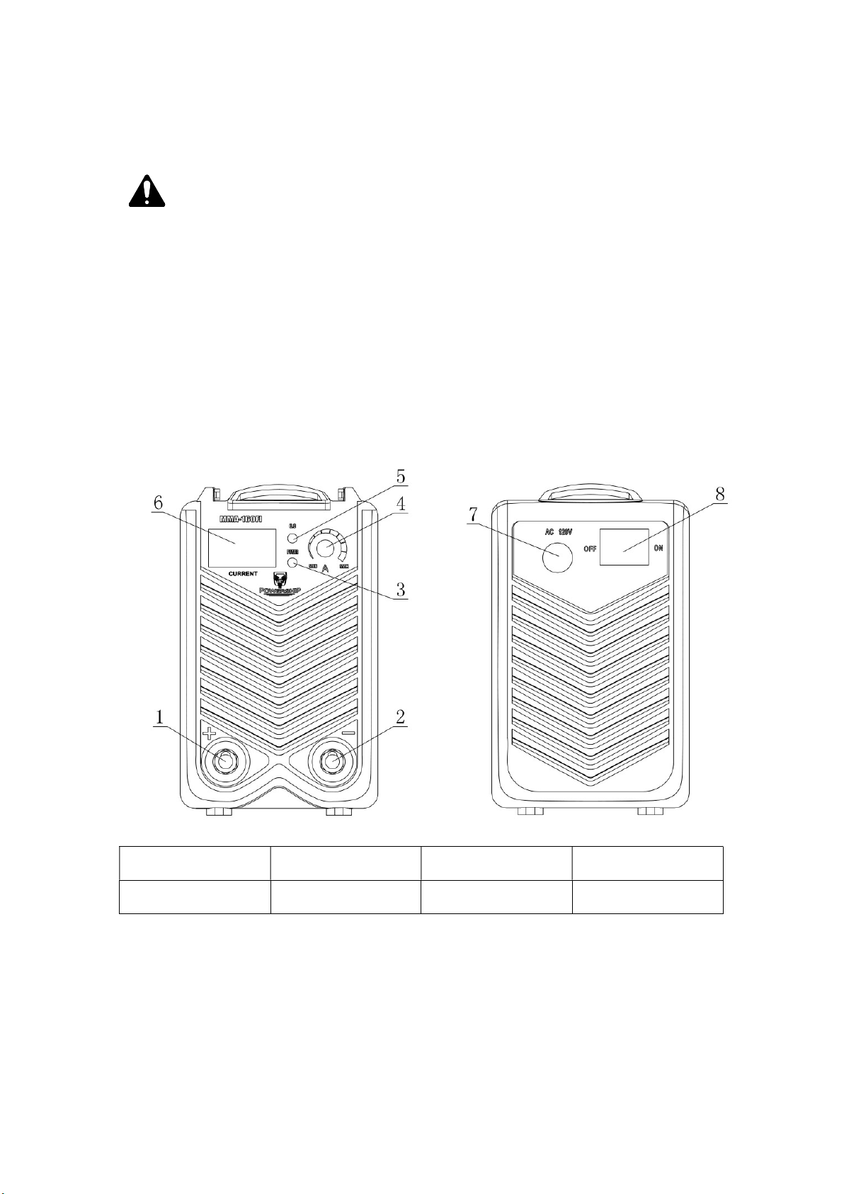
3.4 Equipment Structure -------------------------------------------------------------------------------------- 6
3.5 Guide for Marking Models ------------------------------------------------------------------------------ 7
3.6 Parameter --------------------------------------------------------------------------------------------------- 7
3.7 Standard ---------------------------------------------------------------------------------------------------- 8
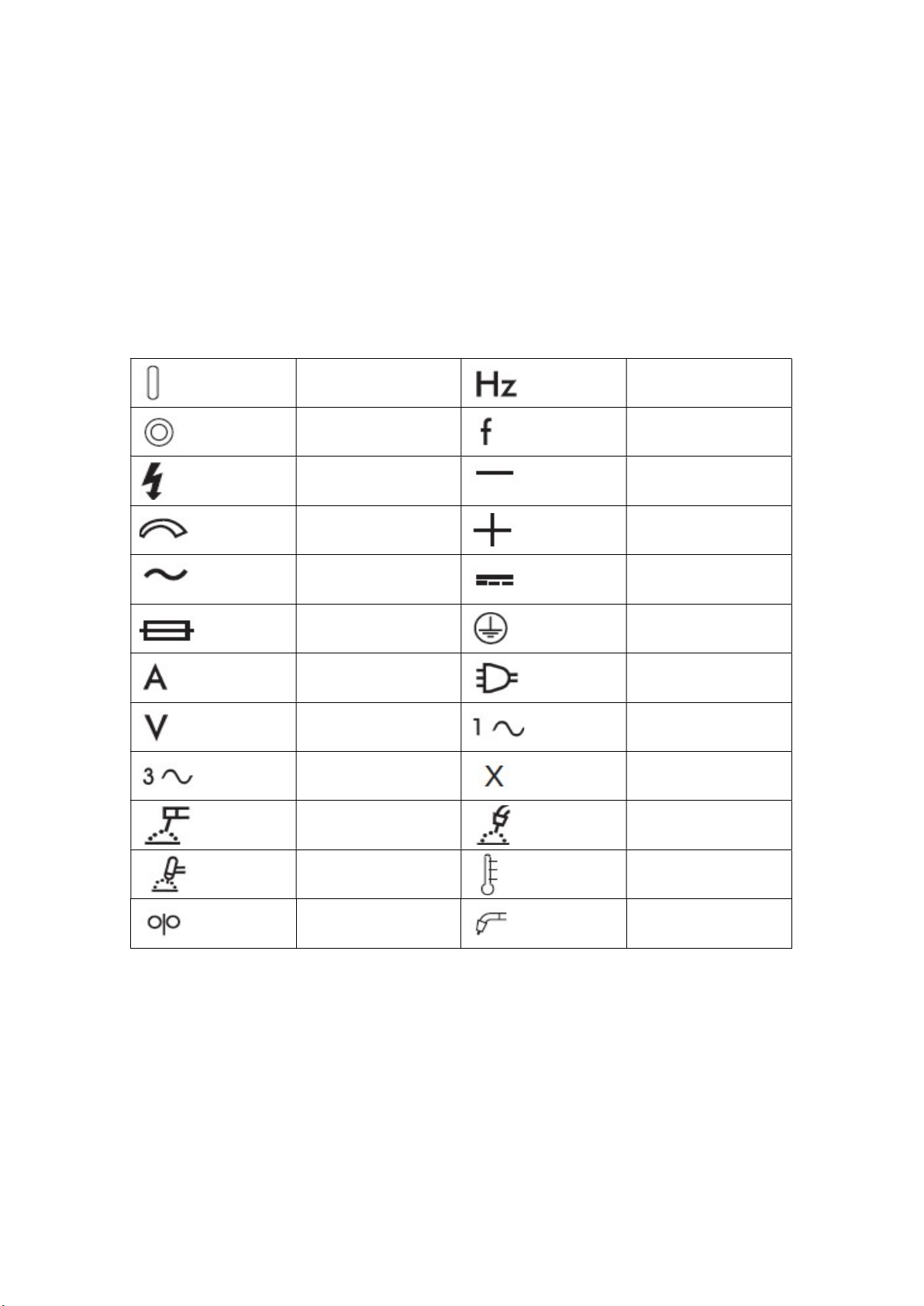
3.8 Symbol Chart ---------------------------------------------------------------------------------------------- 8
4 Installation -------------------------------------------------------------------------------------------------- 8
4.1 Connection ------------------------------------------------------------------------------------------------- 8
4.2 Power Source Connection ------------------------------------------------------------------------------ 9
4.3 Electrode Polarity ---------------------------------------------------------------------------------------- 9
4.4 Workpiece Connection ---------------------------------------------------------------------------------- 10
5 Operation Instruction ----------------------------------------------------------------------------------- 10
5.1 Procedure ------------------------------------------------------------------------------------------------- 11
5.2 Electrode Replacement --------------------------------------------------------------------------------- 11
5.3 Slag Removal -------------------------------------------------------------------------------------------- 12
5.4 Maintenance ---------------------------------------------------------------------------------------------- 12
6 Basic Trouble Shooting ---------------------------------------------------------------------------------- 13
7 Parts List --------------------------------------------------------------------------------------------------- 14
8 Interconnection Diagram ------------------------------------------------------------------------------- 15
9 Accessories ------------------------------------------------------------------------------------------------- 15
10 Transportation and Storage -------------------------------------------------------------------------- 16
11 Quality Warranty --------------------------------------------------------------------------------------- 16

3
1 Brief Introduction
INARC welder uses imported IGBT as main electric components. It is supplemented by a
specially developed main PCB board. In addition, the uniform regulation of welding
current has been designed to guarantee the arc reach good welding process adaptability.
What’s more, its perfect dynamic protection features ensure that it is safe and reliable
when use. It is ideal for using low carbon steel, alloy steel etc.
INARC Features:
60% high duty cycle.
Lower cost operation, more portable, more compact, superior output.
Excellent arc properties and solution droplet transfer.
With the protections of over-heating, over-current.
Digital display function.
Plastic handle makes it beautiful and easy to carry.
Convenient quick connection for the output makes it quick, safe, simple and stable.
NOTES: The above description may be modified without prior notice such as
omissions, unclear statements about this welder.
2 Safety
2.1 Self-Protection
* The user must comply with occupational safety and health rules and wear appropriate
labor protective equipment. Try to avoid injury on eye and skin.
* It is safe to cover your head with face mask while welding, only do the observation on
the arc through the window of the mask.
* Don’t expose any part of the body at the same time to the welding positive and negative
output terminals without insulated protection.

4
2.2 Cautions
* INARC Inverter DC Arc welder is a kind of electronic product which makes its
components more easily damaged. While replacing or modulating, the strength should
not be too much in order to avoid causing damage to the device.
* Check the connection to see if it is correct or reliable each time before working.
Besides, ensure the grounding outlet device correct.
* While using, as smoke is harmful to human’s health, the operation must be carried out
in the ventilation and exhaust facilities.
* Prohibit non-professionals to change or replace the welder.
* Since the welder owns strong electromagnetic and radio frequencies, the people with
cardiac pacemakers affected by the interference electromagnetic, electrical frequency are
not allowed to stay nearby.
* When it works, please pay attention to its rated duty cycle. Do not overload.
2.3 Safety Precaution for Installation and Location
* In some areas, where something may fall from the sky, personal safety precaution
should be taken.
* In some areas around construction site, something like the dust, acid, corrosive gases or
other substance in the air cannot exceed the standard value except those generated while
welding.
* It is should be equipped in the open air where there is no direct sunlight, anti-rain,
temperature range from -10℃ to +40℃ and low humidity place.
* 50cm space is needed to ensure good ventilation.
* No metal impurities are tolerant inside the welder.
* In some areas, there is no severe vibration.
* Make sure no interference will be caused to the surrounding in the welding area.
* Whether the power supply capacity is sufficient to allow the welder to work normally
or not. And a safety protection device should be equipped in the input power.
* Prevent it from dumping if the welder is put in the place of over 10°incline.

5
2.4 Security Check
The following items must be checked up by the operator each time before access to the
power source.
* Make sure the power socket is reliably grounded.
* Make sure the output terminals are well connected without short circuit.
* Make sure output and input cables are perfect with no exposure.
The welding machine must be inspected by professionals at regular time (not exceed 6
months). The contents as follow:
* Whether the electronic components are loosed or not and dust removal must be
conducted.
* Whether the panel mounted on the device should be able to guarantee the normal
implementation of the machine.
* Whether the input cables are damaged or not. If yes, safe handling must done.
Warning!
Disconnect the power source before servicing it. Contact with the manufacturer or
agent immediately to acquire the service and support skills when users do not have
the ability to repair it.
3 Technical Description
3.1 Environment
* Working temperature: -10℃~40℃.
* Transportation and storage: -25℃~55℃.
* Relative air humidity: 40℃≤50%; 20℃≤90%.
* The dust, acids, corrosive gases and substance in the ambient air must be lower normal
level except those from welding process.
* Altitude must be less than 1km.
* Keep good ventilation at a distance of 50cm around.
* Put it in somewhere the speed of wind not less than 1m/s.

6
3.2 Input Power
* Power supply waveform should be sine wave and frequency fluctuations with less than
±1% of its rating.
* The fluctuations of input voltage must be lower than ±10% of the rated value.
3.3 Equipment Principle
NOTES: This is inverter technology. The main part as follow:
Rectifier Filter IGBT Transformer Rectifier Choke
3.4 Equipment Structure
The INARC Inverter DC MMA Welder uses portable cabinet structure: the upper part of
front panel has been equipped with welding current adjustment knob, power indicator
(green), abnormal indicator (yellow). The output terminal is fitted with quick connector
both “+” and “-”. The back panel owns power switch, motor fan, input power cable. The
inside body of the machine includes PCB main board, electronic components, radiator
etc.

7
3.5 Guide for Marking Models
IN ARC AMP
It means INARC-150 is an Inverter MMA (Manual Arc Welding) welding machine and
its rated output current can reach 150A.
3.6 Parameter
Item/Model MMA-160FI MMA-250FI
Rated Input Voltage (V) 120 ±10% 120 ±10%
Frequency (Hz) 50/60 50/60
Rated Input Capacity (KW)
4.56 5.32
Rated Input Current (A) 21.9 30.5
Rated Duty Cycle 60% @ 115A 60% @ 135A
No Load Voltage (V) 56 56
Output Current Range (A) 20~115 20~135
Efficiency (%) 85 85
Electrode Size (mm) 1.5-3.2 1.5-3.2
Cooling Type AF AF
Overall Dimension (INCH)
15.4*4.88*9.29 15.4*4.88*9.29
Gross Weight (LBS) 10.74 10.74
INVERTER
MMA
Rated Output Welding Current

8
3.7 Standard
* EN 60917-1: Arc Welding Machine Standards
* JB / T 7824-95: Technical Conditions of Inverter Arc Welding Rectifier
* GB 4208-93: Protection Class (IP Code)
3.8 Symbol Chart
Note that only some of these symbols will appear on your model.
On
Hertz (cycles / sec)
Off
Frequency
Dangerous Voltage Negative
Increase / Decrease
Positive
AC Auxiliary Power Direct Current (DC)
Fuse
Protective Earth
Amperage
Line
Voltage
Single Phase
Three Phase Duty Cycle
SMAW
GMAW
GTAW
High Temperature
Wire Feed Function
Welding Gun
4 Installation
4.1 Connection
* The welder should be placed in dry and no dusty surrounding where there is no
corrosive chemicals, flammable, explosive gases.

9
* Avoid direct sunlight and rain. And maintain the ambient temperature ranging from
-10℃ to 40℃.
* The space of 50cm should be left around the equipment.
* If indoor ventilation is not good enough, the ventilation exhaust device should be
installed.
4.2 Power Source Connection
Access the back panel (power source cable) to the power supply which is equipped with
circuit breakers and grounding line (grid), and it is strictly prohibited that ground wire is
connected to the grid, otherwise bear your own consequences.
4.3 Electrode Polarity (see above picture)
Connect the quick plug with electrode holder to the negative terminal and then tightened
them up clockwise.
Installation Diagram

10
4.4 Workpiece Connection
Connect the quick plug with earth clamp to the positive terminal on the front panel below.
And then tighten them up. Access the earth clamp to the workpiece.
Warning!
It is forbidden to connect the workpiece to the welder with iron or other poor
conductors.
5 Operation Instruction
NOTES: Finger or round bars especially metal rod must be less than 12.5mm and it
can not be inserted into the welder. Also you can not press it heavily.
1 Positive Terminal 2 Negative Terminal 3 Power Indicator 4 Knob
5 Abnormal Indicator 6 Digital Display 7 Power Cable 8 Switch
NOTES: When the welder works for a long time, the high temperature indicator
will light. This means the inside temperature has exceeded its standard. The
machine will stop, it is normal, after a little time cooling, the machine can recover
the work automatically.

11
* You have to wear canvas overalls and face mask to prevent from arc light and heat
radiation.
* Vibration screen should be laid out to prevent others from arc light.
* Inflammable and explosive stuffs are not allowed to pile up. All the connections must
be right, reliable.
5.1 Procedure
a) Connect to the power switch digital ammeter lights on.
b) To adjust the current potentiometer to the required value of the welding.
c) Pick up electrode holder, and point at the welding edge. Then put the electrode on the
workpiece, you can start welding.
5.2 Electrode Replacement
When the electrode is left only 2~3cm away from the holder, you have to replace new
one to go on working.
NOTES: When the electrodes combustion is in process at high heat, do not touch it
with bare hands while replacing it. Besides, the electrode head down should be
unified in a metal container. And the cover coating should not be caught by the
holder. Scratch gently when igniting the arc, otherwise it is easy to come across the
phenomenon of sticking electrode.
5.3 Slag Removal
After finishing work, you should remove the slag with specific knock residue tools in the
way of knocking.
Warning!
The welding slag should not be removed until it is cooled down. Don’t point it at the
other people while knocking on the slag incase that it will do harm with pop-up slag.

12
5.4 Maintenance
* The major difference between inverter arc welder and traditional welder is the inverter
welder has lots of advanced electronic components. What’s more, it is high technology
product. And this requires high skill maintenance.
* It is very essential to do daily maintenance. You must be responsible for examination
and repair. Once you do not have the ability to check it, kindly contact with manufacturer
to acquire the service and support of technology.
The following is the steps for maintaining:
a) Dust removal.
b) Remove dust by professionals with dry and clean compressed air (using a compressor
or Paper Tiger) regularly. Meanwhile, check inter circuit of welding machine regularly
and make sure the cable is connected correctly and connectors are connected tightly. If
scale and loose are found, please give a good polish to them. Then connect them again
tightly. Generally, if welding machine is operating in environment where there is no
heavy accumulated dust, the machine need remove dust once a year. If in the
environment where is polluted with smokes and polluted air, it is needed to be removed
once or even twice of each season.
c) To maintain good contact with cable and plugs.
d) Check up the contact conditions of cable and plug frequently, at least once a month for
stationary use.
Warning!
Due to high voltage in the main circuit of the welder, you need to do the safety
precaution measure to prevent accidental electric shock. Don’t open the shell except
for the professionals. Remember to turn off the power before removing dust. And
don’t meddle with the connections and components when doing this work.

13
6 Basic Trouble Shooting
No. Description Possible Cause Remedy
1 Abnormal indicator Bad ventilation leads to
overheating protection
Improve ventilation
conditions
High environmental
temperature
Automatic recovery
after decreasing
Exceed rated duty cycle Replace potentiometer
2 Current knob broken Potentiometer damaged Replace it
3 Motor fan can’t work or low
rotational speed
Bad power switch Replace the switch
Bad fan Replace the fan
Led broken Check the circuit
4 No open circuit voltage Overheating See point 1
Bad power switch Replace the switch
5 Electrode holder cable is too
hot; output terminals are too
hot.
Capacity on electrode
holder is too small
Replace larger capacity
electrode holder
Cable is too thin Replace a proper cable
Socket is loosen Remove the oxide coat
and re-tight it
6 Power off Power capacity is not big
enough
Enlarge the capacity
Welding process Contact the supplier
7 Other problems Contact the supplier
Warning!
The machine has the function of prohibit switching power supply in rapid
succession within a short period of time for switching on and off. The power will not
open then (the indicator light is not on or the fan does not work or there is no-load
voltage). Shut down the power switch and resume back to normal after a few
minutes.

14
7 Parts List
NOTES: The above components listed are just for your reference. If something
different with the real machine, kindly follow the real one.

15
8 Interconnection Diagram
9 Accessories
No. Description Qty.
1 INARC Welder 1set
2 Operator’s Manual 1pc
3 Electrode Holder 1pc
4 Earth Clamp 1pc
5 Brush & Hammer 1pc
NOTES: All above mentioned are based on the ordering contact unless otherwise
agreed by the parties.
Circuit Schematic of INARC Welder
(Figures for reference are subject to change without notice.)

16
10 Transportation and Storage
* This machine is an indoor equipment and the attacks of rain and snow should be
avoided in the process of transportation and storage. While loading and unloading, more
attention should be paid on the package with words of warning. Storage warehouse
should be kept dry with good air circulation and no corrosive gas or dust. The
temperature should be maintained from 25℃ to 55℃ and relative humidity must be
lower than 90%.
* If the products are still needed to continue storing after stripping, repacking should be
carried out according to original package’s requirement. Remember before storage, don’t
forget to clean and seal it with plastic bags.
* Users should maintain the cartons and shock blocks in order to be properly packaged in
need of long distant transportation. For the long distant transportation, it should be
retrofitted with a wooden case and mark the “up” or “rain” symbols.
11 Quality Warranty
If the machine is used in accordance with the regulations on the operation manual, in
compliance with the rules on installation, storage, use, maintenance, safeguarding,
manufacturers should provide free services for the users under the conditions of within 12
months from the date of purchase (based on the issued invoice date).
This manual suits for next models
1
Table of contents
Popular Welding System manuals by other brands

Lincoln Electric
Lincoln Electric Idealarc DC-1500 Operator's manual

GYS
GYS 031531 manual

Lincoln
Lincoln INVERTEC V350-PRO CE Operator's manual

Longevity
Longevity WeldAll 160 operating manual

Air Liquide
Air Liquide Oerlikon CITOCUT 25C Safety instruction for use and maintenance

Kemppi
Kemppi ArcValidator operating manual