Metabolic Devices Moonwalker User manual
metabolic devices

metabolic devices
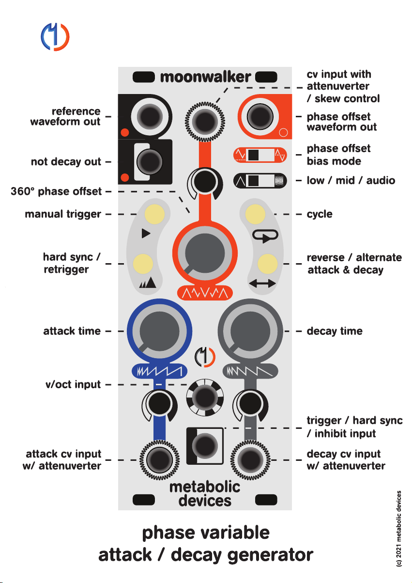
Figure 1a shows how phase offset affects the phase offset output in
unipolar and bipolar modes, as well as the reference waveform output
Figure 1b shows how phase offset affects the outputs when attack and
decay rates are not equal.
Figure 2 shows how inhibit affects the output

Moonwalker is an extremely flexible signal generator that can act as an
envelope generator, LFO, or audio oscillator. Perhaps the most uniquely
defining characteristic of Moonwalker is the Phase Offset parameter
which moves the start and end of the waveform to any point in the cycle.
There are however a number of other unique features that set it apart.
This manual starts by covering the basics of how to use Moonwalker in
the 3 most common configurations. We’ll then dive in to Phase Offset,
explaining what it does and how to use it. Finally we’ll discuss some
advanced use cases that really exploit the feature set.
For the purposes of these sections Phase Offset will not be discussed
and as such the output can be taken from either the Phase Offset or the
Reference outputs without any notable difference. Be aware that once
phase offset has been adjusted to anything other than null, the outputs
are not the same. The differences will be discussed in detail later in the
section on phase offset.
Moonwalker as an envelope:
When Moonwalker is first turned on it is in one-shot mode as used when
generating envelopes, so let’s start here. For envelopes, set mid or low
frequency range active, Phase Offset output mode to unipolar, and plug
a trigger source into the trigger input. Start with the phase offset at mini-
mum and it’s cv attenuverter to 12:00, patch the phase offset output to
the destination of choice, and set attack and decay times to taste.
NOTE: it is very important to null the phase offset cv attenuverter
even if nothing is plugged into it! There is a powerful feature here that
can lead to confusing behavior during the learning process. When in
doubt, plug a cable into the cv input jack with the other end floating or
grounded (0v). We’ll discuss this feature in detail later.
Use the
Attack
knob to set how long it takes to go from 0v to 10v. A posi-
tive voltage at the Attack cv input will increase the attack time, while a
negative voltage will decrease it. The amount of modulation can be atten-
uated or attenuated & inverted using the cv attenuverter.

The
Reverse / Alternate Attack & Decay
button provides a handy
way to audition how an envelope would sound with the attack and decay
times swapped. When the led is on, the Attack controls are now assigned
to Decay, and the Decay controls are now assigned to Attack. When
alternating, Moonwalker will generate the envelope with Attack & Decay
rates as normal, and then swap them when the next trigger is received.
They are returned to normal on the next trigger, and the pattern contin-
ues to alternate between normal and swapped as long as this mode is
enabled. A short button press enables reverse, and a long press enables
the alternating mode. Button presses take effect on the next trigger so
as not to interrupt playback.
The
Not Decay
output goes to +5v when Moonwalker is not in the decay
segment of the Reference Output. This includes the time when Moon-
Use the
Decay
knob to set how long it takes to go from 10v to 0v. A posi-
tive voltage at the Decay cv input will increase the decay time, while a
negative voltage will decrease it. The amount of modulation can be atten-
uated or attenuated & inverted using the cv attenuverter.
Plug a trigger source into the
Trigger Input
on Moonwalker, or if you
don’t have a trigger source ready you can use the Manual button on
Moonwalker to trigger it. Once it has been triggered, Moonwalker will
ignore additional triggers until it completes it’s cycle. This can be very
handy for deriving slow moving events from a master clock and works like
a clock divider based on absolute time rather than number of clock
pulses.
If the
Retrigger
button is enabled Moonwalker will react to all incoming
triggers, resetting the envelope to the starting amplitude each time a trig-
ger is received. Enable this when you want Moonwalker to be more active,
and to cut off longer notes when a new note happens before the old one
is finished.
The
Volt Per Octave
input can be used to modulate both attack and
decay at the same time and change the overall frequency. A typical patch
would take the v/oct that drives the vco here, so that higher pitches have
shorter envelopes while lower notes are longer.

Just as in envelope mode, a trigger in the
Trigger input
with
Retrigger
enabled will reset Moonwalker to the beginning amplitude. This allows
Moonwalker to be synchronized with an external clock regardless of the
frequency it’s running at. A slower clock that syncs Moonwalker every
bar or two can be a cool way to give some form to an LFO that is at a
different tempo than the clock. Synchronizing it every bar or two creates
a recognizable pattern out of what would otherwise be an unrelated free
running LFO.
Without Retrigger enabled, the
Trigger Input
now pays attention to how
long the input is held high. A gate in the trigger input will
Inhibit
the LFO
as long as the pulse is high. Inhibit drives the waveform in a direction
and at a rate determined by the attack / decay rates.
walker is inactive, so it goes high after decay is finished and stays high
during steady state and until attack is finished. It is at 0v during decay. It
can be used as a logic source to enable effects or routing during only a
portion of the event. It can also be used to chain multiple Moonwalkers
to create very complex envelopes.
Moonwalker as an LFO:
Tap the
Cycle
button to use Moonwalker as a low frequency oscillator.
Use the
Attack
knob to set how long it takes to go from 0v to 10v. A pos-
itive voltage at the Attack cv input will increase the attack time, while a
negative voltage will decrease it. The amount of modulation can be
attenuated or attenuated & inverted using the cv attenuverter.
Use the
Decay
knob to set how long it takes to go from 10v to 0v. A posi-
tive voltage at the Decay cv input will increase the decay time, while a
negative voltage will decrease it. The amount of modulation can be
attenuated or attenuated & inverted using the cv attenuverter.
The
Volt Per Octave input
can be used to modulate both attack and
decay at the same time and change the overall frequency. The response
here is inverted to that of the attack and decay inputs, meaning that a
positive voltage will increase the frequency while a negative voltage will
decrease it.

The
Reverse / Alternate Attack & Decay
button provides a handy
way to audition how an LFO would sound with the attack and decay
times swapped. When the led is on, the Attack controls are now assigned
to Decay, and the Decay controls are now assigned to Attack. When
alternating, Moonwalker will generate the envelope with Attack & Decay
times as normal, and then swap them on the next cycle. They are
returned to normal on the next cycle, and the pattern continues to alter-
nate between normal and swapped as long as this mode is enabled. As
a free running LFO, alternating mode effectively makes Attack & Decay
frequency controls for two consecutive waveforms. A short button press
enables reverse, and a long press enables the alternating mode. Button
presses take effect on the next trigger so as not to interrupt playback.
The
Not Decay Output
is the pulse wave output of Moonwalker so it
provides a hard edge switching LFO signal rather than the sloped LFO
available at the Reference and Phase Offset outputs. It goes to +5v when
Moonwalker is in the attack segment of the Reference Output and to 0v
during decay.
The
Manual Trigger
button can be used to activate
Inhibit
when a trig-
ger source is not available.
In the top part of the Attack / Decay range, the
Inhibit
rate is relatively
fast and moves towards 0v where it will hold until the inhibit pulse goes
low. In the middle of the range it will move very slowly in either direction
and will look like plateaus in the waveform. In the lower part of the range
it will move towards 10v and the effect is lessened because we are
already at the end of the range.
Activating
Inhibit
is a great way to add complexity and interest to a
repeating LFO. To get stepped waveforms, drive inhibit with the pulse out
from another LFO and set it’s width to very wide. Set the Moonwalker
frequency fairly fast, but set the other LFO 3 or 4 times faster. Sync the
other LFO using the Not Decay out from Moonwalker to get a consistent
number of steps for every cycle and start them at the same time. If you
modulate the frequency of both LFO’s using their v/oct inputs, the
number of pulses per cycle stays consistent.

A trigger in the
Trigger Input
with
Hard Sync
enabled will reset Moon-
walker to the beginning amplitude. Syncing Moonwalker to another VCO
in this way can create additional harmonics for a brighter sound. Be sure
and patch the volt per octave to both modules if you want to keep the
shape and amplitude the same for different frequencies.
With
Hard Sync disabled
, the
Trigger Input
now becomes a gate
input that carves into the waveform for added harmonic complexity. A
pulse in the Trigger Input will
Inhibit
Moonwalker as long as the pulse
is high. Inhibit will drive the waveform in a direction and at a rate deter-
mined by Moonwalker’s frequency.
In the top part of the frequency range, the inhibit rate is relatively fast
and moves towards 0v like a reversal in direction. In the middle of the
frequency range it will move very slow in either direction and will look
like plateaus in the waveform. In the lower part of the range it will move
towards 10v and the effect is lessened because we are already at the
end of the range. Experimentation with the relative frequency and pulse
width of the pulse source is encouraged.
Moonwalker as an Audio VCO:
If we now switch our frequency range to audio, Moonwalker is ready to
be used as an audio source.
The
Attack and Decay knob range
is limited from about 750Hz to
20Hz to provide increased resolution for tuning, in light of the absence
of a fine tune control. Moonwalker can still generate frequencies across
the entire audio range, however it must be driven through the volt per
octave input.
Set the frequency and shape of the waveform using the Attack and
Decay controls. Modulation of Attack and Decay work just like in the
other modes, however modulation of the
Volt Per Octave
input should
be used by those concerned with staying in tune. A positive voltage at
the volt per octave input will increase the frequency while a negative volt-
age will decrease it.
Moonwalker tracks pitch accurately from roughly 5kHz to 15Hz.

Phase Offset:
Now that we’re familar with how to set up Moonwalker in the most
common ways, let’s take a closer look at the Phase Offset parameter.
Phase defines where in the cycle the envelope / oscillator starts and
ends, or more specifically it defines the start / end amplitude and direc-
tion of travel.
Imagine our waveform is sitting on a table exactly it’s size. We are going
to push the waveform over the edge of the table and as soon as any mol-
ecule passes the edge of the table, it is instantly transported to the
beginning of the table.
To get stepped waveforms, drive inhibit with the pulse out from another
VCO. Set it’s width to very wide and the frequency several times faster
than Moonwalker. Plug the pulse out from Moonwalker to the sync input
on the other VCO to get a consistent number of steps for every cycle and
start them at the same time. Be sure to patch the volt per octave control
signal to both modules in order to keep a consistent tone.
The
Reverse Attack & Decay
button won’t have much of an effect at
audio rate, but enabling the
Alternating mode
will drop the frequency
by an octave, so long as Attack and Decay are not equal.
A short button press enables reverse, and a long press enables the
alternating mode. At audio rate it is unfortunately difficult to visually
detect which mode we are in. The only way to know for sure is to press
the button. Button presses are quantized to the reset of the waveform so
switching octaves will not generate any unpleasant transients, and can
be used in a performative way.
The
Not Decay Output
is the pulse wave output of Moonwalker so it
provides a pulse wave audio signal rather than the sloped signal avail-
able at the Reference and Phase Offset outputs. It goes to +5v when
Moonwalker is in the attack segment of the Reference Output and to 0v
during decay. Pulse width modulation inherently changes the frequency,
but PWM without changing the frequency is possible using Phase Offset
and is discussed in a later section.

Moonwalker can invert the polarity of the modulation in this fashion, but
also offers the ability to invert the shape while keeping the voltage range
the same.
When driving a VCA, Moonwalker can transform from a normal VCA
response to a ducking VCA response. When driving a Panner, Moonwalk-
er maintains the full range of panning modulation regardless of the
initial pan position which can change at any time. These are just two of
the countless applications where adjusting the Phase Offset opens up
new avenues of exploration.
In the sections that follow, we’ll discuss in detail how the Phase Offset
works, philosophy on how to apply it effectively, as well as some patch
ideas and advanced techniques.
Moonwalker has two sloped outputs. The
Phase Offset Output
gener-
ates a signal whose phase can be continuously offset from 0º to 360º
and this is where the action is most of the time. The
Reference Output
doesn’t change phase but provides a “normal” signal to which the phase
offset signal can be compared. Well, almost normal. We want our refer-
ence signal to always move at the same rate as our offset signal, so it
changes from attack to decay rate at the same time as the phase offset
signal. This brings it’s own unique action which we’ll cover later.
Below are descriptions of Moonwalker’s outputs at a few different
settings. A visual depiction of this can be seen in Figure 1a/1b.
The Phase Offset Output in Unipolar Mode always outputs a signal
between 0v and 10v but the start / end amplitude, and direction change.
If we set phase to 0º (7:00) or 360º (5:00) the phase offset output
will be sitting at 0v. When triggered, the phase offset envelope will
rise to 10v at attack rate, and fall to 0v at decay rate just like a
normal envelope.
If we set phase to 90º (9:30) the phase offset output will now be
sitting at 5v. When triggered, the phase offset envelope will rise to
10v at attack rate, fall to 0v at decay rate, and go back up to 5v at
attack rate.

If we set phase to 180º (12:00) the phase offset output will now be
sitting at 10v. When triggered, the phase offset envelope will fall to
0v at decay rate, and go back up to 10v at attack rate.
If we set phase to 270º (2:30) the phase offset output will now be
sitting at 5v. When triggered, the phase offset envelope will fall to 0v
at decay rate, rise to 10v at attack rate, and go back down to 5v at
decay rate.
The Phase Offset Output in Bipolar Mode outputs a 10v peak to peak
signal between -10v and +10v. The phase is offset just like in unipolar
mode but the start / end- amplitude changes that come with phase
changes are nulled so we always start and end at 0v.
If we set phase to 0º (7:00) or 360º (5:00) the phase offset output
will be sitting at 0v. When triggered, the phase offset envelope will
rise to 10v at attack rate and fall to 0v at decay rate just like a
normal envelope.
If we set phase to 90º (9:30) the phase offset output will rise from
0v to 5v at attack rate, then fall from 5v to -5v at decay rate, then
back up to 0v at attack rate.
If we set phase to 180º (12:00) tthe phase offset output will fall from
0v to -10v at the decay rate, and rise from -10v to 0v at the attack
rate.
If we set phase to 270º (2:30) the phase offset output will fall from
0v to -5v at the decay rate, then from -5v to +5v at attack rate, and
back down to 0v at decay rate.
The Reference Output always starts at 0v, rises to 10v, and falls back to
0v, but it follows the Attack / Decay rate changes of the Phase Offset
Output to ensure it’s modulation is perfectly synchronous with the Phase
Offset Output.
If we set phase to 0º (7:00) or 360º (5:00) the reference output will
rise from 0v to 10v at the attack rate, and fall from 10v to 0v at the
decay rate, just like a normal envelope.

Working with Phase Offset
Moonwalker has two different modes for the Phase Offset output. The
Unipolar Mode
is designed to offset the phase while maintaining the
same voltage range on the output. The
Bipolar Mode
is the opposite
where any phase offset brings with it an offset of the voltage range, how-
ever we always start from 0v.
A fun way to use Bipolar Mode is with a normal, fully off VCA. We start
with the Phase Offset at 180º so the envelope is outputting from 0v to
-10v to 0v and our VCA stays fully closed. With a sequence triggering
Moonwalker, we slowly decrease the phase offset towards 0º and we get
little hints of each note as the peak of our waveform starts to peek above
0v, briefly opening the VCA a little. As the Phase shifts towards 0º, more
of the note is revealed until the entire envelope is above 0v giving us a
normal full note.
This transform is somewhat similar to adjusting the bias of our enve-
lope, except that when only changing the bias, the peak of the waveform
is always at the same point in time. As it first peeks above 0v it is delayed
from the beginning of the note. For example if we are generating a trian-
gle envelope, we will first start to hear the note in the middle of the note
as opposed to the beginning.
With Moonwalker, the note reveal will always start with the trigger…un-
less we offset the phase in the other direction. If we restart our example
above with 180º phase offset but this time we move towards 360º, the
note begins to reveal itself from the end of the envelope.
If we set phase to 90º (9:30) the reference output will rise from 0v to
5v at the attack rate, then from 5v to 10v and back down to 5v at
decay rate, and 5v to 0v at attack rate.
If we set phase to 180º (12:00) the reference output will rise from 0v
to 10v at the decay rate, and fall from 10v to 0v at the attack rate.
If we set phase to 270º (2:30) the reference output will rise from 0v
to 5v at the decay rate, then from 5v to 10v and back down to 5v at
attack rate, and 5v to 0v at decay rate.

There is a lot of fun subtlety and rhythmic interplay that can occur with
these kinds of reveals!
Phase is a relative attribute, so it is a good idea to establish a reference
to which the offset signal can be compared, especially in Unipolar Mode.
Adjusting the phase of our signal is like rotating a loop to set where the
start / end point is. If we repeatedly play the loop with a brief pause
between each playback, we can clearly hear how it changes. If it is
infinitely looped and we adjust the loop point without syncing it to some-
thing, the adjusted loop point can’t be heard.
When using Moonwalker as an envelope, leaving off-time in between
modulation events (notes) establishes the reference point from which the
modulation begins. After each envelope you can hear the starting ampli-
tude as a static value for a moment. The starting amplitude and (eventu-
ally) initial direction change as the phase is offset.
Adjusting the phase offset can really change the dynamics of a sequence
without changing the overall timing of the event.
Establishing a reference for an envelope
Create a bass sound with some nice harmonics and run that
through a nice low pass filter without using a VCA.
Set the cutoff frequency of the filter low enough that we can’t hear
anything.
Now use Moonwalker to modulate the filter cutoff frequency, setting
the envelope shape and triggering it so that we have off-time in
between some notes.
As the sequence plays back adjust the Phase Offset and you can
hear how the dynamics change. If we start at 360º and adjust to 20º
our filter is now normally open a little bit creating a subtle bed of
sound that briefly cuts off when the envelope is triggered, then a still
mostly normal envelope plays back.
Continue adjusting the phase across the full range or leave it alone
when you find the sweet spot.

When using Moonwalker as an LFO we cannot establish a reference using
off-time between events because we are generating constant signal. So
let’s look at another method using the Reference output
waveform to separately modulate a second parameter where the phase
does not change.
By establishing a modulation pattern that is synchronous with the phase
offset pattern, the listener will more easily be able to recognize the effect
of the phase offset as it changes.
A good example is to use Moonwalker to modulate the pan position of
two sounds, or two layers of one sound over the course of a phrase:
Plug a sound source with both low frequency and high frequency
content into a filter that has both low pass and high pass outputs,
and set the cutoff frequency to separate the harmonic content. A
crossover filter is ideal for this.
Plug the low pass and high pass outputs into separate channels on
a stereo mixer and pan both channels hard left.
Plug the Reference output to the pan cv input on channel one, and
the Phase Offset output to the pan cv input on channel two.
Adjust the frequency so that one cycle modulates the pan position
over the course of one phrase.
Start with the Phase Offset at 0º so both channels are panning in
unison, and over several repetitions of the phrase, modulate the
Phase Offset from 0º to 360º. As the Phase is offset, the start posi-
tion of one sound will be further right from the other so that at 180º
they will be starting on opposite sides of the sound field. As we con-
tinue on towards 360º the start points begin to get closer again,
however the initial direction of movement is opposite. Once we
reach 360º the sounds will be moving in unison again.
Establishing a reference for an LFO

Skew
The Phase Offset Output is half-normalled to the cv input of the phase
offset and the feedback will change the waveshape, so nulling the attenu-
verter is important for normal operation. Patching a cable into the cv jack
will break the normalization and allow normal operation of the cv input.
For LFO’s, this normailzation is designed to offer a skew control that can
move the peak of the waveform so that it smoothly transforms from a
downward ramp to a triangle to an upward ramp without changing the
frequency:
A reference can also be established using a rhythmic pattern or singular
event at the beginning of each cycle.
Establishing a reference with external cues
Play a drum pattern that triggers a slow moonwalker envelope that
modulates a filter on the drums.
Set Attack so the modulation peaks at beat 2 of bar 2 and decays
until the end of bar 2.
Adjusting the phase offset allows the user to time align the peak
and trough of the envelope to any point in the loop, emphasizing
different elements of the drum loop while de-emphasizing oth-
ers…without changing the rate or overall time of the envelope.
The envelope is varied while maintaining a constant amount of
change. Other methods of variation typically adjust the overall
amplitude resulting in more or less change in the same amount of
time, or the length of an envelope segment resulting in a longer
event.
Since the Not Decay output goes high at the end of a Moonwalker
envelope / cycle, it can be used to trigger an event and establish a
reference in this manner.
Set the Phase Offset to 180º, Phase Offset Output to unipolar mode,
and tune the attack and decay times to be equal

If the attack and decay times are not equal, frequency will change along
with the skew. Skewing the waveform provides the ability to set your enve-
lope time and then easily change the ratio of attack vs decay without
changing the notelength.
The Skew feature in the audio context is best suited for morphing only
between triangle and ramp of either direction. This provides a lovely
sounding transform that gradually incrreases the amplitude of the indi-
vidual harmonics one at a time, sounding much like a low pass filter
opening up:
Tip: the fastest way to get equal attack and decay times is to set them
both to minimum. Tuning must then be accomplished externally using the
volt per octave input.
Tip: to automate skew, patch the Phase Offset output through a VCA and
back into the Phase Offset cv input. Modulating the VCA amount will mod-
ulate the skew.
Monitor the Phase Offset Output as the reference output is unaffect-
ed by Skew.
Adjust the attenuverter for positive modulation to skew from trian-
gle to falling ramp or for negative modulation to skew from triangle
to rising ramp.
Set the Phase Offset to 0º, Phase Offset Output to unipolar mode,
and tune the attack and decay times to be equal
Monitor the Phase Offset Output as the reference output is unaffect-
ed by Skew.
Adjust the attenuverter for positive modulation to skew from trian-
gle to falling ramp.
How Phase Offset affects the Reference Output
So far we have been mostly focusing on the Phase Offset Output as
our main signal source, but another powerful avenue to explore is
using the Reference Output as our main signal source.

Attack and Decay rate changes are tied to the Phase Offset wave-
form, which means they are decoupled from the Reference wave-
form attack and decay segments. So as phase is offset, the Attack
and Decay rate breakpoints are also offset. If phase is offset to 90º,
the reference output will go from 0 to 5v at the attack rate, from 5v
to 10v and back down to 5v at the decay rate, and from 5v to 0v at
attack rate.
Offsetting Curves on the Reference Output
A common technique to get curved slopes from a linear slope gen-
erator is to feed the output back into the cv input of Attack or Decay.
Negative polarity feedback will yield a concave curve while positive
polarity feedback yields a convex one.
With Moonwalker we can patch the feedback from the Phase Offset
output so the curves created can be offset from the attack and
decay segments of the Reference Output.
Try feeding the Phase Offset Output back to the Decay cv input with
positive polarity gain. Set the phase to 90º and monitor the Refer-
ence Output. The top half of the envelope will be curved and the
bottom half linear. Adjusting the phase moves the peaks and
troughs of the feedback across the waveform creating some very
unusual shapes!
Even more waveshapes can be had by tweaking the Phase Offset cv
attenuverter that feeds the Phase Offset output to it by normaliza-
tion. See the skew function for more on how that works.
It should be noted that patching feedback to the Atack and Decay cv
inputs will also affect the frequency, so adjustments to attack/decay
times may need to be made. Once the adjustments are made, phase
offset adjustments will not affect the frequency when the Phase
Offset Output is in unipolar mode. Additional waveforms can be
achieved using bipolar mode but adjustments to the phase offset
will cause significant frequency changes.

Moonwalker Audio Envelopes:
An audio rate envelope might sound strange at first but there are some
cases when this configuration is very useful.
Transient Articulation
With Moonwalker in one-shot mode at audio rate, patch a pulse
output from the Master VCO into the trigger input on Moonwalker
and set the frequency of Moonwalker to taste. Monitoring the Refer-
ence output on Moonwalker is recommended.
Drive the Master VCO with pitch CV as normal and Moonwalker will
track it. This establishes a constant formant due to Moonwalkers
static frequency. If the pitch CV is also patched into Moonwalker’s
v/oct input, Moonwalkers envelope will scale with ptich changes and
provide a constant waveform.
Tip: since the knob range in audio mode is limited, you may want to
use an external DC source to control the overall frequency of Moon-
walker using the volt per octave input to more easily access the
entire audio range.
If Moonwalker’s frequency is greater than or equal to the Master
VCO frequency, a Moonwalker envelope is triggered every time the
pulse goes high.
The first case for an audio rate envelope is taken from the famous
808 kick drum. This uses a one-shot envelope one octave higher
than the fundamental frequency, to modulate the pitch of the drum
and simulate a drumstick hitting the head of a drum.
In a modular synthesizer this technique can be applied to any per-
cussive patch and need not be limited to modulating pitch, but also
the amount of distortion or waveshaping or?
Working with Formants
Another concept is to take a Master VCO and have it drive Moonwalker to
create richer tones using complex waveforms or formants.

Working with Formants
Another concept is to take a Master VCO and have it drive Moonwalker to
create richer tones using complex waveforms or formants.
The higher the frequency of Moonwalker is relative to the Master
VCO, the shorter the spike is and the more off-time there is between
spikes. Modulating the pitch of Moonwalker above the pitch of the
Master VCO sounds similar to pulse width modulation.
If Moonwalker is at a lower frequency than the Master VCO it locks
into certain pitches as it divides the pulses down incrementally by
2,3,4 and so on. This is a great way to add some body to a sound
and even simple melodies can be played using continuous modula-
tion rather than discreet quantized pitches.
Mixing the Master VCO pulse (or other) output with Moonwalker’s
output can yield some beautiful deep tones.
It is highly recommended to patch feedback from the phase offset
output to Attack or Decay cv inputs to get non-linear curves. Tweak
the Phase Offset and Skew for even more variations! See “Offsetting
Curves on the Reference Output” for details on how to set this up.
Pulse Width Modulation
The Not Decay Output will generate a 0 to +5v pulse wave where the pulse
width is inherently defined by the ratio of attack to decay time. A short
attack time with a long decay time will yield a thin pulse at the beginning
of the cycle. The obvious way to widen the pulse is to increase the attack
time, but this also changes the frequency.
We can however modulate the pulse width without affecting the frequency
by modulating the phase offset.
The ratio of attack to decay establishes the minimum and maximum
pulse width possible.
Frequency must then be set using the v/oct input.
Adjusting the Phase Offset will now sweep the pulse width, and this
can of course be modulated using the Phase Offset cv input.

This works because the Reference output attack / decay breakpoints
follow the phase offset output. So as the phase is offset, we are shifting
the phase offset output decay rate onto the reference output attack. When
phase is at 180º the attack segment of the Reference output will be at the
decay rate and the decay will be at attack rate.
If you are still hearing a pitch deviation as phase is modulated, try plug-
ging a cable into the Phase Offset cv input to disable the normal.
Retrigger / Hard Sync
All characteristics of oscillator or envelope modes apply to all frequency
ranges except for the retrigger / hard sync function. Retrigger slows the
reset function for low / mid frequency ranges to avoid unwanted tran-
sients. A fast reset is critical for audio rate VCO performance so that has
been implemented for audio rate. Switching between these types of reset
is automatic.
Other manuals for Moonwalker
1
Table of contents
Popular Inverter manuals by other brands


CHISAGE
CHISAGE CE-1P0.6KEG user manual

Thermal Arc
Thermal Arc 180 AC user manual

TSN Systems
TSN Systems Box 3.0 Getting started guide

SycoTec
SycoTec e@syDrive 4624 operating manual

Champion Global Power Equipment
Champion Global Power Equipment 100892 Operator's manual

Mastervolt
Mastervolt MASS SINE 24/800 user manual


