CHISAGE CE-1P0.6KEG User manual

Copyright © Zhejiang Chisage New Energy Technology Co., Ltd.
Without written permission, any information of this document (partly or
entirely) cannot be extracted, copied or transmitted in any form or by any
means. All right reserved.
Notice:
The information in this document is subject to change without notice. Please
adhere to the actual products in case of any discrepancy. Any statements,
description, and recommendations in this manual do not constitute a
guarantee or warranty of any kind, explicitly or implicitly.
Warranty:
Warranty terms and conditions can be downloaded from the Internet at
www.chisagess.com.
1
Contents
1. About the Manual .............................................................................................................. 3
2. Product Overview ...............................................................................................................4
3. Safety ..................................................................................................................................7
4. Mounting ............................................................................................................................8
4.1 Installation Location .................................................................................................8
4.2 Inverter Mounting ....................................................................................................9
5. Electrical Connection ....................................................................................................... 11
5.1 DC Side Connection of Inverters............................................................................11
5.2 AC Side Connection of Inverters ............................................................................ 13
5.3 External Grounding Connection ............................................................................ 14
5.4 Earth Fault Alarm ................................................................................................... 15
5.5 Over Current Protection Device .............................................................................15
5.6 Communications Connection ................................................................................ 16
5.7 Electrical Connection Overview .............................................................................17
5.8 Meter and CT Installation (optional) ..................................................................... 17
5.9 Residual Current Device (RCD) ...............................................................................19
5.10 DRM (Demand Response Mode) ......................................................................... 19
6. Operation ......................................................................................................................... 20
6.1 Start and Stop Inverters ......................................................................................... 21
6.2 LCD Operation ........................................................................................................ 21
6.2.1 Main Menu ..................................................................................................22
6.2.2 Basic Info. ....................................................................................................22
6.2.3 Basic Setup ..................................................................................................23
6.2.4 Detail Info - Maintenance Personnel Only ................................................. 24
6.2.5 Technical Set – Maintenance Personnel Only ............................................ 29
7. Maintenance and Troubleshooting ..................................................................................41
8. Specification ..................................................................................................................... 47
2

3 4
1. About the Manual
2. Product Overvie
The manual describes product information, mounting, installation, operation,
maintenance, troubleshooting and specification of Zhejiang Chisage inverters.
Validity
The document is valid for the following inverter models: CE-1P0.6KEG,
CE-1P0.7KEG, CE-1P0.8KEG, CE-1P1KEG, CE-1P1.5KEG, CE-1P2KEG, CE-1P3KEG
-Mini, CE-1P3.6KEG, and CE-1P4KEG-Mini.
Target Group
The target group of this manual are end users and qualified persons who
have knowledge of inverters or skills of inverter installation, maintenance, etc.
Only qualified persons are allowed to perform the installation and activities
marked in this document under the guidance of safety instructions. Please
read this manual carefully before conducting any kind of work on the
inverters.
Valid Region
This manual applies to the operation of Zhejiang Chisage inverters in
Australia, New Zealand, the UK, EU, South America, North America, and
Southeast Asia.
w
2.1 Product Description
Zhejiang Chisage CE-1P0.6KEG, CE-1P0.7KEG, CE-1P0.8KEG, CE-1P1KEG,CE-
1P1.5KE, CE-1P2KEG, CE-1P3KEG-Mini, CE-1P3.6KEG, and CE-1P4KEG-Mini
single phase on-grid inverters convert DC power generated by
photovoltaic panel arrays into AC power and feed the converted AC powe
rinto utility grid.
Product Appearance:
No. 1 2 3 4 5 6
Name PV
Input
Ports
DC
Switch
CT
Port
Wifi/GPRS
stick Port
Groundin
g Port
AC
Output
Port

5
2.2 Front Pane
6
l
Operation Panel:
LED Light:
Light Status Explanation
POWER ON The inverter is generating power
OFF The inverter is not generating power
COMMUNICATIONS
ON The inverter has been connected to the
Internet
OFF The inverter has not been connected to the
Internet
ALARM ON Alarm or fault has been detected
OFF The inverter is operating normally
2.3 Scope of Delivery
No. Description Quantity
1
2
3
4
5
6
7
8
Inverter
Wall Bracket
Expansion Screws
Fastening Screws(M4*10)
Fastening Screws(M4*16)
DC Connectors
AC Connectors
WiFi/GPRS Stick
Documents
1
1
3
5
2
1 (pairs)
1
1
1
No. 1 2 3 4 5 6 7 8
Name Communications
Light
Power
Light
Alarm
Light
LCD ESC Up Down Enter
9Rubber Foot 2
7 8
3. Safety
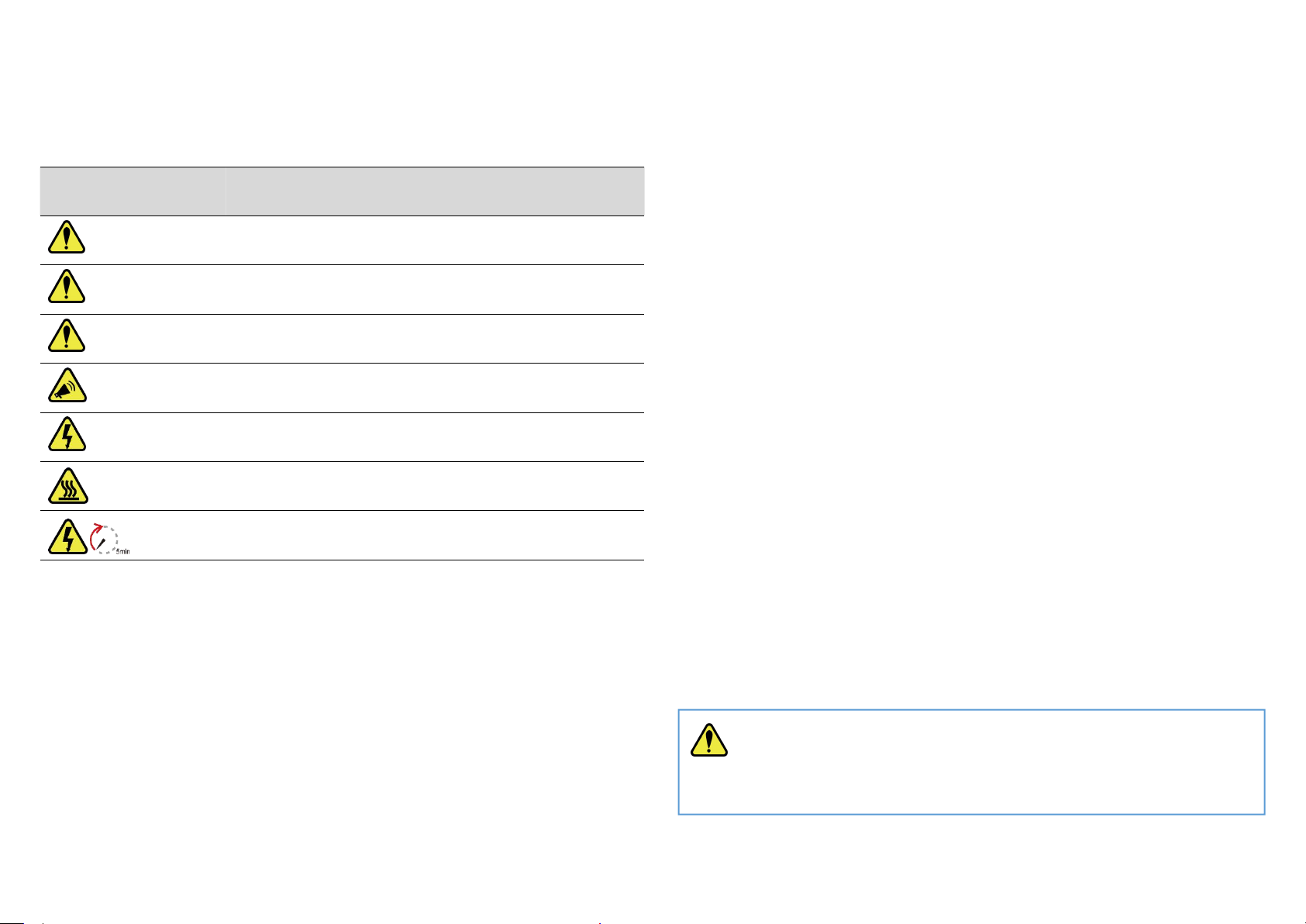
3.1 Safety Symbols
Symbol
Explanation
Indicates a high level of risk which, if not avoid, may
result in death or serious injur
DANGER y
Indicates a medium level of risk which, if not avoid,
may result in death or serious injur
WARNING y
Indicates a low level of risk which, if not avoid, may
result in minor or moderate injur
CAUTION y
Indicates a situation which, if not avoided, may
result in device damage or property damag
NOTE e
Indicates a danger of electric shock or high voltag
ELECTRIC SHOCK e
Indicates hot surface, do not touc
HOT SURFACE h
Notice of waiting at least 5 minutes before operatio
WAIT
n
The inverters involved in this manual comply with applicable safety and
technical regulations in design and test. To avoid personal injury and propert
3.2 Safety Instructions and Notice for Use
y
damage and to ensure longer service life of the machines, please read this
manual carefully and observe all safety information during operation.
Improper operation may result in risk of person injury or damage to the
machine and to other property, so please ensure that the following
requirements are met before or during operation.
Installation of inverters must be performed by qualified technicians, and
be in compliance with applicable electrical standards, regulations and the
requirements of local power authorities.
Wear protective equipment for all work on the machines: helmet,
insulated footwear, gloves, etc.
Ensure that unauthorized persons and children have no access to the
machines.
Do not open the housing of the machines at any time. Unauthorized
opening will void guarantee and warranty and may damage the
machines.
Do not touch non-insulated parts or cables, disconnect the machines
from voltage sources and guarantee no possible re-connection before
working on the machine.
Use measuring devices with a DC input voltage range of 600 V or higher
only.
High voltage is present in the live parts and cables inside the product
during operation, wait at least 5 minutes after disconnecting voltage
sources.
operation. To avoid being burnt, do not touch the inverter during
operation.
Pack inverters properly during transportation, and do not transport the
The temperature of some parts of the inverter may exceed 60 ℃during
m
together with flammable material.
4. Mounting
4.1 Installation Location
The following points should be considered when selecting an installation
WARNING
Do not select locations storing flammable material which may cause fire
or ex
p
losion!

9 10
location.
The wall bearing inverters shall be able to hold the weight of at least 4
times of the weight of the inverters.
The location shall be convenient for electrical connection, operation and
maintenance.
The ingress protection of the inverter is IP66, so it can be installed both
indoors and outdoors.
The temperature of the cooling fin may exceed 75 ℃, so select safe
locations.
The location must be well ventilated and sheltered from direct sunlight,
rain or snow.
Ensure the visibility of the LED lights and LCD display on the front panel
of inverters.
Install inverters vertically or with a backward tilt within 15 degrees. No
lateral tilt is allowed.
If more than one inverter are installed in one location, a minimum 150
mm clearance should be kept between two inverters and a minimum 300
mm clearance between inverters and the ground.
The Inverter is to be installed in a high traffic area where the fault is likely
to be seen.
4.2 Inverter Mounting
Appearance of the mounting bracket:
Procedures:
1) Ensure that the bracket is horizontal. Mark the position of the drill holes.
For brick walls, the position of the holes should suit expansion screws.
2) Use a 10 mm drill bit to drill mounting holes of 40 mm deep.
3) Insert the expansion tubes into holes.
4) Screw the expansion screws into expansion tubes with a cross
screwdriver to fix the bracket on the wall.
5) Lock the inverter to the mounting bracket with screws.
5. Electrical Connection
5.1 DC Side Connection of Inverters
PV strings should be connected to the inverter through special PV connectors
that are in the scope of delivery.
NOTE: To protect your hands from scratch, please wear gloves!
DANGER ELECTRICAL SHOCK
Lethal high voltage will be generated by PV arrays under sunlight, so
please disconnect DC and AC breakers and ensure no possibility of
re-connection before conduct electrical connection!

11 12
It is recommended to use the DC cable of 4 mm2or 6 mm2.
Assemble DC cables to DC connectors:
1) Strip the insulation layer off the DC Cable for a little length.
2) Insert the wire into the Crimp Contact and crimp them with an electrical
crimp-er.
3) Thread the cable through the Cable Gland, insert it into the insulator, and
gently pull backward the cable to ensure firm connection. Then screw up
the Cable Gland to the Insulator.
Install the DC connectors to the Inverter:
1) Turn the Grid Supply Main Switch OFF.
2) Turn the DC switch OFF.
3) Connect the DC connectors to the Inverter, small click confirms
connection. Please guarantee the correct polarity of the connection.
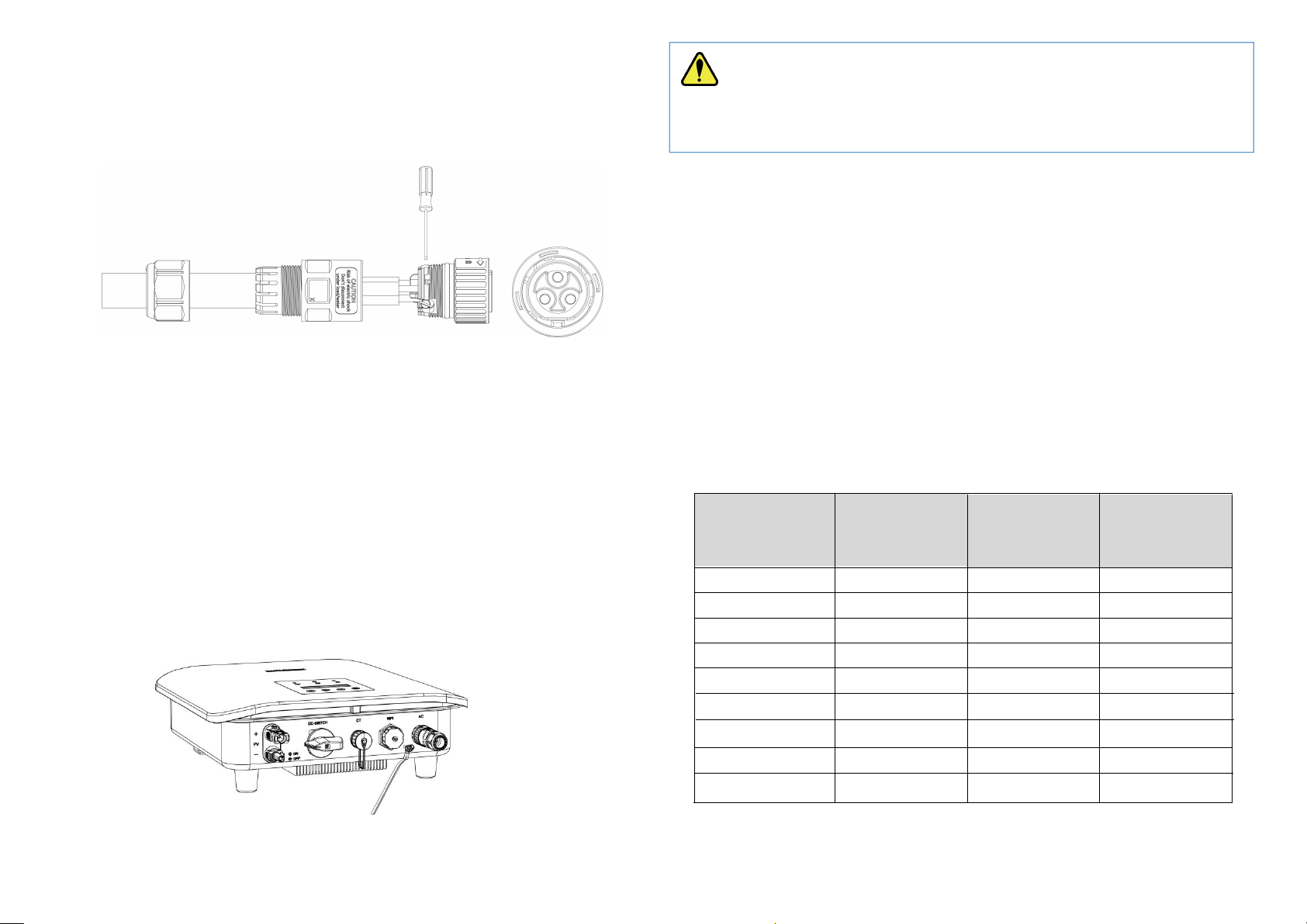
5.2 AC Side Connection of Inverters
When connecting an inverter to the utility grid, please use 4 mm² outdoor
cable.
An AC Connector is supplied together with the inverter.
AC Connector
Procedures:
1) Strip the insulation layer off the AC cable about 7 to 10 mm.
2) Thread the AC cable through the Nut and the Housing.
WARNING
Ensure that the open circuit voltage of PV array is within the max. input
voltage of the inverter!
NOTE: Use DC cables specialized for photovoltaic systems Only!
WARNING:Do not turn off DC switch directly for accident reverse
connection of DC inputs or any fault of inverters as it may damage
inverters. In that case, turn off the DC switch only when the DC current is
below 0.5 A.
NOTE: Use only the supplied connector or the connector with IP 65
or above to guarantee that the protection ingress of the whole inverter is
IP66!
13
3) Connect wires to the Terminal Block
14
:
insert yellow green wire to the grounding (PE) terminal, red or brown
to live line (L) terminal and blue or black to zero line (N) terminal;
screw up screws on the connectors with a straight screwdriver and
pull back wires to ensure firm connection.
4) Connect the Nut, Housing and Terminal Block together, a small click
confirms secure connection.
5) Connect the AC connector to the inverter, a small click confirms
connection.
5.3 External Grounding Connection
The external grounding port is located beside the AC connection terminal of
the inverter.
Procedures:
Prepare an OT terminal M4, crimp a grounding cable to the terminal, insert a
fastening screw into the OT terminal, insert them to the grounding port on
the inverter, and screw them tightly.
5.4 Earth Fault Alarm
The inverters are designed with an earth fault alarm function. If an earth fault
occurs, the inverters will stop generating power, the red alarm light will be on
and the LCD will display ‘ISO Out Range’ or ‘PEN No Connect’. In that case,
please refers to Chapter 7 for troubleshooting or contact Zhejiang Chisage for
help.
5.5 Over Current Protection Device
It is recommended to install a breaker (over current protection device (OCPD))
to protect the AC grid connection conductors. The table below is the
recommended parameter of an OCPD ratings for the Inverter.
Inverter Rated output
voltage (V)
Rated output
current (A)
forCurrent
protection
device (A)
CE-1P2KEG 230 8.7 25
CE-1P3KEG-Mini 230 13.0 25
CE-1P3.6KEG 230 15.7 25
CE-1P4KEG-Mini 230 17.4 25
WARNING: The external grounding connection cannot replace
the connection of PE terminal in AC connection. Ensure that both the
external grounding connection and the PE connection are done properly!
CE-1P0.6KEG
CE-1P0.7KEG
CE-1P0.8KEG
CE-1P1KEG
CE-1P1.5KEG
230
230
230
230
230
2.6
3.0
3.5
4.3
6.5
25
25
25
25
25
15
16
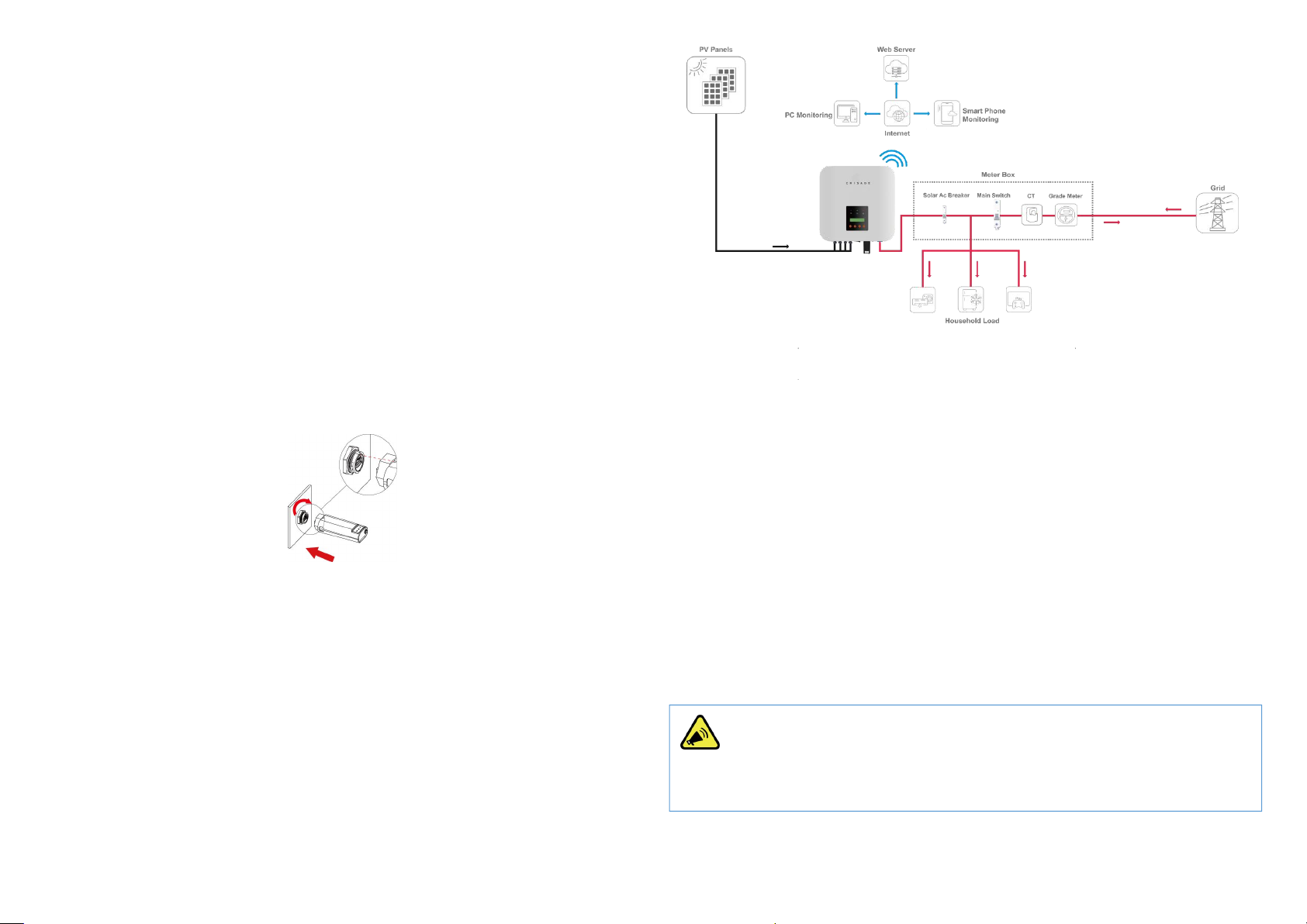
5.6 Communications Connection
The inverters have remote communications functions with the help of Wifi
sticks. The performance of inverters can be monitored remotely through a
specified APP or website.For the detail about the remote monitoring, please
refer to the specified manual.
WiFi/GPRS Stick Installation
Assemble WiFi/GPRS stick to the corresponding port on inverter as shown in
the diagram.
1) Plug the stick to the Wifi port on the inverter
2) Rotate the front operative part of the stick clockwise till the secure
connection of the stick
More detailed information about communications can be found in
corresponding manuals.
5.7 Electrical Connection Overview
The following is a diagram of a typical solar system for your reference to
install inverters.
5.8 Meter and CT Installation (optional)
A meter and CT(current transformer) can be connect to corresponding ports
on inverter to monitor electricity parameter such as current, voltage, power,
etc. and to realize export power management.
The suggested parameter:
Max input current for meter: 120A
Max measuring current for CT: 100A
Detail specifications of meter and CT can be found on Zhejiang Chisage
Website and a customer can purchase a suitable meter and CT for inverters
on the website.
NOTE
No need to change any parameter of the meter as it has been preset in the
factory!

17 18
Meter and CT connection:
For more information about meter and CT connection, please refer to
corresponding manuals on Zhejiang Chisage website.
The following is schematic diagrams for reference.
CT Installation Electrical Diagrams
Single Phase Meter Installation Electrical Diagrams
5.10 DRM (Demand Response Mode)
The DRM port is only applicable to installations in Australia and New Zealand
as requires by the standard of AS/NZS 4777.2:2020. The inverter detects and
initiates a response to the demand response modes listed in the followin
5.9 Residual Current Device (RCD)
An internal residual current device is integrated in the inverter to protect
against any potential residual current. If the residual current that exceeds a
set limit is detected, the inverter will stop working, the warning light will be
on and the LCD will display ‘GFCI Device Fault’ or ‘GFCI Out Range’.
If you need to install an external RCD as required by local grid company, we
suggest a Type-A RCD with a threshold current higher than 100 mA.
g
table.
Mode
Functions
DRM 0 Operate the disconnection device
DRM 5 Do not generate power
DRM 6 Do not generate at more than 50 % of rated power
DRM 7 Do not generate at more than 75 % of rated power AND absorb reactive
power if capable
DRM 8 Increase power generation (subject to constraints from other active
DRMs)
Ways to connect a DRED (demand response enabling device) to inverters
1) Assemble a RJ45 connector by connecting a network cable to the RJ45
according to the international conventional method;
2) Plug the RJ45 connector to the DRM port of the inverter.
Power rate limit modes as required by AS/NZS 4777.2:2020 is supported in
this inverters. When a demand response mode (except for DRM 0) is asserted
or unasserted the power rate limit will apply to the increase or decrease in
power generation or consumption and the transitions between power levels.
When a DRED is connected to an inverter, the inverter will receive and
response to the outside signal directly. And the DRM working mode will be
shown in the BASIC INFO in the LCD menu.
DANGER ELECTRICAL SHOCK
Turn off upstream and downstream electrical connection before the
meter installation!

19 20
6. Operation
6.1 Start and Stop Inverters
6.1.1 Inverter Turning-on
The following procedures have to be followed exactly to start an inverter.
1) Turn on the AC breaker.
2) Turn on the DC Switch.
3) After a compulsory delay of 30 to 300 seconds, the inverter will start to
work and the POWER light will be on.
6.1.2 Inverter Turning-off
The following procedures have to be followed exactly when stop an inverter.
1) Switch off the AC Switch.
2) Wait around 30 seconds for the capacitor to dissipate energy. Then turn
the DC switch OFF.
3) Be sure that all LED light is OFF (around 1 minute).
6.2 LCD Operation
6.2.1 Main Menu
When the inverter has been started, the LCD screen shows operation status
and power of the inverter alternately every 10 seconds (refer to below figure).
You can press UP and DOWN keys to scroll the screens and press ENTER key
to access the main menu. The main menu includes four sub-menus: BASIC
INFO, BASIC SETUP, DETAIL INFO, and TECHNICAL SET.
6.2.2 Basic Info.
The table below explains the meaning of information displayed in the
sub-menu of Basic Info.
CAUTION WAIT
Beware of the risk of electrical shock! Wait at least 5 minutes before
touching the machine although the DC switch has been turn off!
WARNING
Ensure that the open circuit voltage of PV array is within the max. input
voltage of the inverter!
DANGER ELECTRIC SHOCK
High voltage may present, please beware of the risk of electric shock and
take protection precautions!

21 22
No.
Displays Duration Explanation
1 10 S Total energy: total energy generated
2 10 S
This Month: total energy generated
this month
Last Month: total energy generated
last month
3 10 S
This Day: total energy generated today
Previous Day: total energy generated
yesterday
4 10 S
DC voltage1: the DC voltage of the PV
input 1
DC current1: the DC current of the PV
input 1
6 10 S
AC voltage: the voltage of the utility
grid
AC current: the current of the utility
grid
7 10 S
Frequency: the frequency of the utility
grid
Output Power: 1000 W
8 10 S Cumulative energy generation time
9 10 S Inverter SN: The SN of the Inverter
EE00S005000001A1
10
Working Mode:
DRM(Demand respons10 S e mode)
Number:
11
10 S
This menu indicates the current
country grid code or safety standards
selected
Customers are able to view those info without password including country
grid code. cAUSAS4777_2A, cAUSAS4777_2B, cAUSAS4777_2C and
cNZS4777_2 represent Australia A, Australia B, Australia C and New Zealand
standard respectively.
6.2.3 BASIC SETUP
You can set time and address in this sub-menu.
No. Display Explanation
1 To set up time
2 To set up RS485 address
3 To set up language
6.2.3.1 Time Setting-up
When the sub-menu of ‘SET TIME’ is selected, the LCD will display the screen
as below.
Press ENT to move the cursor from left to right, Press UP/DOWN to select a
number for a selected digit. Press ESC to save the setting and return to the
main menu.
6.2.3.2 Address Setting-up
The inverter RS 485 address communicating with a monitoring platform can
DC VOL1: 401.5V
DC CUR1: 18.6A
AC VOL: 230.6V
AC CUR: 38.8A
TOTAL RUNTIME:
152 H
TOTAL ENERGY
50000 Kwh
ThisMon: 255Kwh
LastMon: 254Kwh
TODAY: 52 Kwh
PRE_DAY : 54Kwh
INVERTER SN
EE00S005000001A1
SET TIME
SET RS485 ADDR
NEXT = ENT OK = ESC
25-01-2022 18:23
GRID FREQ:50.2Hz
POWER : 1000 W
SET LANGUAGE
MODLE:
Volt-Watt
Standard
cAusas4777_2A
23 24
be set here, the address ranges from ‘01’ to ‘99’, and the default address is
‘01’.
Press UP/DOWN to scroll through numbers for a selected digit, press ENT to
save the setting and return to the main menu, and press ESC to return to the
main menu without saving the setting.
6.2.3.3 Language Setting-up
Working language of the inverter can be set here, and the default language is
English.
6.2.4 Detail Info - Maintenance Personnel Only
Select ‘Detail Info’ from the main menu and the LCD screen will display the
following information:
Steps to view the menu of the Detail Info.:
1) Enter the password:
Please contact your inverter supplier for the default password. When finishing
password entering, press ENT to verify the password. If the password is
correct, the sub-menu will be displayed, and if wrong, the LCD will display
‘Wrong Password’ and return to the previous menu. Press ESC to return to
the main menu.
2) Access the sub-menu:
After enter the correct password, the sub-menus will be displayed:
1. Operation Info, 2. Fault Info, 3. Warning Info, 4. SW Version, 5. Rated
Power, 6. Rated Voltage, 7. Daily Energy, 8. Monthly Energy, 9. Yearly Energy,
10. Export Total, 11. Export Today
Press UP/DOWN to scroll the screen, press ENT to go into the selected
sub-menu and press ESC to return to the main menu.
6.2.4.1 Operation Information
This information is for maintenance personnel to get the operation
information, and the information is as below:
No.
Display Duration Explanation
110 S This menu indicates:
GFCI RMS: Leakage current
protection
ISO: Ground fault
protection/Insulation Resistance
210 S This menu indicates:
The temperature of heat sink of
inverters
310 S This menu indicates:
Inverter inner temperature
410 S This menu indicates:
Bus voltage
AC direct component
510 S This menu indicates:
Power factor ratio
Output power limit
610 S This menu indicates:
Residual current protection
Insulation Resistance/Ground
fault protection
YES = ENT EXIT = ESC
Slave Add: 01
NEXT = ENT EXIT = ESC
Password: 0000
GFCI RMS: 10 mA
ISO : 1.25 kΩ
Heatsink Temp
65.5 ℃
Inv Inner Temp
45.0 ℃
BusVol: 385.5V
DCI : 0 mA
PF:+1.00 ac
Pac Limit: 80%
RCD(GFCI): ON
PVISOGuard: ON
25 26
7
10 S This menu indicates:
All PV in parallel mode
MPPT shadow mode
810 S This menu indicates:
Self examination of AC relay
Output direct component
protection
910 S This menu indicates the apparent
power
10 10 S This menu indicates the active
power
11 10 S This menu indicates the reactive
power
12 10 S This menu indicates the power
exported to grid
The operation info of inverter and part of protection info. can be view after
password has been input and all the info. is included in the above table. Press
UP/DOWN to scroll the screen to view.
6.2.4.2 Fault Info.
When a fault happens, the Alarm Light will be on, and the LCD will display a
brief description of the fault. Please refer to Chapter 7 for troubleshooting or
contact after-sales department if a fault info. is displayed.
6.2.4.3 Warning Info.
If a adverse condition presents in the inverter, the LCD will display a warning
information. The inverter will work normally with such warning conditions.
When a warning info. is displayed, please refer to Chapter 7 for
troubleshooting.
6.2.4.4 Software Version/Firmware Version
The software version or firmware version of the inverter is displayed and is
accessible for technicians only.
6.2.4.5 Rated Power
The rated power of the inverter is displayed here.
6.2.4.6 Rated Voltage
The rated voltage of the inverter is displayed here.
6.2.4.7 Daily Energy
The energy generated for a specified day can be checked here.
NOTE: This operation is for maintenance personnel only. Password
is required to access this part! Please reset the password at the first
operation.
ACHCT Device
Fault
Warning Info
0x00000400
Rated Power
5KW
Select Day
2020-02-22
SW Version
V01.05
AllPVParal: ON
MPPTShadow:
RelayCheck:OFF
DCI Prot : ON
Apparent Power
2000 VA
Active Power
2000 W
Reactive Power
2000 Var
Export Power
4800W
Rated Voltage
220V

27 28
6.2.4.8 Monthly Energy
The energy generated for a specified month can be checked here.
6.2.4.9 Yearly Energy
The energy generated for a specified year can be checked here.
6.2.4.10 Export Total
Total energy exported to grid can be checked here.
6.2.4.11 Export Today
The energy exported to grid today can be checked here.
6.2.5 Technical Set – Maintenance Personnel Only
This section is for maintenance personnel only, enter password to access the
sub-menu as guided by Chapter 6.2.4.
The sub-menu:
No.
Display Explanation
1 To enable the setting-up of all
functions under the menu of
Technical Set
2
To set up safety standard or
country grid code for the inverters
3 To set up the high limit of AC
output voltage
4 To set up the low limit of AC
output voltage
5 To set up the high limit of AC
output frequency
6 To set up the low limit of AC
output frequency
7 To set up the max generation
power
8 To set up the AC instant voltage
limit
9 To set up the power control
10 To set up the increase power rate
limit and decrease power rate limit
11 To set up special functions
Pmax Limit
VAC L Limit
VAC H Limit
Standard Set
ALL Set Enable
Select Month
2020-02-22
YearSelect
2020-02-22
FAC H Limit
FAC L Limit
Special Func
Standard Func
Power Control
AC Inst Limit
Total
Export
500KWh
Today
Export
500KWh

29 30
12 To set up passwords
13 To restore factory settings
14 To adjust the total power
generated
15 To clear the power generation
record
16 To turn on or turn off inverters
17 To set up export power limit
Press UP/DOWN to scroll the menu, press ENT to access the sub-menu, and
press ESC to return to the previous menu.
6.2.5.1 All Set Enable
This function is to enable all the setting-up functions under the menu of
‘Technical Set’. Before enabling or setting up any of the function under this
menu, please turn the ‘All Set Enable’ on.
6.2.5.2 Standards Set
The safety standard for different countries can be selected in this sub-menu.
Australia A, Australia B, Australia C and New Zealand grid codes can be
selected here. cAUSAS4777_2A, cAUSAS4777_2B, cAUSAS4777_2C and
cNZS4777_2 represent Australia A, Australia B, Australia C and New Zealand
standard respectively.
Procedures:
Step1: go to ‘All Set Enable’ in the menu of ‘TECHNICAL SET’ and turn the
status to ‘ON’.
Step2: move to ‘Standard Set’ and get inside
Step3: select the country grid code needed.
Press UP/DOWN to scroll through the national standards, press ENT to
confirm the safety standard, and press ESC to return to the previous menu.
6.2.5.3 AC Output Voltage Limit
This section is to set up the high and low limit of AC output voltage as
permitted by local grid company if the grid voltage is beyond the range
specified by national standards.
The detailed procedure is described in a separated document named ‘Voltage
Adjustment’.
6.2.5.4 AC Output Frequency Limit
This section is to set up the high and low limit of AC output frequency as
permitted by local grid company if the grid frequency is beyond the range
specified by national standards.
Standard Set
cAusas4777_2A
VAC H Limit Set
270V
VAC L Limit Set
180V
Export Limit
ALL SET Enable
ON
Factory Reset
Set Passwords
Adjust Total E
Reset Total E
Inverter ON/OFF
NOTE: This part is accessible for qualified and accredited
technicians only!
NOTE: This operation is for maintenance personnel only. Password
is required to access this part!
31 32
The method to set up the AC output frequency limit is similar to that of AC
voltage adjustment.
6.2.5.5 Max Generation Power Setup
The max output power can be set up here.
The detailed procedure to set up the Max generation power is described in a
separated document named ‘Power Generation Limit’.
6.2.5.6 Power Control
No.
LCD Display Explanation
1 To set up reactive power
2 To set up power factor
3 To restore reactive power
4 To restore power factor
Reactive power and power factor can be set up and restored here.
The power quality response modes as required by the standard of AS/NZS
4777.2:2020 can be activated or controlled under this menu combined with
the menu of special function. The detail procedure will be described in the
following part.
6.2.5.7 Standard Function
Power increase slope and decrease slope can be set up here.
This part is for the setup of power rate limit modes as required by AS/NZS
4777.2:2020. Soft ramp up after connect, reconnect or soft ramp up/down
following a response to frequency disturbance is available in those inverters.
Procedures to set up the gradient of power rate limit:
Step1: Go to ‘All Set Enable’ in the menu of ‘TECHNICAL SET’ and turn the
status to ‘ON’.
Step2: Go to ‘Standard Func’ and then get inside.
Step3: Go to set up the ‘Pwr UpSlope’ or ‘Pwr DownSlope’ for the soft ramp up/down
of rated power per minute.
.
6.2.5.8 Special Function Setup
No.
LCD Display Explanation
1To set up the constant PV voltage
Pmax Limit
70% of Prated
Q Set
+60%
YES=ENT EXIT=ESC
Are You Sure?
YES=ENT EXIT=ESC
Are You Sure ?
PF Set
+80%
Q Reset
PR Reset
Set CV MPPT
FAC H Limit Set
52Hz
FAC L Limit Set
47Hz
Pwr UpSlope
90%
Pwr DownSlope
20%
NOTE: This operation is for maintenance personnel only. Password
is required to access this part!

33
34
2
To set up the multiple MPPTs parallel
mode
3
To enable the High Voltage Ride Through
4
To enable the Low Voltage Ride Through
5
To enable the bus mid-point voltage
protection
6
To enable the DC component inspection
7
To enable the GFCI protection
8
To enable the ISO protection
9
To enable the island protection
10
To enable the buzzer
11
To enable the relay
12
To enable the QU curve
13
To enable the PF curve
14
To enable the Q curve
15
To enable the PU curve
16
To enable the shadow MPPT mode
6.2.5.8.1 Island Protection
The active anti-islanding protection of the inverters is achieved by shifting the
frequency of the inverter away from nominal conditions in the absence of a
reference frequency (frequency shift). It is enabled by default.
6.2.5.8.2 Volt-var Response Mode
The QU Curve is enabled by default. The volt-var response mode changes the
reactive power absorbed or supplied by the inverter in response to the
voltage at its grid-interactive port. The diagram and table below are the
response mode required for the volt–var response according to the standard
of AS/NZS 4777.2:2020.
1/2BUS Prot
LVRT
Shadow MPPT:
PF CURVE
QU CURVE
ISO Prot
DCI Prot
GFCI Prot
All PV Paral
HVRT
Island Prot
Buzzer Enabled
Relay Check
Q CURVE
QU CURVE ON
PU CURVE

35 36
Region
Default Value VV1 VV2 VV3 VV4
Australia A Voltage 207 V 220 V 240 V 258 V
Inverter reactive
power level
(Q)% of Srated
44%
supplying
0% 0% 60%
absorbing
Australia B Voltage 205 V 220 V 235 V 255 V
Inverter reactive
power level
(Q)% of Srated
30%
supplying
0% 0% 40%
absorbing
Australia C Voltage 215 V 230 V 240 V 255 V
Inverter reactive
power level
(Q)% of Srated
44%
supplying
0% 0% 60%
absorbing
New
Zealand
Voltage 207 V 220 V 235 V 244 V
Inverter reactive
power level
(Q)% of Srated
60%
supplying
0% 0% 60%
absorbing
Procedures to enable or disable the Volt-var Response Mode:
Step1: go to ‘All Set Enable’ in the menu of ‘TECHNICAL SET’ and turn the
status to ‘ON’.
Step2: go to ‘Special Func’ and then go to ‘QU Curve’
Step3: enable or disable the ‘Volt-var Response Mode’ by changing the status
to ‘ON’ or ‘OFF’.
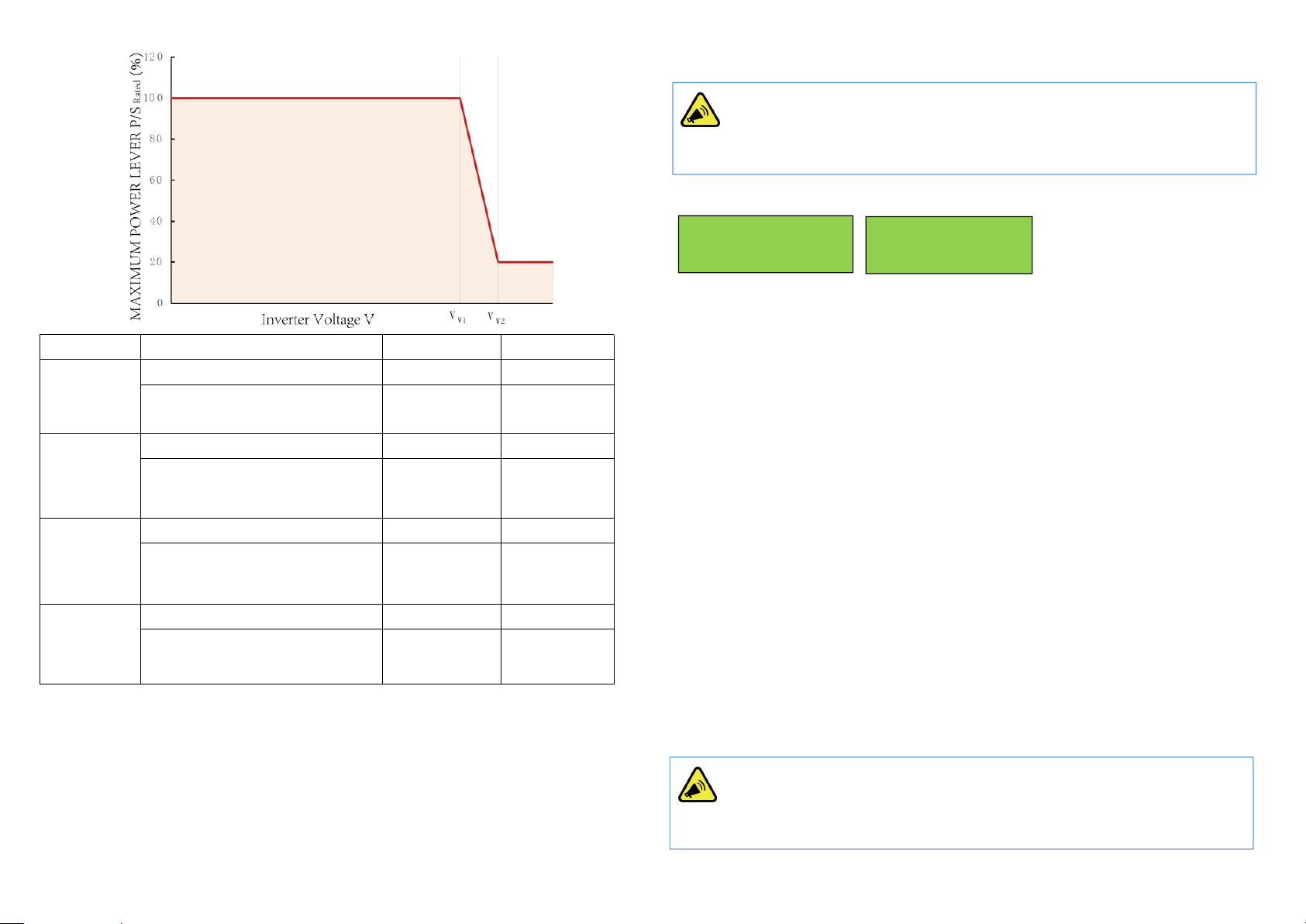
6.2.5.8.3 Volt-watt Response Mode
The PU Curve is enabled by default. The volt-watt response mode varies the
maximum active power output level of the inverter in response to the voltage
at its grid-interactive port. The diagram below is the response curve required
for the volt–watt response according to the standard of AS/NZS 4777.2:2020.
PU CURVE ON
NOTE: This operation is for maintenance personnel only. Password
is required to access this part!
37 38
Region
Default Value Vw1Vw2
Australia A Voltage 253 V 260 V
Inverter maximum active power
output level (P)% of Srated
100% 20%
Australia B Voltage 250 V 260 V
Inverter maximum active power
output level (P)% of Srated
100% 20%
Australia C Voltage 253 V 260 V
Inverter maximum active power
output level (P)% of Srated
100% 20%
New
Zealand
Voltage 242 V 250 V
Inverter maximum active power
output level (P)% of Srated
100% 20%
Procedures to enable or disable the Volt-watt Response Mode:
Step1: go to ‘All Set Enable’ in the menu of ‘TECHNICAL SET’ and turn the
status to ‘ON’.
Step2: go to ‘Special Func’ and then go to ‘PU Curve’
Step3: enable or disable the ‘Volt-watt Response Mode’ by changing the
status to ‘ON’ or ‘OFF’.
6.2.5.8.4 Fixed Power Factor Mode or the Reactive Power Mode
Those modes are disabled by default. The fixed power factor mode or the
reactive power mode may be enabled in some situations by the electrical
distributor to meet local grid requirements, one of these modes shall be
enabled if the volt-var mode is disabled.
Procedures to set up the Reactive Power Mode:
Step1: go to ‘All Set Enable’ in the menu of ‘TECHNICAL SET’ and turn the
status to ‘ON’.
Step2: go to ‘Special Func’, then go to ‘Q Curve’ and enable the Q Curve by
change the status to ‘ON’
Step3: go to ‘Power Control’ and then go to ‘Q Set’.
Step 4: Set up the Reactive Power Mode manually.
Procedures to set up the Fixed Power Factor Mode:
Step1: go to ‘All Set Enable’ in the menu of ‘TECHNICAL SET’ and turn the
status to ‘ON’.
Step2: go to ‘Special Func’, then go to ‘PF Curve’ and enable the PF Curve by
change the status to ‘ON’
Step3: go to ‘Power Control’ and then go to ‘PF Set’.
Step 4: Set up the Fixed Power Factor manually.
PF CURVE OFF Q CURVE OFF
NOTE: This operation is for maintenance personnel only. Password
is required to access this part!
NOTE: This operation is for maintenance personnel only. Password
is required to access this part!
This manual suits for next models
8
Table of contents
Other CHISAGE Inverter manuals


