TSN Systems Box 3.0 User manual

TSN Box 3.0 Getting Started Guide
TSN Box Development
Exported on 04/04/2019

TSN Box Development – TSN Box 3.0 Getting Started Guide
– 2
Table of Contents
1 Introduction ...............................................................................................4
2 Hardware....................................................................................................4
2.1 General Description .......................................................................................................4
2.2 Technical Description ....................................................................................................4
2.3 Mechanics.......................................................................................................................6
2.4 Components...................................................................................................................6
2.4.1 TAP Side Connectors..................................................................................................................................6
2.4.2 Host Side Connectors ................................................................................................................................7
2.4.3 USB 2.0........................................................................................................................................................8
2.4.4 USB 3.0.......................................................................................................................................................9
2.4.5 USB Serial Debug Port ..............................................................................................................................9
2.4.6 Host Ethernet .............................................................................................................................................9
2.4.7 Isolated GPIO............................................................................................................................................10
2.4.8 Audio Ports ...............................................................................................................................................11
2.4.9 Dual 1Gb Ethernet Module.......................................................................................................................12
2.4.9.1 1000BASE-T ..............................................................................................................................................12
2.4.9.2 1000BASE-T1 ............................................................................................................................................12
2.4.10 Quad 100 Mbps Module...........................................................................................................................13
2.4.10.1 100BASE-T1 .............................................................................................................................................13
2.4.10.2 100BASE-TX .............................................................................................................................................13
2.4.11 CAN Module ..............................................................................................................................................14
2.4.11.1 Pinout ......................................................................................................................................................14
2.4.11.2 Termination Switches .............................................................................................................................14
2.4.12 SYNC module............................................................................................................................................15
2.4.12.1 Sync Mode................................................................................................................................................15
2.4.12.2 PPS Mode.................................................................................................................................................15
2.4.13 PPS IO .......................................................................................................................................................16
2.4.14 Reset ........................................................................................................................................................16
2.4.15 Recovery Button......................................................................................................................................16
2.4.16 Power........................................................................................................................................................16
2.4.16.1 Terminal Block Header (Green)..............................................................................................................16
2.4.17 Earth/Chassis ...........................................................................................................................................17

TSN Box Development – TSN Box 3.0 Getting Started Guide
– 3
2.4.18 Thermal Considerations ..........................................................................................................................17
2.5 Software (Web based)..................................................................................................17
2.5.1 Prerequisites ............................................................................................................................................17
2.5.2 Getting started .........................................................................................................................................17
2.5.3 Network discovery ...................................................................................................................................17
2.5.4 Web Interface ...........................................................................................................................................18
2.5.4.1 Packet generator:.....................................................................................................................................19
2.5.4.2 Packet generator with burst (PTP master) .............................................................................................20
2.5.4.3 Packet generator with burst (PTP automotive master).........................................................................21
2.5.4.4 Packet generator with burst (PTP automotive slave)............................................................................21
2.5.4.5 Packet generator with burst (PTP Slave)................................................................................................22
2.5.4.6 TAP configuration ....................................................................................................................................23
2.5.4.7 PcapNG Player PG PTP (Master)..............................................................................................................23
2.5.4.8 PcapNG Player PG PTP (Automotive master).........................................................................................26
2.5.4.9 PcapNG Player PG PTP (Automotive slave) ............................................................................................26
2.5.4.10 PcapNG Player PG PTP (Slave) ................................................................................................................27
2.5.4.11 Listener MAC Mode...................................................................................................................................27
2.5.4.12 Ssfedit (Web Version) ...............................................................................................................................29
2.5.4.13 Device Statistics .......................................................................................................................................30
2.5.4.14 Configuration/Hardware .........................................................................................................................32
2.5.4.15 Configuration/Sync Control ....................................................................................................................35
2.5.4.16 External Switch Configuration (Q5050 support only) ............................................................................35
2.5.4.17 Settings/Update Firmware ......................................................................................................................35
2.5.4.18 Settings/Change Password .....................................................................................................................36
2.5.4.19 Settings/Manage Users............................................................................................................................36

TSN Box Development – TSN Box 3.0 Getting Started Guide
Introduction – 4
1 Introduction
This is the manual for the TSN Box Version 3.0, onward referred to as the unit. The document describes the
hardware and software of the TSN Box.
2 Hardware
2.1 General Description
The unitis a high-performance analysis tool for time sensitive networks providing the following features:
•Host Intel® Celeron-series System-on-Chip (SoC)
•Intel® CeleronTM N2930, DC, 1.83/2.16GHz, 2MB L2 Cache
•8 GB DDR3 Memory
•2x USB2.0 Ports
•1x USB3.0 Port
•1x 1Gb Ethernet Port
•1x USB Serial Terminal Port
•2x Isolated Input
•2x Isolated Outputs (open-collector)
•1x Output Power (non-isolated)
•12x Audio Ports (6 x stereo connectors)
•8x Outputs channels
•4x Input channels
•2x High-speed GPI (SMA, 50Ωload impedance)
•2x High-speed GPO (SMA, 50Ωsource impedance)
•Front Panel Reset
•Front Panel General Purpose Button
•2x Dual 1Gb Modules
•Configured as either 2 x 1000BASE-T or 2 x 1000BASE-T1 or none
•1x Quad 100Mb Module
•Configured as either 4 x 100BASE-T1 or 4 x 100BASE-TX or none
•1x SYNC Module
•Configured as 2x PPS/SYNC Ports (50Ω) or none
•1x CAN Module
•Configured as 1x CAN Channel or none
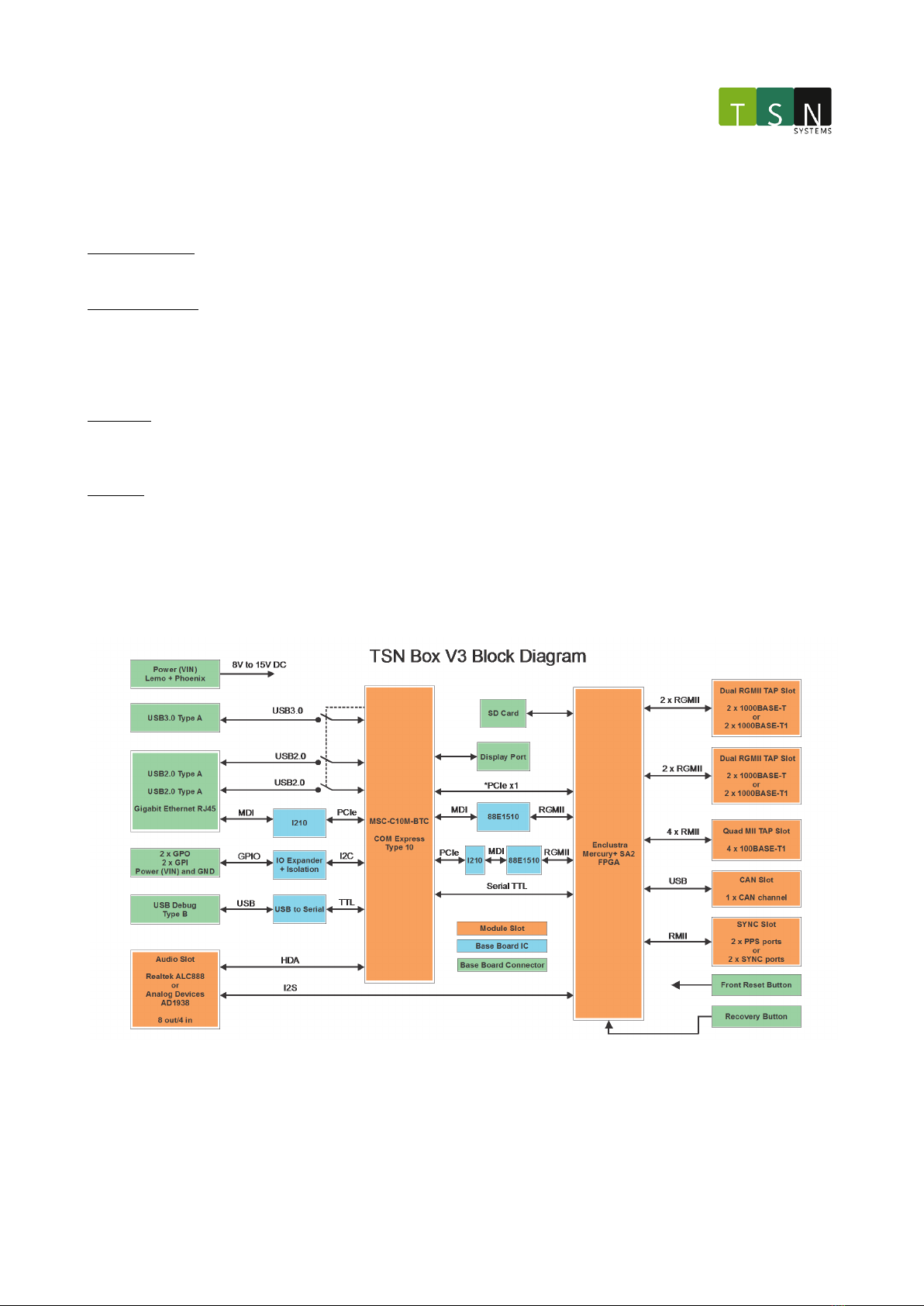
2.2 Technical Description
The unit consists of a base board with multiple module slots that can be configured in different options and
expanded on in future releases. There are 6 module slots in total.
Audio Slot
The Audio Module can be configured with 8 output channels and 4 input channels over 6 stereo 3.5mm connectors.
There are two audio codecs on the Audio Module, one controlled by the FPGA and one controlled by the Host CPU
as an HDA audio device. The input channels share the same connectors and the output channels are multiplexed
and controlled by the FPGA.
Dual 1Gb Slot #1
TSN Box Development – TSN Box 3.0 Getting Started Guide
Hardware – 5
The Dual 1Gb slot can be configured with a 1000BASE-T Module or a 1000BASE-T1 Module. The 1000BASE-T Module
consists of 2 x RJ45 connectors and is compatible with a standard CAT5 or CAT6 Ethernet cable. The 1000BASE-T1
Module consists of 2 x specialized Molex connectors and is compatible with the supplied single-UTP automotive
cables.
Dual 1Gb Slot #2
The second Dual 1Gb Slot functions the same as the first 1Gb Slot.
Quad 100Mb Slot
The Quad 100Mb Slot can be configured with a Quad 100BASE-T1 Module or a Quad 100BASE-TX module. The
100BASE-T1 Module consists of 4 x specialized Molex connectors and is compatible with the supplied single-UTP
automotive cables. The 1000BASE-TX Module consists of 4 x RJ45 connectors and is compatible with a standard
CAT5 or CAT6 Ethernet cable.
SYNC Slot
The SYNC slot can be configured with 2 x BNC connectors that functions as either 1 PPS Input Channel and 1 PPS
Output channel or 2 x SYNC channels (Rx and Tx). The mode is software controlled.
CAN Slot
The CAN slot can be configured with a CAN Bus Port that features a termination switch to switch in 120Ω
termination resistance at the connector.
The configuration of the unitis based on the user requirements.
The following block diagram shows an overview of the unitinternal layout:
*to be confirmed functional
TSN Box Development – TSN Box 3.0 Getting Started Guide
Hardware – 6
2.3 Mechanics
•Chassis dimensions: 210 mm x 150 mm x 74 mm
•Maximum envelope (with connectors): 210 mm x 187 mm x 74 mm
•Mass: ~4.5kg (Depends on modules loaded)
2.4 Components
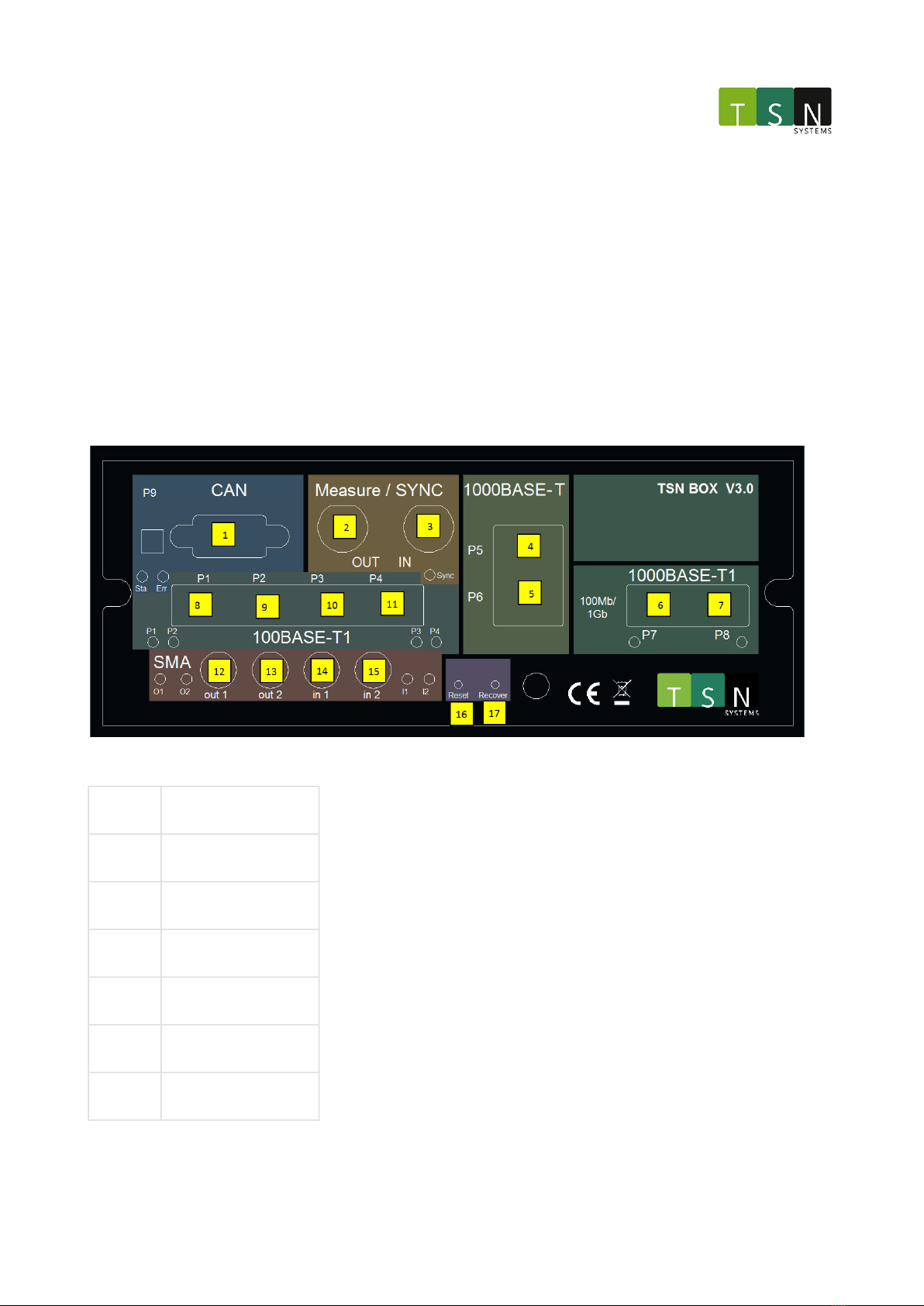
2.4.1 TAP Side Connectors
Number Description
1CAN – Port 9
2SYNC – Out
3SYNC – In
41000BASE-T – Port 5
51000BASE-T – Port 6
61000BASE-T1 – Port 7

TSN Box Development – TSN Box 3.0 Getting Started Guide
Hardware – 7
71000BASE-T1 – Port 8
8100BASE-T1 – Port 1
9100BASE-T1 – Port 2
10 100BASE-T1 – Port 3
11 100BASE-T1 – Port 4
12 SMA In 1
13 SMA In 2
14 SMA Out 1
15 SMA Out 2
16 Reset Button
17 Recovery Button
2.4.2 Host Side Connectors

TSN Box Development – TSN Box 3.0 Getting Started Guide
Hardware – 8
Number Description
1 DC in 8 - 15V
2 Host Ethernet
3 USB 2.0
4 USB 2.0
5 USB 3.0
6 USB Debug
7 Audio Out 1/2
8 Audio Out 3/4
9 Audio Out 5/6
10 Audio Out 7/8
11 Audio In 1/2
12 Audio In 3/4
13 GPIO In 1
14 GPIO In 2
15 GPIO Out 1
16 GPIO Out 2
17 GPIO power
2.4.3
USB 2.0
Two USB2.0 Type A connectors are available on the host side of the unitand are connected to the host PC. Pin
descriptions are shown below:

TSN Box Development – TSN Box 3.0 Getting Started Guide
Hardware – 9
2.4.4 USB 3.0
One USB3.0 Type A connector isavailable on the host side of the unitand is connected to the host PC. Pin
descriptions are shown below:
2.4.5 USB Serial Debug Port
The USB Serial Debug Port is connected to a FTDI USB to Serial converter chip. This serial channel is then
connected to the second serial port of the Host PC and is used for debugging purposes. A USB Type B cable is
required. FTDI VCP drivers may be required depending on OS.
2.4.6 Host Ethernet
The host Ethernet port is on the Host side. A standard RJ45 Ethernet cable is required; default IP address of the host
is 192.168.41.250.
TSN Box Development – TSN Box 3.0 Getting Started Guide
Hardware – 10
Pin Number12345678
Wire ColourWhite /
Orange
Orang
e
White /
Green
BlueWhite /
Blue
GreenWhite /
Brown
Brown
DescriptionBI_DA+BI_DA-
BI_DB+BI_D
C+
BI_DC-BI_D
B-
BI_DD+BI_DD
-
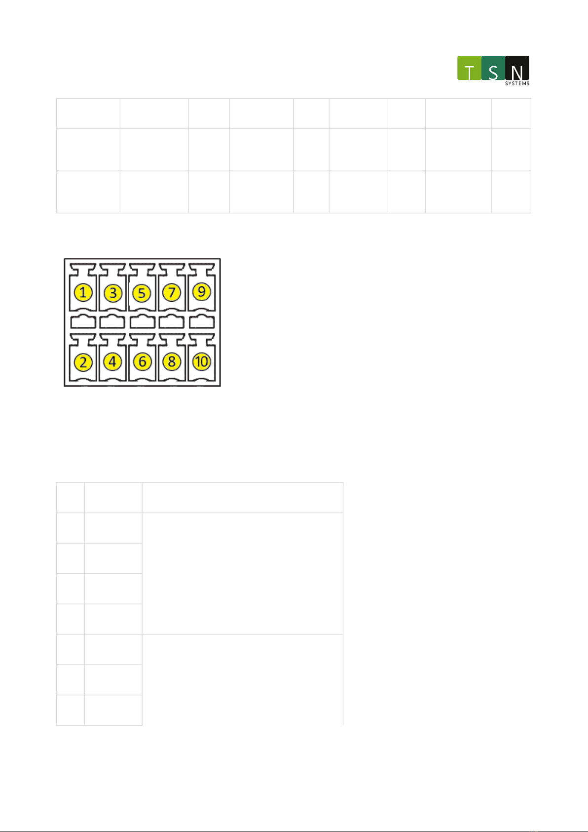
2.4.7 Isolated GPIO
There are 2 x electrically isolated inputs and 2 x isolated outputs, controlled by the host PC, as well as 12V nominal
power that may be used for powering attached GPIO devices. Note that the Ground and VIN are not isolated.
The mating connectoris the Phoenix Contact1952296, with two of these required. Pinouts and descriptions are
shown below.
PinRoleDescription
① Input 1-Logic 0: Vin> 2.5V
Logic 1: Vin< 1V
Maximum Voltage: 50V
Maximum current: 50mA
Rise time: 3us
Fall time 3us
② Input 1+
③ Input 2-
④ Input 2+
⑤ Output 1-Open-collector output
Maximum hold current: 500mA
Overcurrent protection: 1A
Maximum Voltage: 13V
⑥ Output 1+
⑦ Output 2-

TSN Box Development – TSN Box 3.0 Getting Started Guide
Hardware – 11
⑧ Output 2+
⑨GroundDirect ground connection
⑩VINDirectly connected to Power In (typically 12V)
Maximum hold current: 500mA
Overcurrent protection: 1A
2.4.8 Audio Ports
The Audio Moduleconsists of 8 x output channels and 4 x input channels. There are two audio codecs present on
the module, one is controlled by the FPGA and the other by the Host PC. The Host PC uses a Realtek ALC888 Codec
(CPU Mode) and the FPGA uses an Analog DevicesAD1938(FPGA Mode). The channels are multiplexed and is
software controlled.
• Input Impedance= 47kΩ (CPU mode) or11.4kΩ(FPGA mode)
•Maximuminput voltage = 6.0Vpp
• Maximumoutputvoltage =3.3Vpp
Belowarethe pindescriptionsof each 3.5mm stereo connector:
CPUmode FPGAmode
Audio PortTipRingSheathTipRingSheath
1 / 2Front-LFront-RGNDOut 2Out 1GND
3 / 4Surr.-LSurr.-RGNDOut 4Out 3GND
5 / 6CentreLFEGNDOut 6Out 5GND
7 / 8Side-LSide-RGNDOut 8Out 7GND
TSN Box Development – TSN Box 3.0 Getting Started Guide
Hardware – 12
9 / 10Line2-LLine2-RGNDIn 2In 1GND
11 / 12Line1-LLine1-RGNDIn 4In 3GND
2.4.9 Dual 1Gb Ethernet Module
The Dual 1Gb Ethernet modules can be configured as either 2 x 1000BASE-T ports or 2 x 1000BASE-T1 ports.
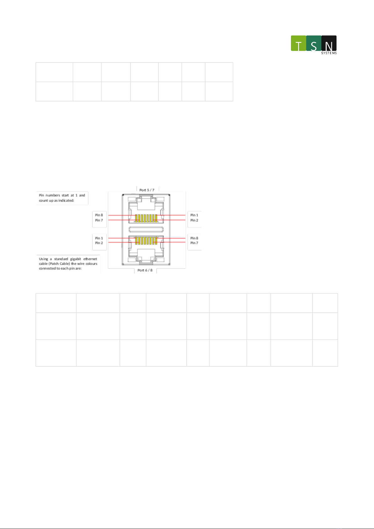
2.4.9.1 1000BASE-T
The Dual 1000BASE-T Tap Module uses a stacked RJ45 connector. For module slot 1 the top port is Port 5 and the
bottom is Port 6. For module slot 2 the top port is Port 7 and the bottom is Port 8. Below is a description of the
pinout.
Pin Number12345678
Wire ColourWhite /
Orange
Orang
e
White /
Green
BlueWhite /
Blue
GreenWhite /
Brown
Brown
DescriptionBI_DA+BI_DA-
BI_DB+BI_D
C+
BI_DC-BI_D
B-
BI_DD+BI_DD
-
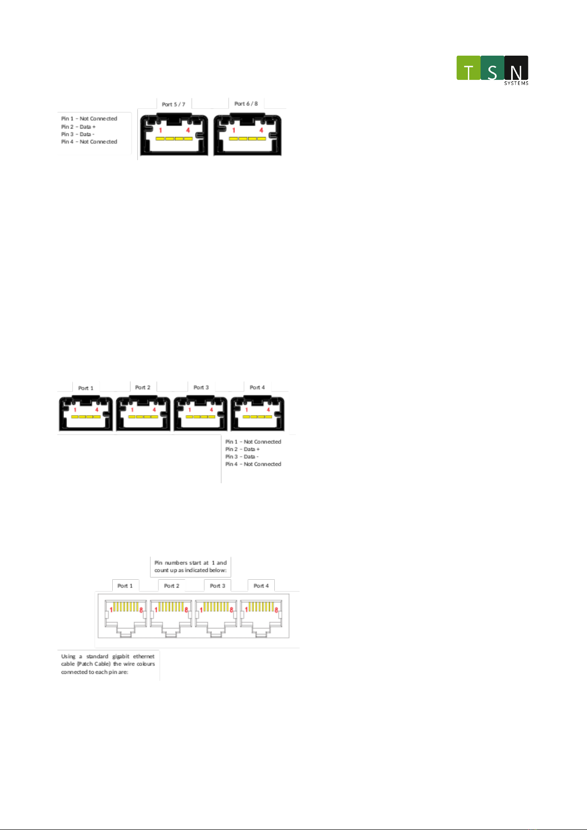
2.4.9.2 1000BASE-T1
The Dual 1000BASE-T1Tap Module uses two specialized Molex connectors. For module slot 1 the left port is Port 5
and the right is Port 6. For module slot 2 the left port is Port 7 and the right is Port 8. These connectors require a
specialized cable that is supplied with the unit. Below is a description of the pinout.
The mating connector is the Molex0347910040and uses two Molex5600230421contacts.
TSN Box Development – TSN Box 3.0 Getting Started Guide
Hardware – 13
2.4.10 Quad 100 Mbps Module
The Quad 100Mbps Module Slot can be configured with either a Quad 100BASE-T1 Module or a Quad 100BASE-TX
Module.
2.4.10.1 100BASE-T1
The Quad 100BASE-T1Tap Module uses four specialized Molex connectors. The ports are numbered 1 to 4 from left
to right. These connectors require a specialized cable that is supplied with the unit. Description of the pinout is
below.
The mating connector is the Molex0347910040and uses two Molex5600230421contacts.
2.4.10.2 100BASE-TX
The Quad 100BASE-TXTap Module uses fourstandard RJ45connectors. The ports are numbered 1 to 4 from left to
right. These connectorsare compatible with a standard RJ45 Ethernet cable. Below is a description of the pinout.

TSN Box Development – TSN Box 3.0 Getting Started Guide
Hardware – 14
Pin Number12345678
Wire ColourWhite /
Orange
Orang
e
White /
Green
BlueWhite /
Blue
Gree
n
White /
Brown
Brown
DescriptionTX +TX -RX +NCNCRX -NCNC
2.4.11
CAN Module
The CAN Module consists of aCAN bus interface over a DE-9 connector. A 'straight' DE-9 cable is supplied with the
unit. Note that the 12V supplied on pin 9 of the connector is a build option and does not come standard.
The mating connector is a standard DE-9maleconnector.
2.4.11.1 Pinout
Pin Number122456789
DescriptionNCCAN-LGNDNCShieldGNDCAN-HNC12V (Optional)
2.4.11.2 Termination Switches
When both switches are in theONposition, a 120Ωtermination resistance is addedbetween the CAN-H and CAN-L
bus signals. Both switches should be in the same position at all times for correct operation.

TSN Box Development – TSN Box 3.0 Getting Started Guide
Hardware – 15
2.4.12 SYNC module
The SYNC moduleconsists of twoBNC connectors that function as either 1 PPS Input Channel and 1 PPS Output
channel or 2 x SYNC channels (Rx and Tx). The mode is software controlled.
2.4.12.1 Sync Mode
Pin:Output SocketInput Socket
CentreTX +RX +
SheathTX -RX -
2.4.12.2 PPS Mode
Pin:Output SocketInput Socket
CentreOutIn
SheathGNDGND
The PPS IOhave the following electrical specifications:
Input:
• Logic high requires>= 2.0V
• Logic low requires<= 0.8V
•Load termination impedance = 50Ω
Output:
• Output Voltage= 5V
• Maximum output current=60mA
•Source impedance = 50Ω
TSN Box Development – TSN Box 3.0 Getting Started Guide
Hardware – 16
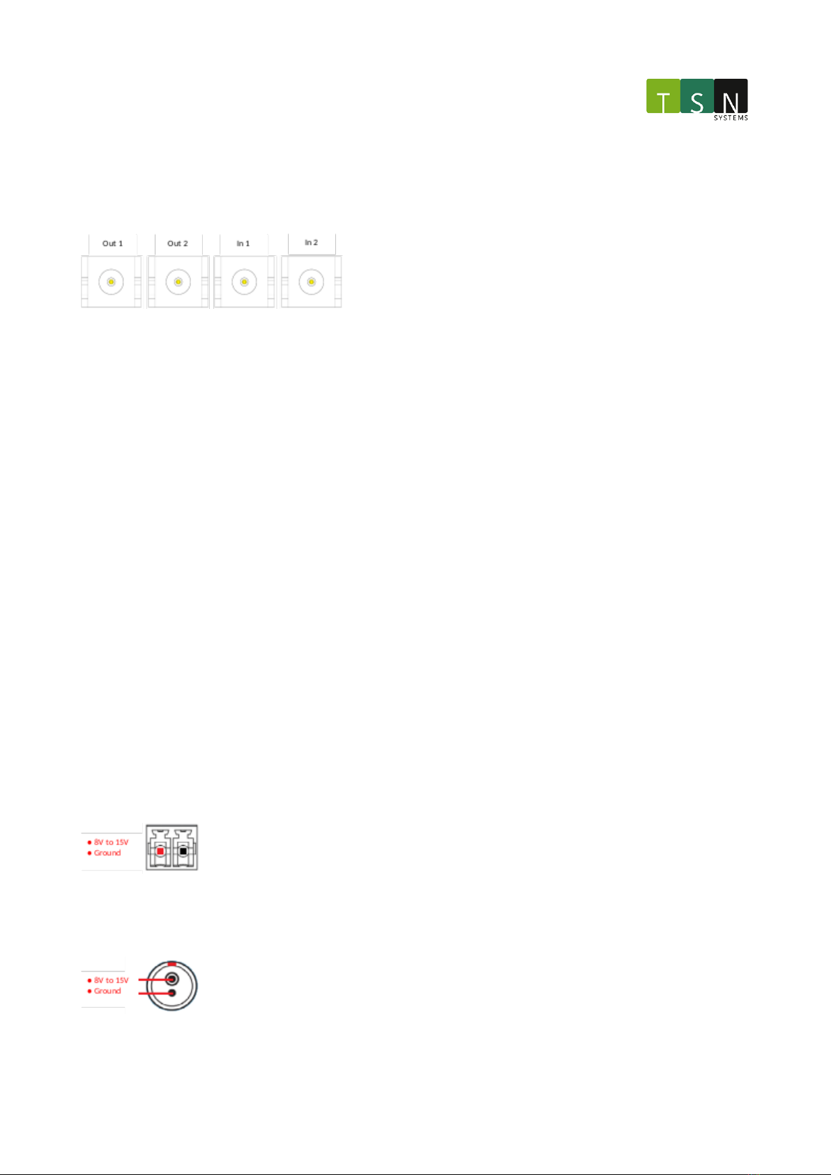
2.4.13 PPS IO
The PPS IO consists of 2x output channels and 2 input channels over 4x SMA connectors. These signals function
identically to the PPS channels on the SYNC board, including the 50Ωimpedance.
Each shell is connected to signal ground.
The electrical specifications are the same as theSYNC ModulePPSmodeabove.
2.4.14 Reset
This button is placed behind a pin hole, and can be reached with a pin at least 5mm in length. Using this button
causes a cold restart by triggering the reset pins on the FPGA and the host CPU.
2.4.15 Recovery Button
This button is placed behind a pin hole, and can be reached with a pin at least 5mm in length. This button is to be
used as emergency software recovery mode / factory restore.
2.4.16 Power
There are two power jacks on the unit, both directly electrically connected in parallel. The circular connector is a
specialized plug that mates with the accompanying power supply. The green Terminal Block Header can be used to
daisy chain multiple units. Acompatible connector is supplied.
Theinput voltage range is 8V minimum to 15V maximum.
The typical current load of the unitis 1.5A with a maximum load of 2.3A.
Ensure that the power supply can handle this maximum load when daisy chaining multiple units.
2.4.16.1 Terminal Block Header (Green)
The mating connector of the terminal blockpower connector is the Phoenix Contact1840366.
Circular Connector (Silver)

TSN Box Development – TSN Box 3.0 Getting Started Guide
Hardware – 17
2.4.17 Earth/Chassis
This connects directly to the unit'schassis. It is important to equalize the ground potentials of devices when using
T1 connections with isolated power supplies since the T1 connections are not isolated themselves, allowing
possible voltage transients to damage the T1 ports when a cable is connected. Always ensure that the unit has the
same ground potential to connected T1 devices by connecting the chassis to a ground/chassis connection of the
connected device(s).
2.4.18 Thermal Considerations
Always ensure that the two ventilation openings at the top of the unit is unobstructed.
At present temperature control is limited to the fan speed being set to a low static value after startup; dynamic
control shall be added in the near future. A very low fan speed was elected for minimal noise, yet still guaranteeing
safe operation at standard 20℃laboratory conditions with acceptable margin.
If the unit is to be operated at elevated ambient temperatures, please contact support for appropriate fan control
adjustment.
2.5 Software (Web based)
2.5.1 Prerequisites
•Host PC with a modern web browser.
•CAT5e/CAT6 cable to connect the host PC to the unit.
2.5.2 Getting started
Power up the unit as described in the hardware chapter. Refer to the Hardware Setup Guide provided with the
unitto ensure the hardware is not configured in a potentially harmful manner.
2.5.3 Network discovery
By default, the unit you received has an IP address 192.168.41.XX/24 where XX are the last two digits of the unit's
serial number. In the event that the unit is booted into recovery mode using the recovery button, the unit's IP
address defaults to 192.168.41.250/24.
The unit has a web interface that can be used to configure and perform basic functions. The unit advertises itself
using Zeroconf <https://en.wikipedia.org/wiki/Zero-configuration_networking>_. Several tools are
available to discover the IP address of a board(s) connected to their LAN segment. If a python installation is
available, connected unitscan be discovered as follows:
from zeroconf import ServiceBrowser, Zeroconf

TSN Box Development – TSN Box 3.0 Getting Started Guide
Hardware – 18
class MyListener:
def remove_service(self, zeroconf, type, name):
print("Service %s removed" % (name,))
def add_service(self, zeroconf, type, name):
info = zeroconf.get_service_info(type, name)
print("Service %s added, service info: %s" % (name, info))
zeroconf = Zeroconf()
listener = MyListener()
browser = ServiceBrowser(zeroconf, "_http._tcp.local.", listener)
try:
input("Press enter to exit...\n\n")
except KeyboardInterrupt:
pass
finally:
zeroconf.close()
The output from the above will be:
Service tsnbox [xx:xx:xx:xx:xx:xx].http.tcp.local. added, service info: ServiceInfo(type='http.tcp.local.',
name='tsnbox [xx:xx:xx:xx:xx:xx].http.tcp.local.', address=b'xc0xa8),', port=38933, weight=0, priority=0,
server='tsnbox [xx:xx:xx:xx:xx:xx].http.tcp.local.', properties={b'ip': b'192.168.41.44', b'netmask':
b'255.255.255.0', b'type': False, b'devicemodel': b'tsnbox3', b'buildtype': False, b'tag': False, b'mac':
b'xx:xx:xx:xx:xx:xx', b'multicast': b'224.1.1.2', b'name': b'tsnbox', b'release': False})
From the info above, one can see that there is a unitrunning with IP address 192.168.41.44/24. This method will
discover any uniton the same LAN regardless of subnet. To connect to the unit, ensure that the PC's subnet
matches the one advertised; in this case, 255.255.255.0
For Windows, there are applications such as the Bonjour Browser <https://hobbyistsoftware.com/
bonjourbrowser>_ that can be used to search for running units.
2.5.4 Web Interface
Navigate to the IP address found from the discovery step above using a web browser to open a login page for the
web interface running on the unit. Current defaults are single user "admin" and default password "admin". The
following describes the sections in the web application.
Modules Configuration

TSN Box Development – TSN Box 3.0 Getting Started Guide
Hardware – 19
2.5.4.1 Packet generator:
This setup configures the unit to emit a best effort packet stream on port 1. The rate of packet generation and the
data contained in the packets is configurable by the user.
The setup sets the FPGA packet aggregation delay to zero.
For the packet generator, a packet can be specified in hex. The format of the hex is as follows:
22f00080b90000049f039d8a0001000000000000000003085fa03f06c420a00000009811bb1f47404218000001c00158818005214e0
93e01fff14c802a1ffc210a0ed9b77ffffd348682c180b0a02c280b05032260c0542e151388caa1308adedce3eff9f677f0f1fcfaef
aae3cf7bd7df9bcf10e06f52f41fa977e87dddde011d5b76f93cb264d31c7f47bd764e7fca122fd37e975b6837486bd44757d101e24
b75bcb82e1e79ab1d902fd589f8dea6eba76f62da21e1596eebc1ee525b49d02e01f4f0a703f7bc9c63558189df14252ad82c228920
af64e71b8046da029b5de4ca9811bb1f470042391100ffffffffffffffffffffffffffffffff8050228400a1a0c16828280b05c4c27
0a05828150a05426120a84c2a1318a9e739badfebbefce3a9eff192be3b9e78e59525d33855c08efbf3d2d9697b599a489e2c3c52cf
90fefbc4447b8e79fbd9699f17b865949bc09d3efdb368210d7415fab356b9c7eb4d7f0bd497a7b380fb6ff961fd61c8a70d49172fc
2b876d2c043928f06acf16d7f202d58e8fa004042f9d28442e94c442d04415cc8484405ac235202411526079a8d838a474041120000
01e00f8c81c00a314e096741114e0949f500000001095000000001019fad6a413f000f62553c01ea3bf3869df7ef9d2a04339f2f440
73fc800e2325a197c226d2fa44340932a8c7a34f304fbbb041c3cf994a72c9276e2c54a1173400697357d4a18691267c40ffe7249a6
051538bf17c57815d2d1c0479a6d06276d96d303edf34968cd484f8b566b81ee89cc271a2ddcd17ab52eb33e56fae9262ae24ba7b81
c4206da7be5a135dbb35297bcad6d8b4ec6bd0600e19a8d838a47004113b23d7af76c52c2987b4408fd4df23161a7932d374c11b06d
40e97e207469075fdf6bc5df2408c606c147276739fbac74b232361d676824849f5d9929d04cecbf7cb9e353159092657dd41874330
4c3bb235e35ab8f82d422c80acd73c4b212bdd616228742526230bb5feaf2af4b250c741c9606461c1c53e26bbe98532c0c4330a969
e4d071024870668ba79780f2b21581f30cd30c583b3be6816b08e9e7ee7ec477670d1a50e1923d0461f3a63c31cbf8b8ebd090bf496
5d81e79
This represents the entire frame. Wireshark can be used to export packets as hex and paste the output to the packet
generator. This involves right-clicking a packet in a Wireshark capture and selecting the option to copy the
frameasraw binary.
The packet generator will re-calculate the Ethernet frame's CRC before sending it out. The frequency of sending the
packets is set using the input field for "Time between packets".
TSN Box Development – TSN Box 3.0 Getting Started Guide
Hardware – 20
This setup sets the role for T1 port 1 to Master, the transmit source to fpga_tx, and the capture source to phy_rx.
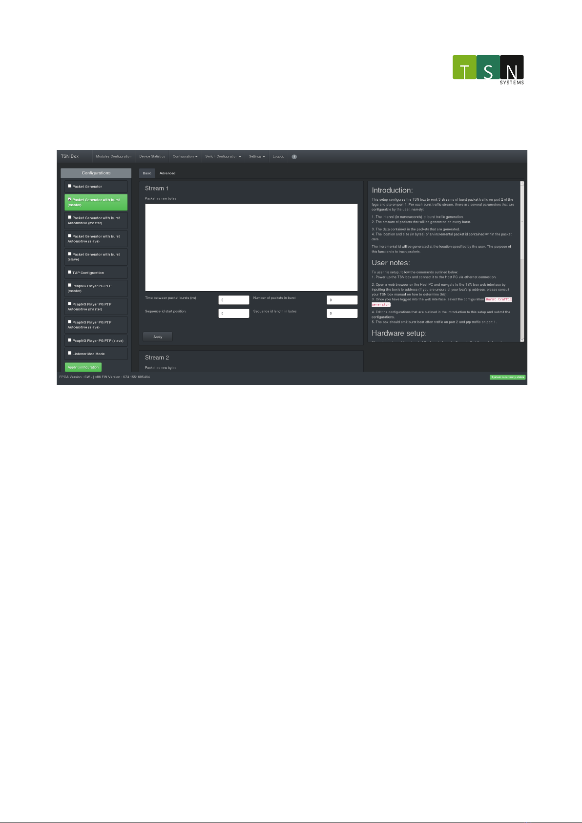
2.5.4.2 Packet generator with burst (PTP master)
This setup configures the unit to emit 3 streams of burst packet traffic on ports 1-3 and PTP traffic on port 4. For
each burst traffic stream, there are several parameters that are configurable, namely:
•The interval (in nanoseconds) of burst traffic generation.
•The amount of packets that will be generated on every burst.
•The data contained in the packets that are generated.
•The location and size (in bytes) of an incremental packet id contained within the packet data
This setup sets the roles for T1 ports 1-4 to Master. For ports 1-4 the transmit sources are set to fpga_tx, and the
capture sources are set to phy_rx.
This is similar to the packet generator configuration above but it has PTP running on port 4 configured to run as
master when used
in conjunction with the Packet generator with burst PTP slave configuration shown below.
Table of contents
Popular Inverter manuals by other brands


ROTOSOL
ROTOSOL INVERT RIS K Series user manual

Aqua
Aqua AQUA-STEAM GENERATOR 1 installation instructions

Energenie
Energenie EG-PWC-004 user manual

Kaco
Kaco blueplanet 3.0 NX3 M2 quick guide

Haier
Haier AS072XVERA Operation manual

Mitsubishi Electric
Mitsubishi Electric FR-F720-00046 Installation guidelines