Metal Fab Model M User manual

INSTALLATION AND MAINTENANCE
INSTRUCTIONS FOR LARGE DIAMETER
MODEL M GAS VENTS (B-VENT)
GENERAL:
The Model M Gas Vent has been designed for use with gas
burning Category 1 appliances. A Category 1 appliance
operates with a non-positive vent static pressure and with vent
temperature that avoids excessive condensate production in
the vent.
The vent is interconnected with a slip t and maintained with
sheet metal screws. The vent is of a double-wall construction,
with the inner ue of aluminum alloy (allowing rapid warm-up
and better draft) and the outer casing of galvanized steel or
galvalume steel.
SAFETY:
CAUTION: UL approval is based on using B-Vent
components supplied by Metal-Fab, Inc. Performance may
be affected and a safety hazard created if parts shown in
these instructions are not used.
1. This gas vent must maintain one-inch (25.4mm) clearance
to combustibles for sizes 16-inch (406mm) through 24-
inch (610mm). Two-inch (50.8mm) clearance to
combustibles is required for sizes 26-inch (660mm)
through 30-inch (760mm). DO NOT pack insulation or
other materials around the vent.
2. Use of draft increasers are limited to the exhaust end of
the vent system to maintain negative ue pressure.
3. Vent sizing is dened by tables in NFPA54 (ANSI Z223.1,
2002), or contact your Metal-Fab supplier. Install in
accordance with these instructions and local code
requirements.
4. Metal-Fab Type B Gas Vent and Fittings are to be used to
vent approved gas appliances intended to burn only gas.
Type B Vents are NOT to be used for the following:
A. Unlisted gas appliances
B. Incinerators
C. Recessed heaters
D. Conversion burners
E. Gas/oil burners
F. Any other appliance which may be readily converted
to a solid or liquid fuel.
G. Any other appliance not intended to burn only gas.
In areas where solid or liquid fuels are common, the
vent location should be marked “For use with vented
appliances burning only gas.”
5. Locate vent as close as possible to the appliances to
obtain maximum draft and to minimize connector pipe
length.
6. Maintain a pitch or rise from appliance to vent on
horizontal runs. Minimum rise is ¼” (6.4mm) to the foot.
7. A vent cap should be used on all installations to prevent
back drafts and to keep out rain and debris.
8. Venting into an unlined masonry chimney may cause
condensation. Install Type B Vent inside the chimney to
prevent condensation.
9. Do not install vent outside except where it is absolutely
necessary, and consult venting tables for proper design.
10. A gas vent support plate (MSP or MHS) is required if
vertical height exceeds 30’ (9144mm). Maximum of 30’
(9144mm) between supports.
11. When running vent through insulated areas, care must be
taken to prevent insulation from coming in contact with
the vent. This may be done by nailing headers between
joists through which vent is run, maintaining proper clearance
to combustibles or by nailing a restop on top of joists to
prevent insulation from falling into boxed area.
12. Other than in single or two family dwellings, when gas
vent extends through ceilings above the room with
appliance(s), the vent is to be enclosed with materials
having a re rating equal to or greater than oor, ceiling,
or roof.
13. It is not acceptable to penetrate the ue with screws
except when attaching drafthood to appliance outlet or
vent to single-wall connector.
INSTALLATION:
The Type B Gas Vent sections and associated components are
inserted one into another, then secured by sheet metal screws
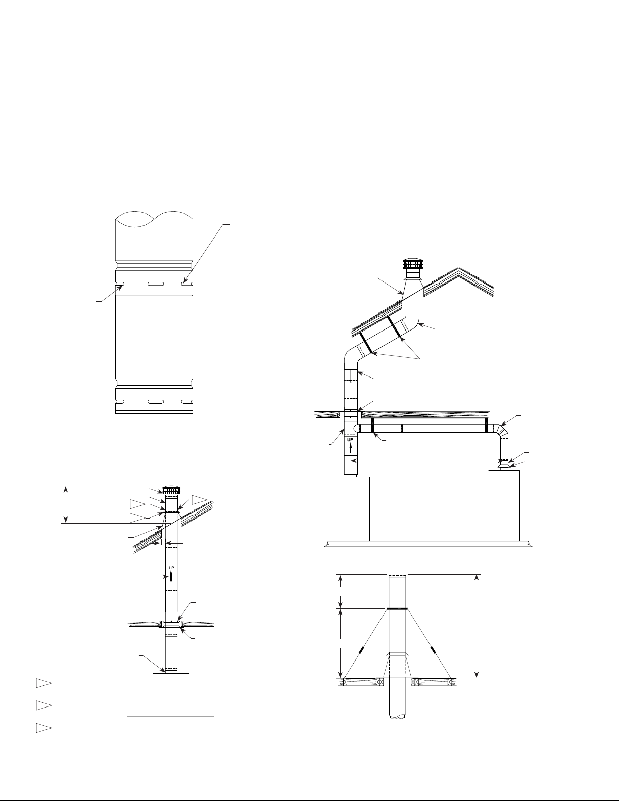
(#8 x ½(13mm)) provided with each section (See FIG. 1).
1. Starting at the appliance outlet or top of drafthood, attach
the rst section or component. Secure with screws
provided.
NOTE: Some appliances have the draft hood built into the
appliance. For these, the gas vent attaches directly to the
appliance outlet (See FIG. 2). If needed, a draft hood connector
(MDC) is attached to the appliance outlet.
2. Continue upward with the gas vent. If a oor is to be
penetrated, an MSP support plate or restop is required.
A eld fabricated restop is acceptable. To eld fabricate
a restop, use a 26-gauge galvanized steel plate. Cut a
hole slightly larger than the gas vent O.D. Position the
restop to maintain correct clearance to combustibles, then
nail in place.
NOTE: A MSP is required for every 30 feet (9144mm) of vent
stack to support the load.
3. When penetrating the roof, cut hole to maintain clearance
to combustibles. The MF ashing and MSC storm collar
are used to cover the hole in the roof. Terminate the vent
using the MC cap. If vent is more than 6 feet above where
it penetrates the roof, additional support is required.
(See FIG. 4.)
NOTE: For Canadian installations, use cUL section, designated
with a sufx G, on vent sections exposed to atmosphere.
These symbols on the nameplate
means this product is listed by
Underwriters Laboratories Inc.
Listing No. MH7860
SIZES 16” (406MM) THROUGH 30” (760MM)
2
4. If the installation requires offsets, elbows are available. The
inclined run (distance between elbows) must be
supported every 5 feet (1542mm). Plumbers straps are
acceptable. Total lateral and horizontal length shall not
exceed 75 percent of total vertical height (See FIG. 3).
5. It is acceptable to use a tee (MT) to multi-vent appliances
into a common vent (See FIG. 3). A support plate (MSP),
or other method, is required to support the gas vent
weight above the tee. The horizontal run of the vent must
be supported every 5 feet (1524mm). If no vent enters the
bottom of the tee, a tee cap (MTC) is required to close the
tee.
FIG. 4
6. Because the available lengths of vents may not meet your
installation needs, an adjustable vent section (M18A)
may be needed. The male end of the adjustable section
engages in the same manner as the vent section, the female
end opens to accept the male end of the vent section, then
must be secured by tightening the clamp of the adjustable
section (See FIG. 3).
7. If the vent system must increase in size due to vent
capacity, use an appropriate increaser (MI). The increaser
is installed the same as any vent section.
This completes your installation. If assistance is required,
contact your Metal-Fab supplier.
MAINTENANCE:
Gas Vent System normally operates trouble free. Conduct a
yearly inspection of the system, and replace any damaged
parts.
NOTE: If extreme weather conditions occur, inspection of all
exposed vent items is necessary. Replace any damaged part.
©2003 Metal-Fab, Inc. Form No. L1258 - 07/18
9817
FIG. 1
NOTE: SEAT MALE END INTO
FEMALE END AND SECURE WITH
SHEET METAL SCREWS PROVIDED.
TYPICAL FOR ALL JOINTS.
CAUTION: IF OTHER SCREWS ARE
USED, MAKE SURE THEY DO NOT
PENETRATE FLUE.
#8X1/2" SCREW
USE PREPUNCHED
SLOTS AS TEMPLATE
TO DRILL HOLES FOR
SCREWS.
FIG. 2
1.
2. 3.
STYLE M VENT
MC CAP
FLASHING
2.0FT. (635MM) MIN.
MIN. OF 2.0FT. (635MM) ABOVE
ROOF OR PARTION OF BUILDING
WITHIN 10FT.
MAINTAIN CLEARANCE TO
COMBUSTIBLE THROUGH JOIST AREA.
ARROW ALWAYS AWAY FROM
APPLIANCE. FOR EACH SECTION.
MSP - REQUIRED FOR EVERY
30FT. OF VENT HEIGHT.
FIRESTOP - 26ga GAL. STL. LOCATE
OVER JOIST TO MAINTAIN CORRECT
CLEARANCE FROM VENT CASING
TO COMBUSTIBLE MATERIAL
[1"(25MM) FOR 16" THRU 24" DIA;
2"(51MM) FOR 26"DIA AND UP.]
MDC (IF REQUIRED)
SEE APPLIANCE
INSTRUCTIONS
1. APPLY CAULKING OR METAL-FAB
MST TAPE WHERE VENT PASSES
THROUGH FLASHING.
APPLY THICK RING OF CAULK-
ING OR METAL-FAB MST TAPE
AROUND VENT AS SHOWN.
SLIDE STORM COLLAR DOWN
INTO CAULKING OR TAPE RING.
2.
3.
FIG. 3
SUPPORT EVERY
5FT(1524MM)
OF LATERAL RUN
M12A OR M18A (USED TO ADJUST FOR VARYING LENGTHS)
MSP [REQ'D ABOVE TEE AND EVERY 30FT. (9144MM)]
SEE FIGURE 2
FOR TERMINATION
M45 QTY. 2
MDC
DRAFT HOOD
M45
KEEP HORIZONTAL LENGTH
SHORT AS POSSIBLE
FOR GOOD DRAFT
SUPPORT EVERY
5FT(1524MM)
OF LATERAL RUN
NOTE: TOTAL OF HORIZONTAL LENGTH
AND INCLINED LENGTH CANNOT
EXCEED 75% OF VERTICAL LENGTH
MT
(MTC IF NO
BOTTOM ENTRY)
2/3
2/3
IF OUTLET EXCEEDS 6FT.
ABOVE ROOF. USE PIPE
BRACING OR CABLE GUYING.
NOTE: MAXIMUM UNSUPPORTED HEIGHT
FOR ALL DIAMETER SIZES IS 6FT.
APPLIANCE
APPLIANCE
#2
APPLIANCE
#1
Other Metal Fab Ventilation Hood manuals

Popular Ventilation Hood manuals by other brands

Gorenje
Gorenje S3 IHGC963S4X manual

KOBE
KOBE ISX2136SQB-1 Installation instructions and operation manual

U.S. Products
U.S. Products ADVANTAGE-100H Information & operating instructions

Kuppersberg
Kuppersberg DUDL 4 LX Technical Passport

Framtid
Framtid HW280 manual

Thermador
Thermador HGEW 36 FS installation manual


