Metal Fab TEMP GUAR 14TG User manual

*Combustible material is dened as material made of, or surfaced with, wood, compressed paper, plant bers,
plastic, or other material that will ignite and burn, whether ame proofed or not, or whether plastered or unplastered.
The Metal-Fab Temp/Guard Chimney is intended for use on any residential and building heating appliance burning gas, liquid or solid
fuels such as replace stoves, furnaces, ranges, room heaters, or as dened in columns I and II, Table 2-2.1, NFPA 211. Contact Local
Building or Fire Ofcials about restrictions and Installation Inspection in your area.
WARNING: Metal-Fab Temp/Guard Chimney is not designed for use on products that operate at continuous temperatures in
excess of 1,000°F.
1700°TEMP/GUARD CHIMNEY
SIZES 14” - 16” - 18”
TEMP/GUARD®
INSTALLATION AND MAINTENANCE
INSTRUCTIONS
This symbol on the nameplate
means this product is listed by
Underwriters Laboratories Inc.
Listing No. MH 8251
Tested to 103
A MAJOR CAUSE OF CHIMNEY RELATED FIRES IS FAILURE TO
MAINTAIN REQUIRED CLEARANCES (AIR SPACES) TO COMBUSTIBLE
MATERIAL.* MINIMUM CLEARANCE FOR 14”, 16” & 18” TEMP/GUARD IS
TWO (2) INCHES. IT IS OF UTMOST IMPORTANCE THAT THIS CHIMNEY
IS INSTALLED ONLY IN ACCORDANCE WITH THESE INSTRUCTIONS.
IMPORTANT: FOR OIL OR COAL BURNING APPLIANCES, OUTSIDE THE ENVELOPE OF THE BUILDING, USE ONLY PIPE WITH
STAINLESS STEEL CASING, ALSO USE FLASHING OR STORM COLLARS CONSTRUCTED OF STAINLESS STEEL OR ALUMINUM.
OPERATIONAL PRECAUTIONS
• Maintain 2” minimum clearance to combustibles for 14”, 16” & 18” diameters. (Refer to WARNING above). Use only U.L. Listed
products and INSTALL ONLY IN ACCORDANCE WITH MANUFACTURER’S INSTRUCTIONS.
• Formation of Creosote and Soot and the need for removal.
When wood is burned slowly, it produces tar and other organic vapors, which combine with expelled moisture to create
creosote. The creosote vapors condense in the relatively cool chimney ue of the slow burning re. As a result, creosote
residue accumulates on the ue lining. When ignited, this creosote makes an extremely hot re. The chimney should be
inspected at least once every two (2) months during the heating season to determine if a creosote or soot buildup has
occurred. If creosote or soot has accumulated, it should be removed to reduce the risk of chimney re.
• Do not use replace for food grill. Grease from foods can collect in chimney causing replace to become a potential re
hazard.
• On airtight stoves, open dampers and let equipment burn hot for 15 to 20 minutes. This should be done every time fuel is added.
This lessens the chance of creosote buildup.
• Some chemical chimney cleaners can be harmful to the chimney. These cause accelerated oxidation or corrosion. If chemical
cleaners are used, they must be non-corrosive in nature. If brush is used, it must be of proper size with plastic bristles.
• The 14TG, 16TG and 18TG chimney system is to be installed through a chase and not intended to pass through attic areas that
require insulation shields.
• Except for installation in one- and two-family dwellings, a factory-built chimney that extends through any zone above that on
which the connected appliance is located is to be provided with an enclosure having a re resistance rating equal to or greater
than that of the oor or roof assemblies through which it passes.
• Enclose exterior mounted chimneys below the roof line in geographical areas experiencing sustained low ambient temperatures
to help reduce or limit condensation, creosote and poor draft.

2
ANCHOR
EMBEDDED
IN MORTAR
L944 FIG15A
NOTE:
ANCHOR PLATE MOUNTED
AT MASONRY FIREPLACE
FLUE OPENING AREA
WITH, BOLT, NUTS, AND
WASHERS
ANCHOR PLATE
(CAT. NO. TGAP)
BED
OF MORTAR
FIG. 1
FIG. 2
CHIMNEY ASSEMBLY
The 14TG, 16TG and 18TG chimney system is designed for
quick and easy installation. The ue and casing assemble at
each joint using a male to female slip t. Each joint is secured
together with four (4) each sheet metal screws at the casing
(See FIG. 1).
MASONARY FIREPLACE CHIMNEY,
AND CHIMNEY EXTENSION
An anchor plate (TGAP) is used to attach Metal-Fab 1700°F
Chimney to a masonry replace or chimney. Maximum
support height of 50 ft.
1. Where the transition is to be made, apply a bed of mortar
approximately 3/4 inches deep and approximately one
(1) inch larger than the anchor plate. (See TG Chimney
Catalog for anchor plate dimensions).
2. Insert four (4) 1/4-20 x 2” anchor bolts, head down into the
mortar bed. J-style anchor bolts are preferred. An alternate
method would be to allow the mortar bed to cure. Then, drill
four (4) holes, matching the holes in the anchor plate and
insert four (4) each 1/4-20 metal anchors. The anchor plate
would then be attached by four (4) each 1/4-20 bolts.
3. Before the mortar sets, place the anchor plate over the bolts
and press down into the mortar. Loosely secure using a
washer and nut on each bolt.
4. Use a level to check the installation, assuring that the TG
chimney connection (TGAP) is level.
5. When the mortar has set up, tighten the nuts onto the bolts.
Proceed to stack Metal-Fab chimney pipe (TG) on the
anchor plate (See FIG. 2 and TABLE 1 for framing
dimensions).
6. See “Flashing Instructions” and “Termination” sections.
NOTE: Existing masonry ues may be extended with TG pipe
by using an anchor plate, following steps 1 through 6 above,
provided that (See FIG. 3):
a) The existing masonry chimney is structurally sound,
and;
b) The ue extension is properly sized so that the
appliance attached to the ue drafts properly.
NOTE: The TG ue size for a height less than 15 feet should be
at least 1/8 the area of the replace opening. The TG ue size
for a height over 15 feet should be at least 1/10 the area of the
replace opening. (For sizing of TG ue, See Metal-Fab literature
L1372.)
FIG. 3
TABLE 1
14", 16" & 18" DIAMETER FRAMING DIMENSIONS
FOR FLOOR, CEILING & ROOF OPENINGS
14" 21"x 21"
16" 23" x 23"
18" 25" x 25"
3
L944 FIG17
C
B
A
FIG. 5
FIG. 4
L944 FIG18
NAILNAIL
SUPPORT BAND/
PLUMBERS
STRAP
4’ MAX.
4’ MAX.
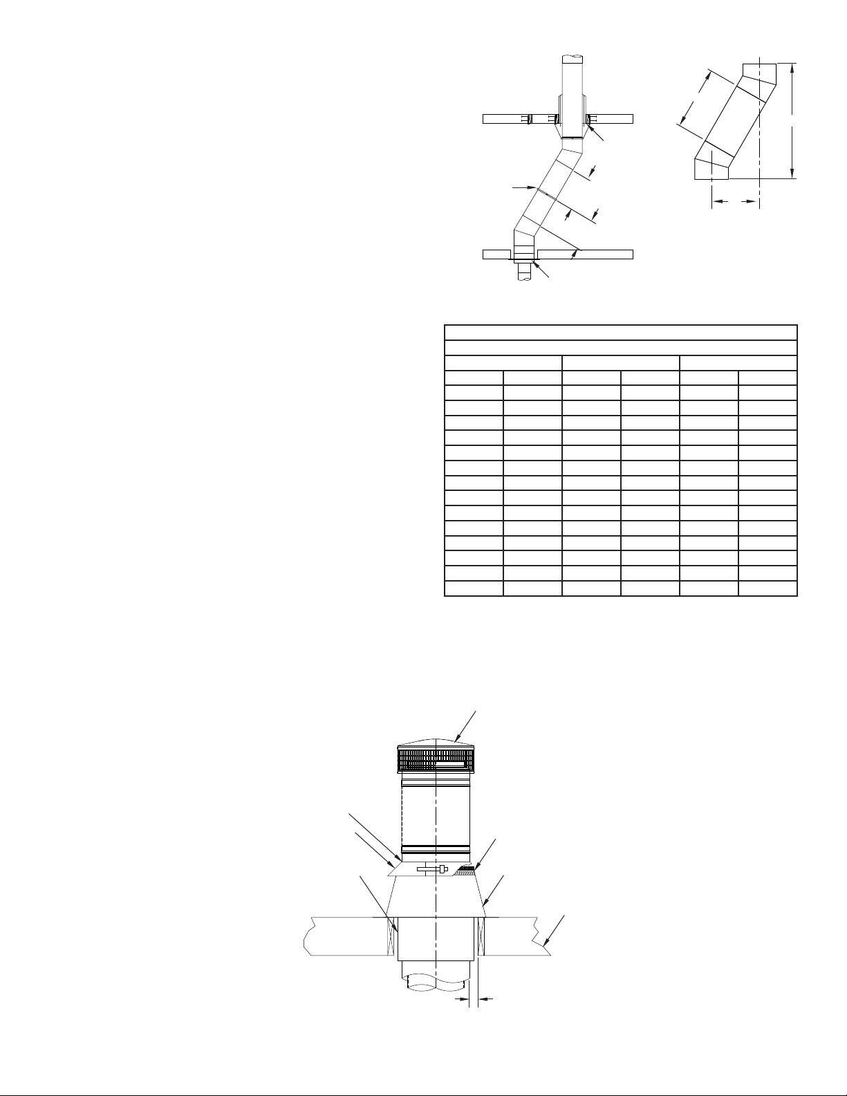
ELBOW INSTALLATION
1. 15° (TGA15) and 30° (TGA30) elbows are provided to allow
chimneys to avoid framing member or roof peaks. A
maximum of 30° from the vertical is allowed, and a total of
four elbows (two pair) for each chimney installation Maintain
2” clearance to combustibles for 14”, 16” and 18” diameters.
2. Attach the elbow to the chimney pipe or other support part.
Using the offset chart, add chimney sections between
elbows. A support band or plumbers strap is required every
4 foot interval between elbows to support the load as
shown in FIG. 4. Attach the upper elbow to bring chimney
back to vertical. See Table 2 and FIG. 5 for offset
combinations.
FLASHING INSTALLATION
1. Continue the TG chimney to the roof. Cut the roof opening,
centered over the chimney. A 2” airspace around
the chimney is required as it penetrates the roof
(See FIG. 6 and TABLE 1 for construction and framing
dimensions).
2. Install the next TG chimney section through the roof and
install the ashing (TGF) around the chimney and centered
over the roof penetration opening.
NOTE: If your roof is already shingled, be sure to slide the upper
edge under the shingles to prevent leakage.
3. Install a radiation shield (TGRSH) over the chimney
section and center the radiation shield within the joist area.
Bend straps of radiation shield over the top edge of ashing
to position in place. Apply a bead of caulk around the pipe at
the top edge of the ashing screen. Wrap the Storm Collar
around the pipe and imbed the edge of caulk to prevent
leakage around pipe. Bend the ashing strap around the tab
to tighten around the chimney (See FIG. 6).
4. Continue to install pipe sections until proper termination
height is reached. See termination section.
TABLE 2
14", 16" AND 18" DIAMETER OFFSET TABLE
A15 Angle 30 Angle
Length No. Pcs BCBC
0" 0 20-1/4" 2-1/2" 23-1/8" 5-7/8"
12" 1 30-1/2" 5-1/4" 32-1/4" 11-1/8"
18" 1 36-3/8" 6-3/4" 37-1/2" 14-1/8"
24" 1 42-1/8" 8-3/8" 42-5/8" 17-1/8"
30" 2 46-1/2" 6-1/2" 46-5/8" 19-3/8"
36" 1 53-3/4" 11-1/2" 53" 23-1/8"
42" 2 58-1/4" 12-5/8" 57" 25-3/8"
48" 2 64" 14-1/4" 62-1/4" 28-3/8"
54" 2 69-3/4" 15-3/4" 67-3/8" 31-3/8"
60" 2 75-5/8" 17-1/4" 72-5/8" 34-3/8"
72" 2 87-1/8" 20-3/8" 83" 40-3/8"
84" 3 97-3/8" 23-1/8" 92-1/4" 45-3/4"
90" 3 103-1/4" 24-3/4" 97-3/8" 48-3/4"
96" 3 109" 26-1/4" 102-5/8" 51-3/4"
FIRESTOP W/ INTEGRAL
RADIATION SHIELD
FIRESTOP
ROOF JOISTS
FLASHING (TGF)
FLASHING VENTS AND
SCREEN STAND OFF
TERMINATION CAP (TGC)
RADIATION SHIELD
BEND STRAPS OVER
FLASHING (TGRSH)
STORM COLLAR (SC)
CAULK
2” CLEARANCE TO
COMBUSTIBLES
FIG. 6
P.O. Box 1138 • WICHITA, KANSAS 67201
(316) 943-2351 • FAX (316) 943-2717
ECR 8852
L944 FIG22
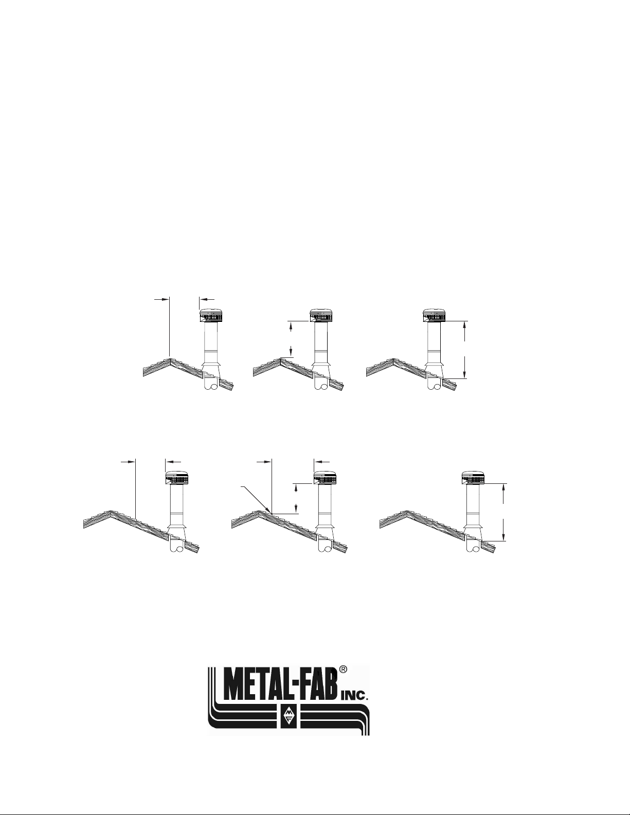
TERMINATION
Major building codes specify a minimum chimney height above
the roof top. These specications are summarized in what is
known as the “Ten Foot Rule”. This rule states:
If the horizontal distance from the side of the chimney to the peak
of the roof is 10 feet or less, the top of the chimney must be at
least 2 feet above the peak of the roof, but never less than 3 feet
in overall height above the highest point where it passes through
the roof (FIG. 7).
If the horizontal distance from the side of the chimney to the peak
of the roof is more than 10 feet, a chimney height reference point
is established on the surface of the roof a distance of 10 feet
from the side of the chimney in a horizontal plane. The top of the
chimney must be at least 2 feet above this reference point, but
never less than 3 feet in height above the highest point where it
passes through the roof (FIG. 8)
FIG. 7
IF 10
FEET OR
LESS
L944 FIG21
THEN BUT
MUST BE AT
LEAST 2 FEET NEVER LESS
THAN 3 FEET
FIG. 8
IF 10
FEET OR
MORE
MUST BE AT
LEAST 2 FEET NEVER LESS
THAN 3 FEET
10 FEET
REFERENCE
POINT
THEN BUT
These chimney heights are necessary in the interest of safety
and do not ensure smoke free operation. Trees, buildings,
adjoining roof lines, adverse wind conditions, etc., may create
need for a taller chimney should smoking occur.
Additional support is required above the roof if the chimney
height exceeds four (4) feet.
This manual suits for next models
2
Other Metal Fab Ventilation Hood manuals

Popular Ventilation Hood manuals by other brands

Gorenje
Gorenje S3 IHGC963S4X manual

KOBE
KOBE ISX2136SQB-1 Installation instructions and operation manual

U.S. Products
U.S. Products ADVANTAGE-100H Information & operating instructions

Kuppersberg
Kuppersberg DUDL 4 LX Technical Passport

Framtid
Framtid HW280 manual

Thermador
Thermador HGEW 36 FS installation manual


