Metallisation MK 73 User manual

HAZARD
RATING
Compressed Gases
*
Highly Flammable / Extremely flammable
gases. Hydrogen, Propane, Acetylene, LPG
and/or Oxygen (fire and explosion risk
***
Noise
**
Fine Dusts, fume and powders (explosion risk)
***
Potentially toxic consumables
***
Water borne disease (water curtain fitted)
*
Mechanical Hazard (automated equipment)
*
Burns
***
Stab Risk
*
If hose protection and flashback arrestors are fitted, the risk of flames
reaching the fuel gas and oxygen supplies is virtually eliminated.
However, if flashback is sustained, it can seriously damage the nozzle
assembly.
Flashbacks can be caused mainly as a result of poor maintenance,
missing or damaged seals, blocked or damaged nozzle parts.
Flashback
Immediately close the pistol valve.
Shut off the oxygen supply valve.
Shut off the fuel gas supply valve.
If fitted, operate the safety shut-off handle on the flowmeter.
Re-open the pistol valve and allow air to flush the nozzle
assembly for approximately 30 seconds to cool the nozzle
parts.
Open the oxygen and fuel gas supplies and check the gas
flows on the flow meter.
If the flows appear to be ok re-light the pistol.
If the flows are out of specification or if there is a repeat
flashback close the pistol down as above.
Remove and inspect the nozzle assembly as per
maintenance instructions.
If flashback occurs, the following procedure should always
be carried out:
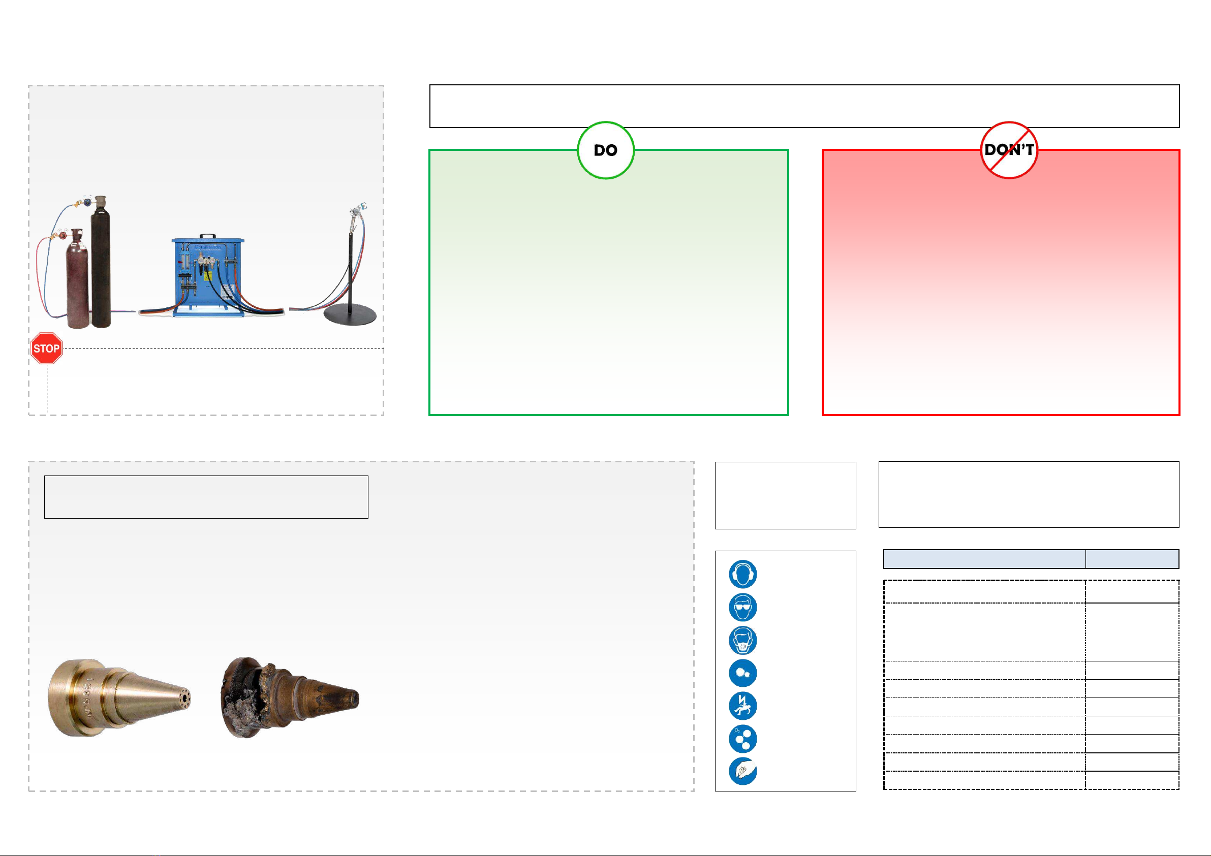
FIG 1. A good working
Nozzle.
FIG 2. A nozzle having
Incurred a flashback.
Approximate rating of the hazards in typical circumstances.
Hazard ratings may change in individual circumstances
Key
Hazards
Noise
Radiant Energy
Fume & Dust
Mehanical Hazards
Electrical Hazards
Ozone
Material Handling
Equipment Dos and Don’ts
IMPORTANT
SAFETY
PRECAUTIONS
All appropriate safety precautions and risk assessments
MUST be carried out prior to and during use of the system.
These can be viewed in full in the complete MK61 / MK73
System Manual.
DO Check all hoses regularly. Damaged hoses must be replaced
immediately.
DO Ensure that all hose connections are properly tightened and do
not leak.
DO Ensure that proper extraction is available and is turned on
before the gas supplies are tuned on and turned off after the
gas supplies are turned off.
NEVER Point the pistol towards other personnel or combustible
material.
NEVER Spray onto hoses, regulators or flowmeters.
NEVER Operate the pistol without using ear defenders and the
appropriate eye protection.
NEVER Apply grease to any thread or connection which
is to carry oxygen.
NEVER Operate the pistol without using regulators
fitted with flashback arrestors.
NEVER Release gases into an un-extracted area.

Unpack and check all parts are present and undamaged.
Ensure that all hoses, fittings and components are clean and free
from damage.
1
2
Fit the fuel gas and oxygen regulators to their respective supply
lines or cylinders.
Fit the flashback arrestors to the fuel gas and oxygen regulators.
Ensure that all connections are properly made and gas tight.
If not using the board as a freestanding unit, fix the mounting panel
to a suitable vertical surface.
6
7
Fit the other ends of the hoses to the appropriate connections on
the pistol.
Supplies
MK73 Propene Hose shown
MK61 requires Acetylene hose (Red)
CONNECTING
THE
SYSTEM
All appropriate safety precautions and risk assessments
MUST be carried out prior to and during use of the system.
These can be viewed in full in the complete MK61 / MK73
System Manual.
Flowboard
Regulators &
arrestors
Pistol &
Toolkit
The pistol may be
provided with or
without the
spreader
Fit the oxygen and
fuel gas hoses to their
respective arrestors.
NB: The indents on
the fuel gas hose
indicate a left turning
thread.
Fit all hoses to their appropriate connections on the flowboard.
Some installations require in-line flashback arrestors to be fitted to
the outlet connections to the pistol.
4
3
5
TO
PISTOL
TO
REGULATORS
For easier access, fit the
the middle hose first (left
thread).
If fitted connect the oxygen hose to the
panel mount regulator instead of directly
into the manifold under the flowmeter.
Connect the inlet air hose to the
manifold
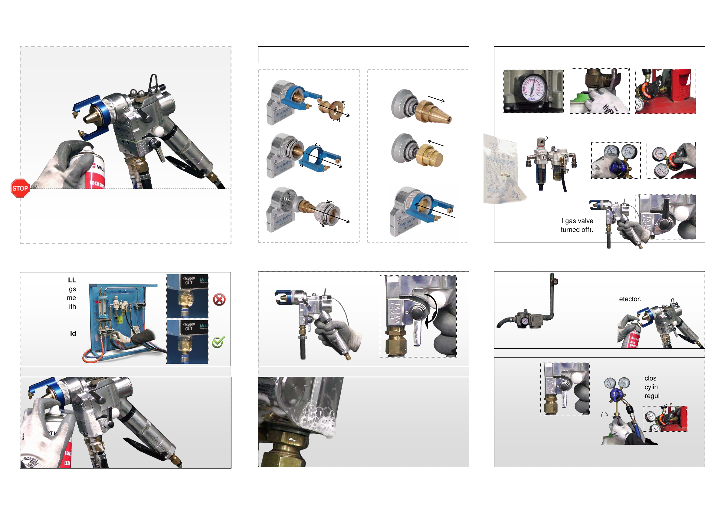
Fit leak test nozzle to the pistol.
2
Open air, oxygen and fuel gas valves
3
Spray ALL
unions / fittings
on the flame
spray board with
leak detector.
No leaks should
be visible.
Open the pistol gas valve (turned on).
5
7
Isolate the
air supply.
LEAK TEST PROCEDURE
Spray ALL unions / fittings &
cam spindle housing /
diaphragm housing / mixing
Ensure the pistol gas valve
is closed (turned off).
4
1
Regulate to recommended full system pressure (as per manual).
Spray unions / fittings & cam spindle
housing / diaphragm housing /
mixing block with leak detector.
AIR WILL BLEED through the cam
spindle housing & potentially
between the cam spindle housing /
diaphragm housing.
block with leak
detector.
No leaks
should be
visible.
6
Spray unions / fittings & cam spindle
housing / diaphragm housing / mixing
block with a leak detector.
No leaks
should be
visible.
8
Ensure the
pistol gas
valve is still
open
(turned on).
Isolate/
close
cylinder
regulators.
Observe regulators for pressure drop over 2 minutes - no pressure
drop should be seen if there is no gas leak.
The full leak test procedure must be carried out every 6 months as per routine maintenance,
after any maintenance before the pistol is lit and every time gas cylinders are changed.
Additionally, before every shift it is also best practice to leak test from the cylinders to the gun
using a leak detector spray.
NB: Before leak testing ensure all hoses are connected correctly and all gauges are in good
working order. Leak test information is based on the assumption that all pressure gauges are in
good working order, with any visible defects having already been rectified e.g. damaged hoses,
broken flowmeters etc.

Check the
ARF.
A
NB: 90% of coating failures are a result of poor substrate preparation. These
general rules should be followed prior to spraying:
1
A. Check that the ARF filter bowl is empty and clean. If not remove and clean.
B. Check the ARF lubricator bowl. Top up lubrication oil if low, clean out and
refill if oil is contaminated.
NB: Should be set to 1 drop per 20 to 30 seconds.
2
B
6
Turn on the extraction system and ensure it is operating correctly.
Open the Drive Rollers and feed wire into the gun until it protrudes
from the Air Nipple.
4
Ensure the pistol gas valve is fully open.
5
Set the regulator pressures as per the parameter settings for
the size of wire being sprayed. See full operation manual for
more details.
Check the flow meters and adjust
the oxygen regulator if the flows
are slightly out of specification.
DO NOT adjust fuel gas.
For extended supplies adjust using
the board mounted regulator.
Flow differentials are important. If
the errors are excessive inspect
the nozzle assembly.
OPERATING THE SYSTEM
PART 1
Pull down
and twist to
remove
bowl
Before attempting to spray, leak test the system. Also, every time the system is
assembled and/or at least once per week.
• Workpieces must be prepared in accordance with the customers requirements.
• All surfaces to be sprayed should be degreased using a suitable degreaser.
• All surfaces should be GRIT blasted to the specification required by the customer.
Pull
down
and twist
Close the Drive Rollers.
3
Turn on compressed air, fuel gas and oxygen.
The pistol gas valve
can now be closed in
preparation for the
spraying process.
7

Draw the wire back until it is flush with the front of the nozzle
1
Note: Air nipple removed for clarity
End flush with nozzle
Cone shoulder flush with nozzle
OPERATING THE SYSTEM
PART 2
• Workpieces must be prepared in accordance with the
requirements.
• All surfaces to be sprayed should be degreased using
a suitable degreaser.
• All surfaces should be GRIT blasted to the
specification required by the customer.
NB: 90% of coating failures are a result of poor substrate
preparation. These general rules should be followed prior
to spraying:
It is important that the valve lever is turned to the
fully open position. Also a steady action is important
- Opening too slowly will burn out the Air Nipple. Too
fast will blow out the flame.
If the flame is not burning correctly adjust the
oxygen flow at the supply regulator (DO NOT adjust
fuel gas). For a long hose system (i.e. 3/8” hoses)
adjust the oxygen flow at the board.
When the pistol is alight, the flowmeter floats will
change position. This is normal DO NOT try to re-
adjust parameters to get the flowmeter floats to the
‘before lighting’ settings.
Horizontal
fan
Vertical
fan
Aligned with groove
= narrow round spray
Counter
clockwise
to increase
speed
Poor spray angle:
Wastes material
Poor adhesion
Good spray angle:
Good adhesion
Maximum deposits
To extinguish turn the pistol valve to the
OFF position (180° anti-clockwise in a
single smooth movement) but hold the wire
feed trigger for approximately 1 second
longer. NOTE: Turning the valve too slow
can cause damage to the pistol.
If the pistol is not going to be used for a period of time the gas
must be switched off and the hoses drained.
WARNING: The Spreader should always be turned in an anti-clockwise
direction (operator POV). Rotating in a clockwise direction could loosen
the air cover, potentially resulting in damage being caused.
Pull the trigger and adjust the wire speed until an acceptable sharp point of
wire is protruding from the Air Nipple (approx. 3 times the wire diameter).
clockwise to
reduce
speed
If fitted adjust the spreader to give the desired direction of the spread.
Note: There is a position where air to the spreader jet is cut off.
If the spreader is not required, rotate spreader until it shuts off.
Spray perpendicular to the work.
Stand-off distance 4”-8” (100-200mm) travelling at a suitable pace.
Shut off the gas and oxygen at the supply points.
Open the pistol valve to allow the lines to empty.
Shut off the air at the supply point.
ONLY when these steps have been complete
should the extraction system be turned off.
Extinguishing the Pistol
2
3
4
5
Depress the lever and turn to the pilot position.
Turn until it stops (approximately ¼ of a turn).
Light the pistol and
allow the flame to stabilise.
Turn gas control lever to the fully open position using
a smooth steady action.
Pull the wire feed trigger to spray.
Note: the different flame colour when spraying.
General good
spraying practice.
Before attempting to spray, leak test the
system. Also, every time the system is
assembled and/or at least once per week.
GENERAL MAINTENANCE
In order to prevent the ingress of any dirt, ensure that any further disassembly is
carried out in a clean environment and ensure that as a minimum the following
spares are available: Part Number: GAS-SSP -MK61 / MK73 Standard Spares
Pack for Gas Systems.
As part of the routine maintenance, the system should also be leak tested at
least every time the system is assembled and once per week
It is good practice to follow the below maintenance procedure,
after every 8 hours of use:
Clean the outside of the pistol to remove adherent dust.
Remove the air nipple and clean the inside cone, taking
care not to scratch or otherwise blemish the surface.
Instruction on disassembly of the Gas Head is found in the
next section of this guide.
Clean exposed surface of the wire nozzle carefully, again
taking care not to scratch or otherwise blemish the surface.
Check hose connection and hose condition and replace any
connection or hose as necessary.
Drain the ARF and top up / clean the lubricator.
GENERAL ROUTINE MAINTENANCE
AIR MOTOR ROUTINE MAINTENANCE
Daily: Lubrication is vital to reduce wear, friction and corrosion
of internal parts, therefore check the oil lubricator level and fill up
as required.
Note: Dirt particles can cause serious damage. Air should be filtered to
5 micron or less.
Most compressed air systems contain some moisture; if this is allowed
to remain in the motor internal corrosion can cause the motor to seize.
Condensation in the motor is aggravated when the atmosphere is damp
and the working conditions are cold. Since air cools as it expands
within the motor, periods of continuous operation can make the motor
cold and increase the condensation risk, so where this is thought to be
a danger it may be wise to run the motor for several seconds once the
body is no longer cold to the touch, in order to blow through any
droplets.
If the motor is to be left for a few days or stored, put a few drops of light
oil in the air inlet and rotate the motor slowly for a few seconds to
protect the internal parts.
Don’t drop the motor! Internal clearances can be upset by mishandling, and this will cause the motor to run slow
or even stall.
If a motor is tight, usually an injection of WD40 in the air inlet with lever depressed will help. Leave it to soak for 15
minutes before attempting to start the motor. WD40 is not a good lubricant, so once free the motor must be
lubricated.
Use the recommended oil in the oil lubricator unit. Compressor or hydraulic oil is NOT suitable.
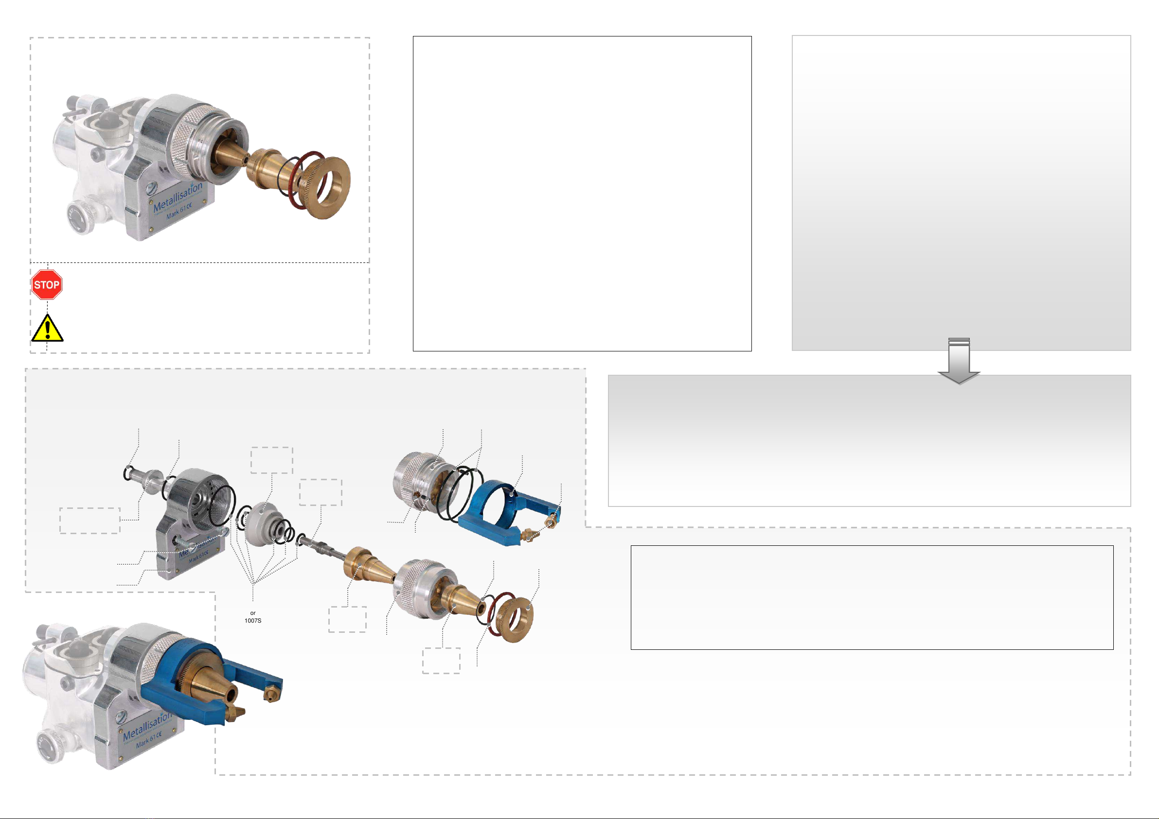
GAS HEAD PARTS & DISCONNECTING THE PISTOL
DISCONNECTING THE PISTOL
Extinguish the pistol.
Ensure that all supplies to the pistol are turned off and that the gas lines have been emptied.
Disconnect all hoses at the pistol. Do not allow the hose ends to fall to the floor or be contaminated with dust.
Coil up the hoses and hang them in a safe place.
Leave the pistol valve open to avoid damaging the internal diaphragms.
The Nozzle Assembly should only be dismantled when it is absolutely necessary. For example:
If it is dirty/worn.
If it is damaged.
When needing to change the Wire Diameter.
1007
1008
1029
1250
NOZZLE
INSERT
FRONT WIRE
GUIDE
NOZZLE
SHELL
1017
1025
1063
1066
1252
or 1257
1253
1065
6021
AIR
NIPPLE
1254
1024
10073S
or
1007S
MIXING
BLOCK
METALLISATION LIMITED
Pear Tree Lane,
Dudley, West Midlands,
DY2 0XH, UK
Tel: +44 1384 252464
Fax: +44 1384 237196
The information in this manual was correct at the time of publication; Metallisation disclaims liability for any
inaccuracies or omissions that may have occurred. Periodically, changes are made to the information herein, and
Metallisation reserve the right to make improvements and/or changes to the products described in this publication
at any time without prior notice.
Other manuals for MK 73
1
This manual suits for next models
1
Table of contents
Other Metallisation Paint Sprayer manuals


Popular Paint Sprayer manuals by other brands


Milwaukee
Milwaukee M18 BPFP-CST Original instructions

Worcraft PROFESSIONAL
Worcraft PROFESSIONAL SG06-800 manual

Solo
Solo 424 NOVA Operator's manual & parts list

Birchmeier
Birchmeier Spray-Matic 1.25 P operating manual

Anest Iwata
Anest Iwata AL-96 S5 instruction manual

Graco
Graco REACTOR 246024 Electrical diagrams


