Metallisation ARC150-2310D User manual

Page 1of 48
ssue: 21/11-11

Page 2of 48
Issue: 15-09-2015
This operating manual must be read and understood before any
attempt is made to operate the equipment described herein. In
particular, refer to the Safety Warnings / Risk Assessments in
Section 1.
Under no circumstances should any modifications be made to
the equipment without prior written approval from Metallisation.
MAN-ARC150-OP
For Pistols: ARC150-CG23
ARC150-CG25
For Energiser: S500-PLC
Related Manuals:
Pistol Maintenance Manual:
MAN-ARC150-MA
Energiser Maintenance Manual:
MAN-ENE-S500(150)

Page 3of 48
SPECIFICATIONS
The Metallisation ARC150/S500-PLC Arc Spray System is designed for anti-corrosion coatings and will
give consistent throughputs with high coating quality.
The following specification covers the standard range of ARC150 Pistol with S500-PLC (ARC150)
Energiser with closed loop current control.
The Pistol Pistol Rating - Max Current: 500 Amps
Dimensions:
WEIGHT
LENGTH
HEIGHT
WIDTH
STAND ALONE
INC. CABLE &
HOSES @ 1.2M
275mm (10.8”)
240mm (9.4”)
102mm (4”)
2.1kg (4.65lb)
5.1kg (11.24lb)
The Energiser (S500-PLC)
Dimensions:
LENGTH
HEIGHT
WIDTH
WEIGHT
900mm (35.4”)
800mm (31.5”)
875mm (34.5”) To Handle
485mm (19.1”)
670mm (26.4”) Wheel to Wheel
291.6kg (644lb)
S500-PLC Energiser Specification:
DESCRIPTION
CHARACTERISTICS
Input Power Requirements
380/415/460 Vac 50-60Hz 3 Phase
Optional Input Power
220V 50-60Hz 3 Phase
Fusing Required
37A @ 460 Vac
40A @ 415 Vac
44A @ 380 Vac
76A @ 220 Vac
84A @ 200 Vac
Max Power Consumption
29 KVA (46Vdc/500A output)
Typical Power Consumption
16 KVA (Zinc 26Vdc/500A output)
22 KVA (Aluminium 35Vdc/500A output)
Duty
0-500 AMPS @ 100% Duty Cycle
Output Voltage
0-49 Vdc Switched High/Low & 1 –5
(Nominal Spray Voltage 19 to 44Vdc)
Air Requirements
1.5m³ /min @ 5 bar (53cfm @ 72.5 psi)
Power Factor
0.85 Lag
Auxiliary Circuits
110Vac and 24Vdc
Pressure Switch Setting
30 psi (2.0 bar)

Page 4of 48
CONTENTS
SECTION 1
SAFETY PRECAUTIONS & RISK ASSESSMENTS................................................................................6
1.1 Safety Precautions......................................................................................................................................7
1.1.1 Equipment Dos and Don’ts.......................................................................................................................7
1.1.2 Handling of the Energiser.........................................................................................................................7
1.1.3 The Energiser Mains Supply ....................................................................................................................7
1.2 Risk Assessment........................................................................................................................................8
1.3 Key Hazards...............................................................................................................................................9
1.3.1 Noise........................................................................................................................................................9
1.3.2 Radiant Energy ........................................................................................................................................9
1.3.3 Fume & Dust..........................................................................................................................................10
1.3.4 Mechanical Hazards............................................................................................................................... 12
1.3.5 Electrical Hazards ..................................................................................................................................12
1.3.6 OZONE..................................................................................................................................................12
1.3.7 Material Handling ...................................................................................................................................13
1.3.8 The Pistol...............................................................................................................................................13
1.3.9 Summary................................................................................................................................................13
SECTION 2
THE EQUIPMENT ..................................................................................................................................14
2.1 System Configurations..............................................................................................................................15
SECTION 3
OPERATING THE EQUIPMENT ............................................................................................................17
3.1 Connecting the System.............................................................................................................................18
3.2 Connecting using a Powered Extension Trolley ........................................................................................20
3.3 Preparing to Spray....................................................................................................................................22
3.4 Spraying ...................................................................................................................................................24
3.5 Shutting Down ..........................................................................................................................................26
3.6 Remote Pendant.......................................................................................................................................26
3.7 Using Optional Arc Extension ...................................................................................................................27
3.8 Closed Loop and Open Loop Modes.........................................................................................................27
SECTION 4
BASIC MAINTENANCE..........................................................................................................................28
4.1 Routine Maintenance................................................................................................................................29
4.2 CG Spray Head –Checking Contact Tips................................................................................................. 30
4.3 CG Spray Head –Complete Disassembly ................................................................................................32
4.4 CG Spray Head Reassembly....................................................................................................................34
4.5 Tension Adjustment of Rollers..................................................................................................................36
4.6 Roller Guide Assembly Maintenance ........................................................................................................37

Page 5of 48
4.7 Rear Wire Guides - Checking ...................................................................................................................38
4.8 Supplies & Manifold Maintenance.............................................................................................................39
4.9 Wire Condition..........................................................................................................................................40
SECTION 5
FAULT FINDING.....................................................................................................................................41
5.1 Operational Troubleshooting.....................................................................................................................42
SECTION 6
ILLUSTRATED PARTS LIST .................................................................................................................43
6.1 Main Components.....................................................................................................................................44
6.2 CG Spray Head.........................................................................................................................................45
SECTION 7
INFORMATION TABLES .......................................................................................................................46
7.1 Typical Performance Figures ....................................................................................................................47

Page 6of 48
SECTION 1
SAFETY PRECAUTIONS & RISK ASSESSMENTS
1.1 Safety Precautions
1.1.1 Equipment Dos & Don’ts
1.1.2 Handling of the Energiser
1.1.3 The Energiser Mains Supply
1.2 Risk Assessment
1.3 Key Hazards
1.3.1 Noise
1.3.2 Radiant Energy
1.3.3 Fume & Dust
1.3.4 Mechanical Hazards
1.3.5 Electrical Hazards
1.3.6 OZONE
1.3.7 Material Handling
1.3.8 The Pistol
1.3.9 Summary

Page 7of 48
1.1 Safety Precautions
Provided that the equipment is properly set up, regularly maintained and used correctly, metal
spraying does not present any great danger. However, like most industrial processes, misuse
and careless practices can create hazards for personnel and damage to the equipment.
The equipment detailed in this manual will produce levels of noise, UV light and dust that
require safety measures to be taken by personnel using the equipment. Careful consideration
should be taken when positioning this equipment.
It is the responsibility of the user to ensure that all appropriate measures are in place for safe
operation, before the equipment is used. Metallisation will be pleased to assist and advise as
appropriate.
1.1.1 Equipment Dos and Don’ts
Ensure that all appropriate Risk Assessments are carried out before using this equipment.
Ensure the equipment is properly set up as per Section 3.1 of this Manual.
NEVER point the pistol towards other personnel or combustible material.
NEVER spray onto hoses, cables or instruments.
NEVER operate the pistol without using ear defenders and the appropriate eye protection.
NEVER look into the arc zone, without first ensuring that the power switch is in the "off"
position and the drive motor is switched off.
1.1.2 Handling of the Energiser
The Energiser must only be lifted from the base, under no circumstances should it be lifted by
the handle or by the M12 thread that locates the dispenser spigot.
Care must be taken if attempting to transport the Energiser by fork lift truck not to damage the
underside of the unit.
1.1.3 The Energiser Mains Supply
The mains supply MUST be disconnected before removing any of the outer panels.
Isolate the mains supply.
ALL maintenance or overhaul should be conducted by a fully qualified electrician in
accordance with local regulations.

Page 8of 48
1.2 Risk Assessment
Prior to commencing work with Thermal Spray equipment, a Risk Assessment should be
carried out on the equipment and the way in which that equipment is to be used.
The Risk Assessment should identify the hazards associated with the work and also the
control measures required. This will either eliminate the risk, or reduce it to an acceptable
level to prevent ill health or injury to the persons carrying out, or who could be affected by the
work.
The results of the Risk Assessment and the control measures necessary should be made
known to the persons carrying out, or those affected by the work.
Some control measures are better able to produce the desired result than others.
The safety precedence sequence shows the order of effectiveness of measures.
Hazard Elimination
Use of alternative work methods, design improvements or change of process.
Substitution
Replacement of material/substance with another of less risk.
Use of Barriers
Isolation or segregation.
Use of Documented Procedure
Limiting exposure times, dilution of exposure. Safe systems of work that depend on human
response.
Use of Warning Signs
Signs, instructions, labels that depend on human response.
Use of Personal Protective Equipment (PPE)
Depends on human response, used as a sole measure only when all other options have been
exhausted. PPE is the last resort.
It is the responsibility of the user of the equipment to ensure that all appropriate control
measures identified in the Risk Assessment are in place before using the equipment.
To assist you in carrying out your Risk Assessment we have identified the Key Hazards in the
operation of Thermal Spray Equipment and this information can be found in Section 1.3.

Page 9of 48
1.3 Key Hazards
In this section the key hazards associated with Thermal Spraying are described. It
includes a brief description of the hazards and their possible consequences. In
any Risk Assessment for a Thermal Spray Process, a consideration of all relevant
hazards will need to be included. Ancillary activities that are likely to be undertaken,
such as grinding, grit blasting, solvent cleaning, machining etc. are not included
in this section.
1.3.1 Noise
The two main factors that make noise in the workplace harmful are the loudness of
the noise and the length of time a person is exposed to it each day. Noise destroys the
delicate nerve cells in the inner ear that transmit sound messages to the brain. The nerve cells
are replaced by scar tissue that does not respond to sound. This damage occurs painlessly
and very slowly, but is permanent. There is currently no cure for noise-induced hearing loss,
and it cannot be helped by hearing aids. All spraying processes are noisy and may generate
noise levels in excess of the first action level. Users of thermal spray equipment are
responsible for conducting their own noise assessments, which must be based on the
exposure of the persons in the workplace, and of which a noise survey is only part.
Key Hazards: Stress, difficulty in communication, long term hearing loss, Tinnitus.
NEVER operate the system without adequate hearing protection.
ALWAYS ensure that ALL personnel likely to be exposed are adequately protected, including
those not directly involved in the process.
1.3.2 Radiant Energy
Always wear eye protectors when operating, or watching the arc spray operation.
Inspect the eye protectors frequently. Lenses and over plates, which are scratched, pitted or
damaged, can impair vision and seriously reduce protection. All personnel in eye hazard areas
should wear protective eyewear. This includes employees, visitors, researchers, contractors,
or others passing through an identified eye hazard area. To provide protection for these
personnel, a sufficient quantity of goggles and/or plastic eye protectors should be available. If
personnel wear personal glasses, eye protectors suitable to wear over them should be
provided.
Key Hazards: Cataract, burns, Arc-Eye.
NEVER operate the system without adequate eye protection.
ALWAYS ensure that ALL personnel likely to be exposed are adequately protected, including
those not directly involved in the process.

Page 10 of 48
1.3.3 Fume & Dust
Powdered metals, particularly titanium, aluminium and magnesium give rise to a fire
and explosion risk, depending on the circumstances. Powdered materials can collect in
ducting, on filters, and around the spray booth. If these accumulations are heavy, and they are
disturbed, they can be ignited. An explosion may result from the ignition of a dust cloud,
inside, or outside the equipment. A fire may follow from an explosion and its fireball, or may
result from self-ignition of layers of accumulated dust on hot surfaces, including some
electrical equipment.
Many of the materials that are routinely sprayed have the potential to be hazardous to health
due to their intrinsic properties. Even the least toxic materials, if present in the air in sufficient
quantities, can be hazardous to health. Dust produced by the process produce airborne
particulate matter, in size ranges that can be inhaled. Both inhalable and respirable matter
may be produced. Respirable particles are more dangerous because they can be breathed
deeply into the lungs. The user must therefore identify the hazards, assess the risks, and
prevent or, where not reasonably practicable, adequately control them. The assessment must
take into account all occasions where exposure may occur –which include spraying, cleaning,
disposal and maintenance.
Several commonly sprayed substances are subject to statutory exposure limits. The
assessment must take into account these exposure limits. When a substance or preparation
has an occupational exposure standard, control of exposure is adequate if levels are
maintained below that standard. Below are the most commonly sprayed materials. However,
other materials may also be toxic. It is essential that users consult the MSDS (Material Safety
Data Sheets) that arrive with their consumables (manufacturers must supply these), so that
they can take into account the health effects, any exposure limits, and any properties such as
explosion hazard, when conducting their risk assessments.
Key Hazards: Fire & explosion, toxic effects by inhalation, toxic effects by skin contact.
The information that follows highlights the most commonly sprayed materials and their
potential effects.
Commonly sprayed materials
Aluminium
Long term inhalation of aluminium powder or aluminium oxide may cause scarring of the
lungs. Aluminium powder can form explosive mixtures with air.
Chromium
Prolonged exposure to Chromium metal dust may give rise to lung fibrosis. It is highly toxic.
Chromium oxide and chrome carbide feedstock are both Chromium (III), the less toxic form of
Chromium. However spraying may convert Chromium (III) compounds to Chromium (IV)
compounds, which are suspected human carcinogens. Exposure to Chromium (IV)
compounds must be kept as far below the maximum exposure limit (MEL) as is reasonably
practicable.
= May react with water to form hydrogen
= Fire / Explosion Hazard

Page 11 of 48
Cobalt
Cobalt is moderately toxic. It may cause sensitisation by inhalation and skin contact, resulting
in occupational asthma and allergis dermatitis. Exposure must be kept as far below the
maximum exposure limit (MEL) as is reasonably practicable.
Copper
Copper fume may give rise to metal fume fever. Inhalation may cause muscle weakness and
headache. Some compounds of copper are highly toxic and may cause long term effects.
Iron
Inhalation of iron oxides over a long period may cause scarring of the lungs without
physiological symptoms.
Molybdenum
Occupational ill-health from exposure to Molybdenum is unlikely.
Nickel
Nickel is harmful. Repeated skin contact may cause allergis contact dermatitis. It is a suspect
human carcinogen, and exposure must be kept as far below the maximum exposure limit
(MEL) as is reasonably practicable.
Tin
Tin powder may cause irritation. Inhalation over a long period may cause scarring of the lungs
without physiological symptoms.
Titanium
Occupational ill-health from exposure to titanium is unlikely.
Tungsten
Ingestion of soluble tungsten compounds may cause illness, but occupational ingestion of
tungsten, other than in hard-metal alloy is not known to cause long term ill health.
Zinc
Zinc can cause metal fume fever, but is otherwise only moderately toxic.
NOTE: In certain concentrations, a mixture of aluminium dust and iron oxide (rust) can
cause a thermitic reaction, resulting in a spontaneous combustion. This is very rare but
efforts should be made to minimise cross contamination of aluminium dust and iron oxide.

Page 12 of 48
1.3.4 Mechanical Hazards
If equipment has been installed to manipulate the component and/or spray gun, it is
important that it is designed to protect the operator from mechanical hazards. It is possible for
the operator to be struck by a moving table or manipulator, to be crushed against the wall of
the booth, or to become entangled in rotating machinery. Serious injury could occur. Trailing
cables and other obstructions present a tripping hazard, and because of the relatively confined
area of a spray booth, and the close proximity to machinery, the consequences may be
serious.
Key Hazards: Entanglement, being struck by machinery, trips and falls.
1.3.5 Electrical Hazards
Electricity can give rise to electric shock, fire, explosion and burns. It can also lead
to falls and muscular injury. The risk of death from electric shock is related to the current that
passes through the body, and the path it takes.
Voltages below 50Vac or 120Vdc are considered safe, except in conducting environments. A
typical spray booth is a conducting environment. However, the power supply for the equipment
will usually be fed from a higher voltage supply, typically 240V or 415V, which must always be
considered hazardous.
Other related causes of electrical accidents include poor placement of cables. These may
become trapped on booth doors, or damaged whilst on the floor, leading to exposure of the
live conductors. Electrical apparatus can also be the source of sparks, and like electrostatic
discharges can ignite explosive mixtures; additionally they can cause a fire, which, with gases
present, could be dangerous.
Key Hazards: Electric shock, explosion, fire, burns.
1.3.6 OZONE
Arc systems with much brighter arc intensity operate between 280 and 220 nm,
also called the UV-C region. Arc systems operating in this range also generate ozone. Ozone
is formed from dioxygen by the action of ultraviolet light and also atmospheric electrical
discharges.
It is a colourless gas with a sharp characteristic odour; it can be smelled at concentrations
below the permissible exposure level. The odour is generally detectable by the human nose at
concentrations of 0.02 and 0.05 ppm. It has a density of 1.244 g/l, around 1.6 times heavier
than air.
Ozone affects the body by being inhaled or by irritating the eyes, nose and throat. When a
person is exposed to very low concentrations of ozone, the person may notice a sharp
irritating odour. As the concentration increases, the ability to smell it may decrease. Irritation of
the eyes, dryness of the nose and throat, and cough may be experienced. If the Ozone
concentration continues to rise, more severe symptoms may develop. These may include
headache, upset stomach or vomiting, pain or tightness in the chest, shortness of breath or
tiredness, which may last for several days to weeks. Finally, with higher levels of exposure, the
lungs may be damaged and death may occur.
The following limits are widely accepted (USA, Sweden, UK and other parts of Europe):
- 8 hour per day/5 days per week (occupational exposure limit) - 0.1 ppm
- 15 minutes (short term exposure limit) - 0.3 ppm
Key Hazards: Irritation, headache, vomiting, lung damage, death.

Page 13 of 48
1.3.7 Material Handling
The wire is supplied in either drums, coils or MIG reels. It is important to assess any
manual lift before carrying out the lift, and if necessary, use a crane or suitable lifting device to
prevent injury. Always lift the drums as indicated on the drums info label. Do not attempt to
manually handle the drums, or to roll them, as this will render them useless.
1.3.8 The Pistol
The ARC150 Pistol is designed for handheld or automated use, where it can be attached to a
manipulator / robot. Under these circumstances the Pistol should be installed in a manner
where it cannot cause harm to the operator or the surrounding environment.
In the case of the automated operation, it is the responsibility of the client to risk assess the
automatic installation and ensure all safety criteria are met.
1.3.9 Summary
Below is an approximate rating of the hazards in typical circumstances while using the
ARC150 Arc Spray System. It must be stressed that the hazard ratings may change in
individual circumstances. An example of this would be the rating for toxic consumables. This
would relate directly to the consumable in use.
Compressed Gases
Asphyxiant Gases
Noise
UV Radiation
Fine Dusts, fume and
powders (explosion risk)
Potentially toxic consumables
Water borne disease (water curtain fitted)
Mechanical Hazard (automated equipment)
Electric Shock
Burns
Stab Risk
OZONE
Lower level of hazard
Medium level of hazard
Very high level of hazard

Page 14 of 48
SECTION 2
THE EQUIPMENT
2.1 System Configurations
Page 15 of 48
2.1 System Configurations
Variations of the below standard configurations may be possible. Contact Metallisation to
discuss your specific application requirements.
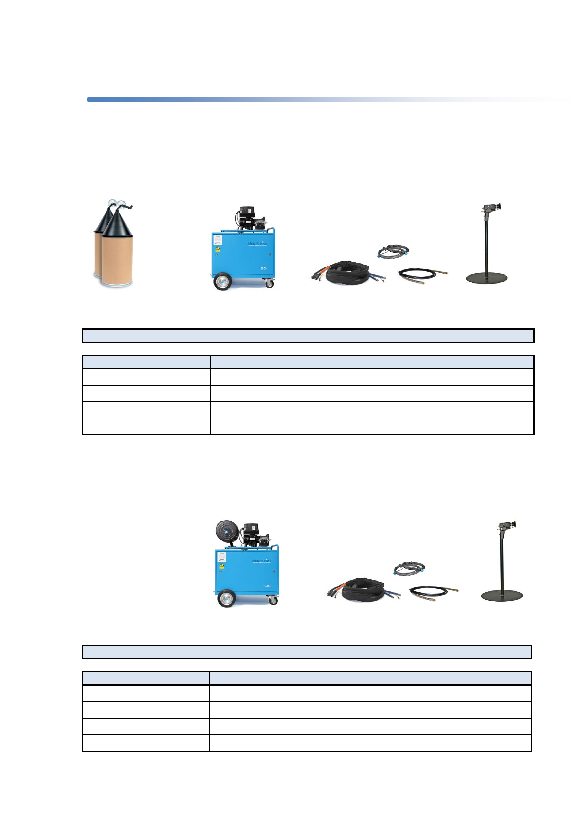
Standard Configuration –Push/Pull with wire in Drums
Most commonly used for in-house anti-corrosion applications where drums can easily be handled.
Standard Configuration –Push/Pull with wire on MIG reels
Most commonly used for on-site anti-corrosion applications where loading of the smaller MIG reels is
more feasible than using drum material.
STANDARD DRUM SYSTEM PART NUMBERS
PART NO
DESCRIPTION
ARC150-2310D
ARC150 System, 2.3mm, 10m supplies, drum dispense
ARC150-2320D
ARC150 System, 2.3mm, 20m supplies, drum dispense
ARC150-2510D
ARC150 System, 2.5mm, 10m supplies, drum dispense
ARC150-2520D
ARC150 System, 2.5mm, 20m supplies, drum dispense
STANDARD MIG SYSTEM PART NUMBERS
PART NO
DESCRIPTION
ARC150-2310M
ARC150 System, 2.3mm, 10m supplies, MIG dispense
ARC150-2320M
ARC150 System, 2.3mm, 20m supplies, MIG dispense
ARC150-2510M
ARC150 System, 2.5mm, 10m supplies, MIG dispense
ARC150-2520M
ARC150 System, 2.5mm, 20m supplies, MIG dispense
Energiser and push/pull
drive unit
Energiser and push/pull
drive unit
Pistol
Pistol
10m / 20m supplies from wire
drive to pistol
10m / 20m supplies from wire
drive to pistol
3m max.
Wire in drums or
coils
Page 16 of 48
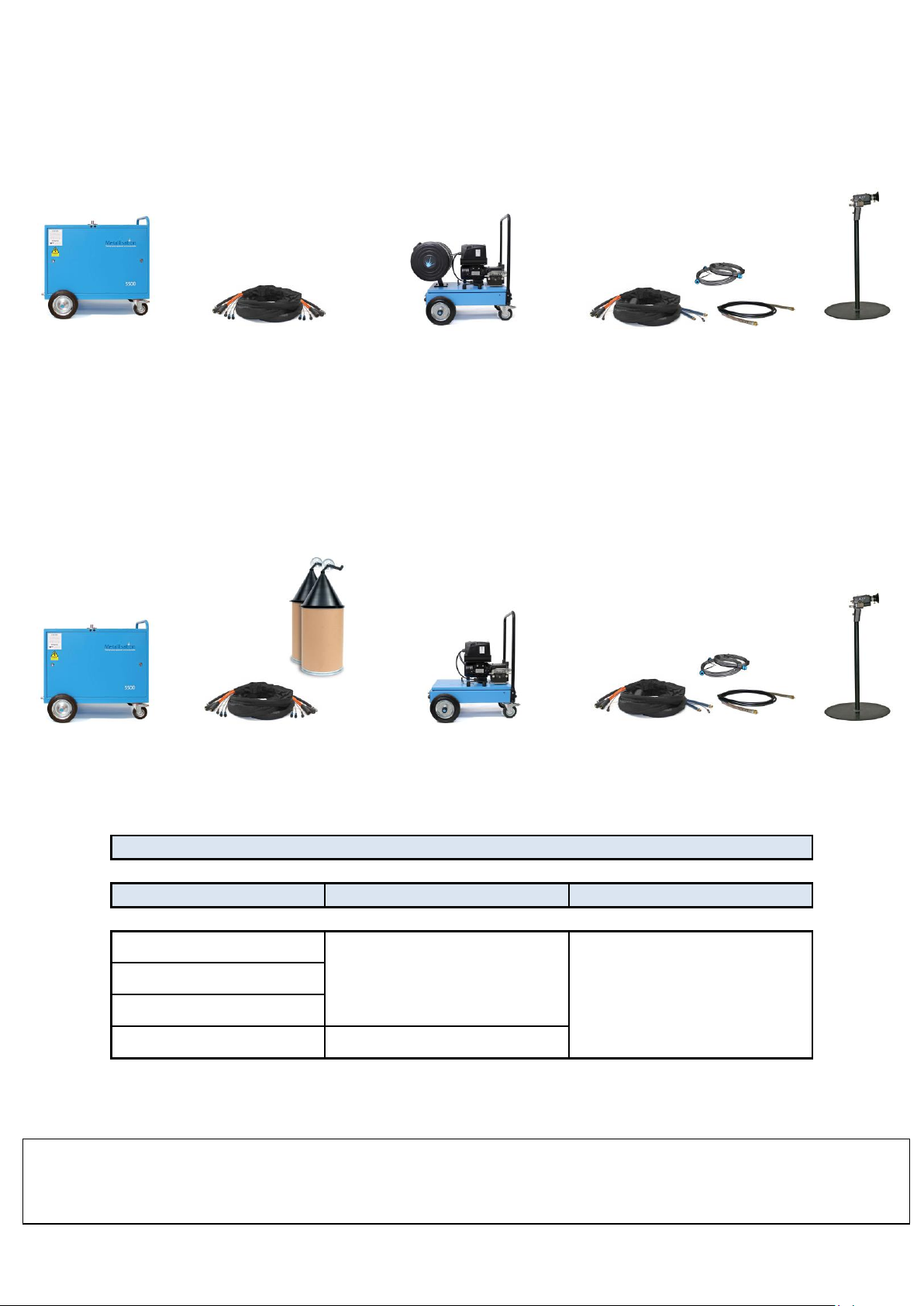
Extended Configuration –Push/Pull with wire on MIG reels
Most commonly used in hard to reach areas such as boilers/vessels where access for the energiser is
limited. Hardboard reel variant can also be offered on the trolley.
Extended Configuration –Push/Pull with wire in Drums
Most commonly used for very long access applications where there is a benefit to remotely site the
energiser away from the spraying area and maintain the benefit of having wire in drums.
NB: Maximum total supplies length is 50M. This can be a combination of 30 + 20 or 40 + 10.
TYPICAL EXTENDED SUPPLIES CONFIGURATION
EXTENDED SUPPLIES
PISTOL SUPPLIES
TOTAL MAX
10M
10/20M
50M
20M
30M
40M
10M
Energiser
Pistol
Extension
Supplies
Pistol
Energiser
Wire in drums
3m max. (2m
std) wire to drive
Extension Supplies
Push/pull drive unit and MIG
reels on power extension
trolley with quick release
connections
Push/pull drive unit on power
extension trolley with quick
release connections
Supplies from wire drive to
pistol
Supplies from wire drive to
pistol
Also available is the Push/Pull with wire on hardboard reels configuration –most commonly used for on-site anti-corrosion
applications where loading of Hardboard reels is more feasible than using drum or MIG material. Hardboard reels are
common in some markets and allow a larger amount of wire to be held on the reel than traditional MIG reels.

Page 17 of 48
SECTION 3
OPERATING THE EQUIPMENT
3.1 Connecting the System
3.2 Connecting using a Powered Extension Trolley
3.3 Preparing to Spray
3.4 Spraying
3.5 Shutting Down
3.6 Remote Pendant
3.7Using Optional Arc Extension
3.8Closed Loop and Open Loop Modes
Page 18 of 48
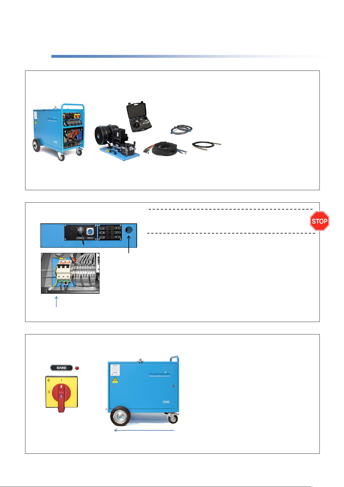
3.1 Connecting the System
1
The Energiser should be connected to an appropriate 3 phase power
supply by a competent qualified electrician in accordance with the
following recommendations:
Position the Energiser to allow unrestricted airflow into / out of the unit and
connect to a mains isolator fuse box ensuring each phase carries suitable
fuses.
Remove the top panel and connect a suitable Power Cable to terminals 1, 2,
3 and Earth.
Check that the input voltage is correct for the unit (Refer to Energiser
Maintenance Manual).
Connect suitable size hose to the air supply. It is strongly recommended that
a filter unit be installed at the mains outlet point. A capacity of 1.5m³ /min @
5 bar (53cfm @ 72.5 psi) is usually adequate.
2
3
Remove any packing materials and ensure that all items are present and the equipment has suffered no damage whilst in transit
(see conditions of sale). NB: if using long supplies with a powered extension trolley also refer to Section 3.2.
A. S500-PLC Energiser.
B. Drive Unit Assembly.
C. Power Cable / Air Hose Assembly.
D. Wire Feed Conduits.
E. Flexible Drive Cable.
F. ARC150 Pistol and Tool Case.
Switch on Power Supply and turn the Mains
Switch on.
Cooling Airflow should pass from front to
back. If air passes from the back to the front
of the Energiser, the fan is running in
reverse.
If this is allowed to continue damage to the
Energiser may occur. Isolate the Power
Supply and reverse two phases of the
input 3 phase.
Once airflow is passing through correctly,
turn the Mains Switch off and refit all panels.
AIRFLOW
Rear of Energiser
A
B
F
E
C
D
Power Terminals
Feed Power
Cable through
opening using a
suitable Gland
Page 19 of 48
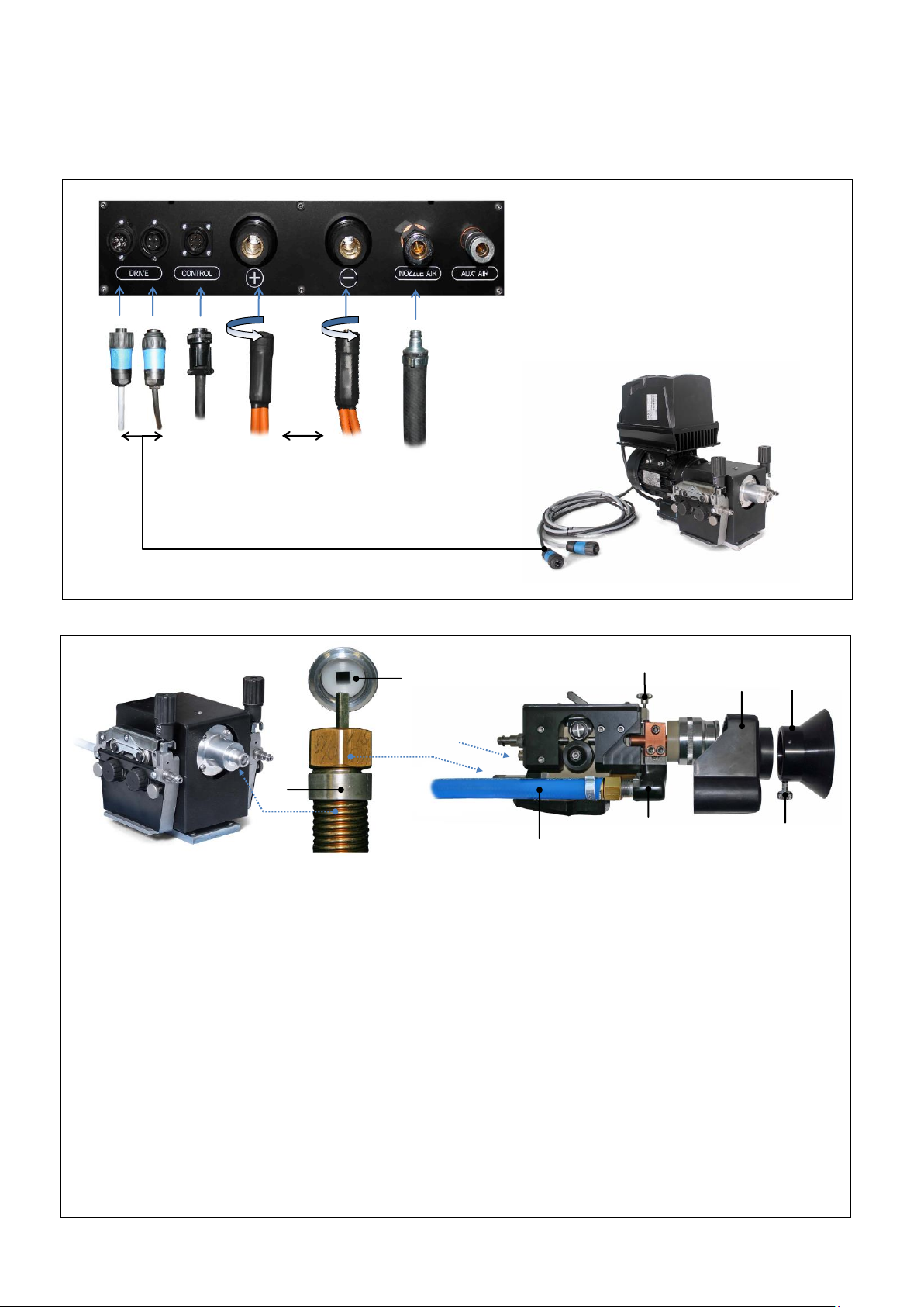
Connecting the System continued…
1. Loosen the Pointed Shroud Screw (A) and remove the Shroud (B). Unscrew the Thumb Screw (C) and remove the Hood (D)
from the Pistol.
2. Take one end of the Flexible Drive Cable (E) and carefully position the squared end of the inner into the rear of the Pistol
coupling (F). Apply some grease to the thread on the drive connector and screw home the drive connector ring whilst holding the
Flexible Drive in place. Lightly tighten with the provided spanner. Connect the other end of the Flexible Drive Cable to the DUA
Wire Feed Unit applying grease to the Drive Connector as before.
3. Fit the 2 Cooled Conductors (H) to the Terminal Blocks (G) and firmly tighten. Use one spanner to hold the Terminal Block whilst
tightening the conductor with another to prevent damage to the Terminal Blocks. This joint will carry up to 500 amperes so
ensure they are securely tightened and check periodically.
4. Replace the Hood (D) and Shroud (B).
5. Connect the Control Cable from the supplies pack to the rear of the Pistol (I).
Connect the Control Cables from the DUA Wire Feed Unit (D) to the Energiser.
Ensure that power to the Energiser is isolated.
Connect the Supplies Pack, comprising Power
Cables (A), Motor Drive Cable (B) and Nozzle
Air Hose (C) from the Manifold to the
appropriate connections on the front of the
Energiser.
Polarity of Power Terminals is unimportant
unless spraying pseudo alloys (2 different
materials) - twist power terminals clockwise
firmly to lock.
4
5
‘CLICK’
D
A
A
B
C
D
G
H
C
B
E
F
I

Page 20 of 48
3.2 Connecting using a Powered Extension Trolley
Using a Powered Extension Trolley allows the Energiser to be sited further away from the
spray job whilst still maintaining the power, air and control couplings quick release feature.
PART NO.
DESCRIPTION
ARC150-PET
ARC150 powered extension trolley for ARC150 system
FRONT
BACK
This manual suits for next models
7
Table of contents
Other Metallisation Paint Sprayer manuals


