Metallisation MK 73 Guide

Page 1of 64
ssue: 21/11-11

Page 2of 64
Issue: 07-10-2013
This operating manual must be read and understood before any
attempt is made to operate the equipment described herein. In
particular, refer to the Safety Warnings / Risk Assessments in
Section 1.
Under no circumstances should any modifications be made to
the equipment without prior written approval from Metallisation.

Page 3of 64
SPECIFICATIONS
The Metallisation MK73 is an Oxygen –Propane fuelled flame spray system typically used for
the application of anti-corrosion coatings. The following specifications are for a standard Pistol
system with 1/4" hoses.
Weight - Complete, excluding supply hoses 2.27Kg (5lb)
Pistol Dimensions
LENGTH
HEIGHT
WIDTH
25.7cm (10 1/8”)
28.6cm (11 1/4”)
9.5cm (3 3/4”)
Typical Performance Figures
MATERIAL
WIRE SIZE**
THROUGH -PUT
(kgs/Hr)
THROUGH -PUT
(lbs/Hr)
01E Aluminium
3/16” Fast
3/16”
1/8”
2mm
12.5
8.0
3.6
2.3
27.00
16.5
8.0
5.0
02E Zinc
3/16” Fast
3/16”
1/8”
2mm
50.0
32.0
16.0
8.2
110.0
70.0
35.0
18.0
07E/08E/09E Tin/Zinc
1/8”
2mm
21.3
9.1
47.0
20.0
05E, 10E & 15E Copper &
Bronzes
1/8”
2mm
5.9
4.1
13.0
9.0
30E, 35E, 45E, 55E, 57E
60E, 65E, 80E & 85E
Steels & Nichrome
1/8”
2mm
4.3
2.7
9.0
6.0
21E Zinc/Aluminium 85/15
3/16” Fast
3/16”
1/8”
2mm
38.0
25.0
12.5
7.5
84.0
55.0
27.0
16.0
06E Nickel
1/8”
3.6
8.0
** Stop/start unless otherwise specified in bold.
Services Required
The following air, gas and oxygen pressure and consumption figures cover the full range of
possible nozzle assemblies:
Compressed Air
Gases
Oxygen
Propane
30 cfm @ 80psi
50m³/hr @ 5.5 bar
48-280 cfh @ 22-70 psi
1.36-7.9 m³/hr @ 1.5-4.8 bar
22-56 cfh @ 25-60 psi
0.62-1.59m³/hr @ 1.7-4.1 bar

Page 4of 64
CONTENTS
SECTION 2
SAFETY PRECAUTIONS & RISK ASSESSMENTS................................................................................6
1.1 Safety Precautions......................................................................................................................................7
1.1.1 Equipment Dos and Don’ts.......................................................................................................................7
1.1.2 Leak Test Procedures..............................................................................................................................8
1.1.3 Flashback.................................................................................................................................................9
1.2 Risk Assessment......................................................................................................................................10
1.3 Key Hazards.............................................................................................................................................11
1.3.1 Noise......................................................................................................................................................11
1.3.2 Flame.....................................................................................................................................................11
1.3.3 Particles.................................................................................................................................................11
1.3.4 Mechanical Hazards...............................................................................................................................12
1.3.5 Fume & Dust..........................................................................................................................................12
1.3.6 Summary................................................................................................................................................14
SECTION 2
THE EQUIPMENT ..................................................................................................................................15
2.1 Introduction to the MK73...........................................................................................................................16
2.2 Breakdown................................................................................................................................................17
2.2.1 The Pistol...............................................................................................................................................18
2.2.2 Flowmeter..............................................................................................................................................19
2.2.3 Air Filtration & Regulation Unit (ARF).....................................................................................................19
2.2.4 Pressure Regulators & Flashback Arrestors...........................................................................................19
2.2.5 Freestanding Flamespray Control Board................................................................................................19
2.2.6 Supplies Packages.................................................................................................................................20
SECTION 3
OPERATING THE EQUIPMENT ............................................................................................................22
3.1 Preparing the System ...............................................................................................................................23
3.2 Starting to Spray.......................................................................................................................................23
3.3 Spraying ...................................................................................................................................................25
3.4 Extinguishing the Pistol.............................................................................................................................26
3.5 Emergency Shut-Off Valve........................................................................................................................26
SECTION 4
MAINTENANCE & REPAIR....................................................................................................................27
4.1 Recommended Spares .............................................................................................................................28
4.2 Routine Maintenance................................................................................................................................28
4.3 Disconnecting the Pistol............................................................................................................................29
4.4 The Nozzle Assembly...............................................................................................................................30
4.4.1 Removal & Dismantling..........................................................................................................................30
4.4.2 Nozzle Re-Assembly..............................................................................................................................31

Page 5of 64
4.5 The Gas Head & Main Valve.....................................................................................................................32
4.5.1 Removal & Dismantling..........................................................................................................................32
4.5.2 Gas Head & Valve Re-Assembly............................................................................................................33
4.6 The Drive Box...........................................................................................................................................34
4.6.1 Dismantling the Wire Drive Assembly ....................................................................................................35
4.6.2 Dismantling the Air Shield Valve ............................................................................................................36
4.6.3 Dismantling the Speed Control...............................................................................................................37
4.6.4 Re-Assembling the Speed Control .........................................................................................................37
4.6.5 Re-Assembling the Air Shield Valve.......................................................................................................38
4.5.6 Re-Assembling the Wire Feed Drive......................................................................................................38
4.7 The Drive Motor........................................................................................................................................41
4.7.1 Dismantling the Drive Motor...................................................................................................................41
4.7.2 Re-Assembling the Drive Motor..............................................................................................................41
4.8 Feed Roller Tension..................................................................................................................................42
4.8.1 Checking Feed Roller Tension ...............................................................................................................42
4.8.2 Adjusting Feed Roller Tension ...............................................................................................................42
SECTION 5
FAULT FINDING.....................................................................................................................................43
5.1 Troubleshooting........................................................................................................................................44
5.1.2 Flowmeter Troubleshooting:...................................................................................................................46
SECTION 6
WIRE DISPENSING................................................................................................................................48
6.1 Wire Swift .................................................................................................................................................49
6.1.1 Operating Instructions............................................................................................................................49
6.1.2 Wire Straightener...................................................................................................................................50
SECTION 7
ILLUSTRATED PARTS LIST .................................................................................................................51
7.1 Gas Head & Spreader Nozzle...................................................................................................................52
7.2 Diaphragm Valve ......................................................................................................................................54
7.3 Power Unit / Drive Motor...........................................................................................................................54
7.4 Wire Drive Unit & Feed Control.................................................................................................................56
SECTION 8
INFORMATION TABLES .......................................................................................................................58
8.1 Flowmeter Settings...................................................................................................................................59
8.2 Nozzle Selection Chart..............................................................................................................................60

Page 6of 64
SECTION 1
SAFETY PRECAUTIONS & RISK ASSESSMENTS
1.1 Safety Precautions
1.1.1 Equipment Dos & Don’ts
1.1.2 Leak Test Procedure
1.1.3 Flashback
1.2 Risk Assessments
1.3 Key Hazards
1.3.1 Noise
1.3.2 Flame
1.3.3 Particles
1.3.4 Mechanical Hazards
1.3.5 Fume & Dust
1.3.6 Summary

Page 7of 64
1.1 Safety Precautions
Provided that the equipment is properly set up, regularly maintained and used correctly, metal
spraying does not present any great danger. However, like most industrial processes, misuse
and careless practices can create hazards for personnel and damage to the equipment.
The equipment detailed in this manual will produce levels of noise and dust that require safety
measures to be taken by personnel using the equipment. It uses pressurized and flammable
gases. Careful consideration should be taken when positioning this equipment.
It is the responsibility of the user to ensure that all appropriate measures are in place for safe
operation, before the equipment is used. Metallisation will be pleased to assist and advise as
appropriate.
1.1.1 Equipment Dos and Don’ts
Check all hoses regularly. Damaged hoses must be replaced immediately.
Ensure that all hose connections are properly tightened and do not leak.
Ensure that proper extraction is available and is turned on before the gas supplies
are tuned on and turned off after the gas supplies are turned off.
NEVER point the pistol towards other personnel or combustible material.
NEVER spray onto hoses, regulators or flowmeters.
NEVER operate the pistol without using ear defenders and the appropriate eye protection.
NEVER apply grease to any thread or connection which is to carry oxygen.
NEVER operate the pistol without using regulators fitted with flashback arrestors.
NEVER release gases into an un-extracted area.

Page 8of 64
1.1.2 Leak Test Procedures
Leak Test Procedure - to be carried out before the pistol is used:
Make sure all the hoses are connected correctly and gauges are in good working
order.
Fit the leak test nozzle 1260 on to the pistol.
Switch on extraction.
Open gas cylinder valves.
Open the regulators to the standard operating pressures.
Open fully the gas valve on the pistol.
Set the regulators to the required working pressures.
Close the cylinder valves and screw out the regulators.
Watch the cylinder pressure gauges on the oxygen and fuel gas for approximately 5
minutes.
If the cylinder input pressure gauge drops then there is a leak between the cylinder
and the regulator. Use a leak detection spray or liquid to identify, then rectify leak
before using the pistol.
If the cylinder output pressure gauge drops then there is a leak between the regulator
and the nozzle. Use a leak detection spray or liquid to identify, then rectify leak before
using the pistol.
If no movement of the pressure gauges is seen then the system has no identifiable
leak and is safe to use.
To release pressure, release the fittings on the exit of the flashback arrestors. Then
re-tighten.
Remove the leak test nozzle and replace with the standard nozzle assembly
Alternatively:
Carry out first 7 points, then:
Using a proprietary leak detection spray or liquid check all hose and accessory
connections and pistol valve assembly mating faces.
If a leak is detected however small it must be rectified before the system is put into
operation.
Turn off the gases and close the pistol valve. Carefully undo the gas fittings to release
gas. Ensure fittings are re-tightened.
Results:
Cylinder Input Pressure Gauge Drops –There is a leak between the cylinder and the regulator
Cylinder Output Pressure Gauge Drops –There is a leak between the regulator and the pistol.

Page 9of 64
Under these circumstances, use a leak detection spray or liquid to identify, then rectify the
leak before using the Pistol. If there is no movement of pressure gauges, then there is no
identifiable leak and the pistol is safe to use.
NB: Leak Test Information is based on the assumption that all pressure gauges are in
good working order, with any visible defects having already been rectified e.g.
damaged hoses, broken flowmeters etc…
1.1.3 Flashback
Poorly maintained equipment may on occasion produce flashbacks If hose protection and
flashback arrestors are fitted, the risk of flames reaching the fuel gas and oxygen supplies is
virtually eliminated.
However, flashback, particularly if sustained, can seriously damage the nozzle assembly.
Therefore, if flashback occurs, the following procedure should always be carried out:
1) Immediately close the Pistol valve.
2) Shut off the Oxygen Supply Valve.
3) Shut off the Fuel Gas Supply Valve.
4) If fitted, operate the Safety Shut-Off Handle on the flowmeter.
5) Re-open the Pistol Valve and allow air to flush the nozzle parts for approximately 30
seconds.
6) Restart the system as identified in Section 3.2
7) If on re-lighting the flashback is repeated, shut off as above and ascertain the cause.

Page 10 of 64
1.2 Risk Assessment
Prior to commencing work with Thermal Spray equipment, a Risk Assessment should be
carried out on the equipment and the way in which that equipment is to be used.
The Risk Assessment should identify the hazards associated with the work and also the
control measures required. This will either eliminate the risk, or reduce it to an acceptable
level to prevent ill health or injury to the persons carrying out, or who could be affected by the
work.
The results of the Risk Assessment and the control measures necessary should be made
known to the persons carrying out, or those affected by the work.
Some control measures are better able to produce the desired result than others.
The safety precedence sequence shows the order of effectiveness of measures.
Hazard Elimination
Use of alternative work methods, design improvements or change of process.
Substitution
Replacement of material/substance with another of less risk.
Use of Barriers
Isolation or segregation.
Use of Documented Procedure
Limiting exposure times, dilution of exposure. Safe systems of work that depend on human
response.
Use of Warning Signs
Signs, instructions, labels that depend on human response.
Use of Personal Protective Equipment (PPE)
Depends on human response, used as a sole measure only when all other options have been
exhausted. PPE is the last resort.
It is the responsibility of the user of the equipment to ensure that all appropriate control
measures identified in the Risk Assessment are in place before using the equipment
To assist you in carrying out you Risk Assessment we have identified the Key Hazards in the
operation of Thermal Spray Equipment and this information can be found in Section 1.3.
In this section the key hazards associated with Thermal Spraying are described. It includes a
brief description of the hazards and their possible consequences. In any Risk Assessment for
a Thermal Spray Process, a consideration of all relevant hazards will need to be included.
Ancillary activities that are likely to be undertaken, such as grinding, grit blasting, solvent
cleaning, machining etc., are not included in this section.

Page 11 of 64
1.3 Key Hazards
In this section the key hazards associated with Thermal Spraying are described. It
includes a brief description of the hazards and their possible consequences. In
any Risk Assessment for a Thermal Spray Process, a consideration of all relevant
hazards will need to be included. Ancillary activities that are likely to be undertaken,
such as grinding, grit blasting, solvent cleaning, machining etc., are not included
in this section.
1.3.1 Noise
The two main factors that make noise in the workplace harmful are the loudness of the noise
and the length of time a person is exposed to it each day. Noise destroys the delicate nerve
cells in the inner ear that transmit sound messages to the brain. The nerve cells are replaced
by scar tissue that does not respond to sound. This damage occurs painlessly and very slowly,
but is permanent. There is currently no cure for noise-induced hearing loss, It is permanent
and cannot be helped by hearing aids. All spraying processes are noisy and may generate
noise levels in excess of the first action level. Users of thermal spray equipment are
responsible for conducting their own noise assessments, which must be based on the
exposure of the persons in the workplace, and of which a noise survey is only part.
Key Hazards: Stress, difficulty in communication, long term hearing loss, Tinnitus
NEVER operate the system without adequate hearing protection.
ALWAYS ensure that ALL personnel likely to be exposed are adequately protected, including
those not directly involved in the process.
1.3.2 Flame
The flame spray process produces a flame that presents a burn risk. Also, the work
pieces will get hot, particularly when higher melting point materials have been sprayed.
Key Hazards: Burns
1.3.3 Particles
Always wear eye protectors when operating, or watching the flame spray operation.
Inspect the eye protectors frequently. Lenses and over plates, which are scratched, pitted or
damaged, can impair vision and seriously reduce protection. All personnel in eye hazard areas
should wear protective eyewear. This includes employees, visitors, researchers, contractors,
or others passing through an identified eye hazard area. To provide protection for these
personnel, a sufficient quantity of goggles and/or plastic eye protectors should be available. If
personnel wear personal glasses, eye protectors suitable to wear over them should be
provided.
Key Hazards: Particles in eye

Page 12 of 64
1.3.4 Mechanical Hazards
If equipment has been installed to manipulate the component and/or spray gun, it is
important that it is designed to protect the operator from mechanical hazards. It is possible for
the operator to be struck by a moving table or manipulator, to be crushed against the wall of
the booth, or to become entangled in rotating machinery. Serious injury could occur. Trailing
cables and other obstructions present a tripping hazard, and because of the relatively confined
area of a spray booth, and the close proximity to machinery, the consequences may be
serious.
Key Hazards: Entanglement, being struck by machinery, trips and falls.
1.3.5 Fume & Dust
Powdered metals, particularly titanium, aluminium and magnesium give rise to a fire
and explosion risk, depending on the circumstances. Powdered materials can collect in
ducting, on filters, and around the spray booth. If these accumulations are heavy, and they are
disturbed, they can be ignited. An explosion may result from the ignition of a dust cloud,
inside, or outside the equipment. A fire may follow from an explosion and its fireball, or may
result from self-ignition of layers of accumulated dust on hot surfaces, including some
electrical equipment.
Many of the materials that are routinely sprayed have the potential to be hazardous to health
due to their intrinsic properties. Even the least toxic materials, if present in the air in sufficient
quantities, can be hazardous to health. Dust produced by the process produce airborne
particulate matter, in size ranges that can be inhaled. Both inhalable and respirable matter
may be produced. Respirable particles are more dangerous because they can be breathed
deeply into the lungs. The user must therefore identify the hazards, assess the risks, and
prevent or, where not reasonably practicable, adequately control them. The assessment must
take into account all occasions where exposure may occur –which include spraying, cleaning,
disposal and maintenance.
Several commonly sprayed substances are subject to statutory exposure limits. The
assessment must take into account these exposure limits. When a substance or preparation
has an occupational exposure standard, control of exposure is adequate if levels are
maintained below that standard. The information that follows includes the most commonly
sprayed materials. However, other materials may also be toxic. It is essential that users
consult the MSDS (Material Safety Data Sheets) that arrive with their consumables
(manufacturers must supply these), so that they can take into account the health effects, any
exposure limits, and any properties such as explosion hazard, when conducting their risk
assessments.
Key Hazards: Fire & explosion, toxic effects by inhalation, toxic effects by skin contact.
The information that follows highlights the most commonly sprayed materials and their
potential effects.
= Highly Flammable
= May react with water to form hydrogen

Page 13 of 64
Aluminium
Long term inhalation of aluminium powder or aluminium oxide may cause scarring of the
lungs. Aluminium powder can form explosive mixtures with air.
Chromium
Prolonged exposure to chromium metal dust may give rise to lung fibrosis. It is highly toxic.
Chromium oxide and chrome carbide feedstock are both chromium (III), the less toxic form of
chromium. However spraying may convert chromium (III) compounds to chromium (IV)
compounds, which are suspected human carcinogens. Exposure to chromium (IV)
compounds must be kept as far below the maximum exposure limit (MEL) as is reasonably
practicable.
Cobalt
Cobalt is moderately toxic. It may cause sensitisation by inhalation and skin contact, resulting
in occupational asthma and allergis dermatitis. Exposure must be kept as far below the
maximum exposure limit (MEL) as is reasonably practicable.
Copper
Copper fume may give rise to metal fume fever. Inhalation may cause muscle weakness and
headache. Some compounds of copper are highly toxic and may cause long term effects.
Iron
Inhalation of iron oxides over a long period may cause scarring of the lungs without
physiological symptoms.
Molybdenum
Occupational ill-health from exposure to molybdenum is unlikely.
Nickel
Nickel is harmful. Repeated skin contact may cause allergis contact dermatitis. It is a suspect
human carcinogen, and exposure must be kept as far below the maximum exposure limit
(MEL) as is reasonably practicable.
Tin
Tin powder may cause irritation. Inhalation over a long period may cause scarring of the lungs
without physiological symptoms.
Titanium
Occupational ill-health from exposure to titanium is unlikely.
Zinc
Zinc can cause metal fume fever, but is otherwise only moderately toxic.
NOTE: In certain concentrations, a mixture of aluminium dust and iron oxide (rust) can
cause a thermitic reaction, resulting in a spontaneous combustion. This is very rare but
efforts should be made to minimise cross contamination of aluminium dust and iron oxide.
Page 14 of 64
1.3.6 Summary
Below is an approximate rating of the hazards in typical circumstances while using the MK73
Flame Spray System. It must be stressed that the hazard ratings may change in individual
circumstances. An example of this would be the rating for toxic consumables. This would
relate directly to the consumable in use.
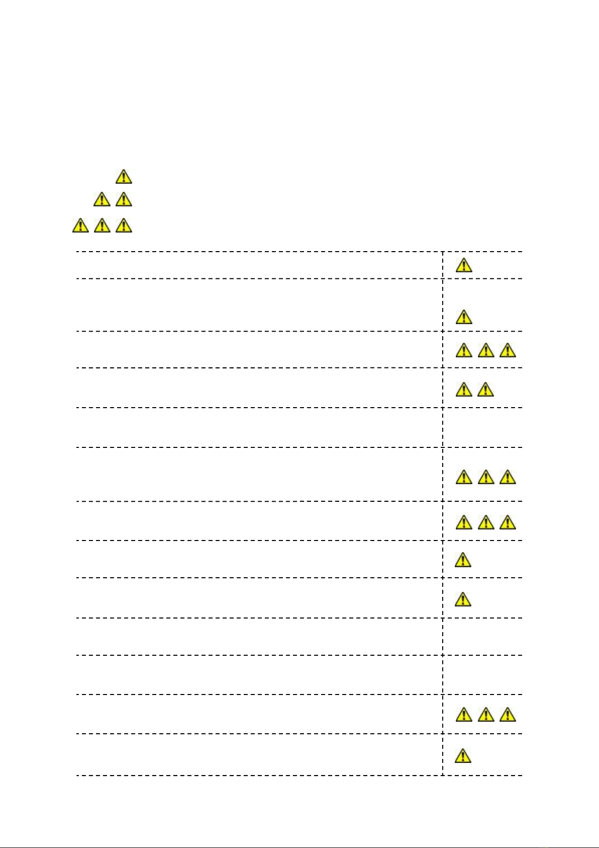
Compressed Gases
Highly Flammable / Extremely flammable gases. Hydrogen,
Propane, Acetylene, LPG and/or Oxygen (fire and explosion risk)
Asphyxiant Gases
Noise
UV Radiation
Fine Dusts, fume and
powders (explosion risk)
Potentially toxic consumables
Water borne disease (water curtain fitted)
Mechanical Hazard (automated equipment)
Electric Shock
Cryogenic Gases
Burns
Stab Risk
Lower level of hazard
Medium level of hazard
Very high level of hazard

Page 15 of 64
SECTION 2
THE EQUIPMENT
2.1 Introduction to the MK73
2.2 Breakdown
2.2.1 The Pistol
2.2.2 Flowmeters
2.2.3 Air Filtration & Regulation Unit
2.2.4 Pressure Regulators & Flashback Arrestors
2.2.5 Freestanding Flamespray Control Board
2.2.6 Supplies Packages

Page 16 of 64
2.1 Introduction to the MK73
This hand held flame spray pistol is designed to produce coatings from wires of
all common sizes, and is able to accept wire sizes from 1.5mm to 3/16”.
This pistol is primarily recommended for anti-corrosion and tool making
applications, electronics and other instances where the main coatings produced are
from the lower melting point materials e.g.: Zinc, Aluminium and other similar alloys. It
is also suitable for use with some of the Engineering Wires e.g. Steels and Bronzes.
The MK 73 boasts the following features:
A rugged construction, which is designed to meet all the requirements of the practical
metal sprayer.
A Propane fuelled gas head valve, spraying anti-corrosion or similar coatings at very
high speed.
A high torque positive displacement air motor which feeds the wire, doubling as the
pistol handle.
A pressure compensating valve built into the exhaust port of the motor which provides
variable speed control, to cater for materials with different melting points.
A nozzle system that is designed to ensure true axial alignment of the component
parts, all mating faces being provided with push fit gas seals for simple leak proof
assembly. Excellent flame stability and easy lighting is afforded by the pneumatic self-
adjusting air nipple.**An adjustable spreader providing a wider spray pattern is
available as standard on 3/16” and 1/8” systems, which can be turned on/off during
spraying.
A multi diaphragm main valve, supplying air, fuel gas and oxygen to the gas head.
The sealing diaphragms are operated collectively by a pre-set cam. Internal leakage
between fuel gas and oxygen ports is impossible and the sequence in which the
various gases are released to the gas head cannot become out of phase.
An easily operated pilot valve, which allows the pistol to be lit by numerous methods,
i.e.: spark gun, cigarette lighter etc…
Fingertip operation of a trigger valve, located on the motor inlet. This ensures
instantaneous stop/start control of the wire feed.
An exclusive patented feature of the stop/start system is the provision of an air heat
shield at the nozzle, which automatically prevents the wire melting back and becoming
welded to the nozzle when the wire feed is stopped.** **This facility is not available in
‘continuous spray mode’.

Page 17 of 64
2.2 Breakdown
Here are the typical system configurations for the Metallisation MK73 Flame Spray
system:
Individual Components:
NB: Cylinders not supplied
NOTE: Also Available is the Metallisation Extension Nozzle, equipment specification available
upon request
The Pistol
(Section 2.2.1)
Air Filtration &
Regulation Unit
(Section 2.2.3)
Pressure Regulators
& Flashback Arrestors
(Section 2.2.4)
Maximum 20m from cylinders
to pistol with 1/4” ‘short’ hoses
1
3
5
1
2, 3 & 4
Flowmeter
(Section 2.2.2)
FlowMeter Board
(Section 2.2.5)
2
4
5
Maximum 40m from cylinders to
pistol with 3/8” ‘long’ hoses
Supplies Pack
(Section 2.2.6)
6
6
3m standard
6m standard
Page 18 of 64
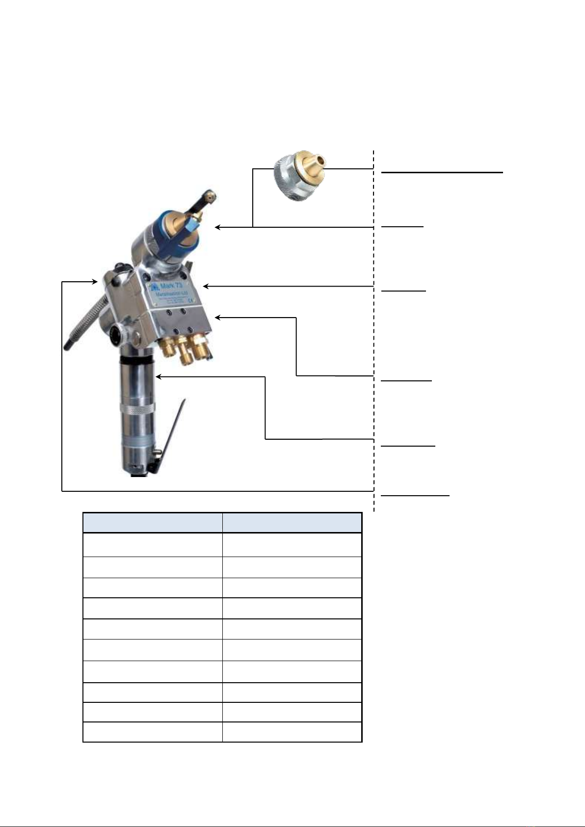
2.2.1 The Pistol
Pistols vary dependant on the wire size that is to be sprayed. The Pistol shown is for a
standard 3/16” System. The table below this illustration gives the variant pistol part numbers
for the relevant wire size that is used:
Pistol Part No:
Wire Type
GAS73-1.6MM
1.6mm
GAS73-2MM
2mm
GAS73-2.3MM
2.3mm
GAS73-3MM
3mm
GAS73-1/8
1/8” (3.17mm)
GAS73-4MM
4mm
GAS73-3/16
3/16” (4.76mm)
GAS73-3/16”F
3/16” (fast)
GAS73L-1/8
1/8” (Long Supplies)
GAS73L-3/16
3/16” (Long Supplies)
Spreader
Directs air jets at the spray
stream to give a wider spray
pattern.
Nozzle (Without Spreader)
Accurately profiled and sleeved
with stainless steel insert.
Gas Head
Fuel gas, oxygen and
compressed air are conveyed
through the gas head from the
main valve to the nozzle
assembly.
Main Valve
A diaphragm valve assembly
which controls the gases to the
gas head.
Drive Motor
High torque positive
displacement air motor.
Wire Feed Unit
Self centering feed roller assembly
eliminating wire misalignment
and scuffing.
NOTE: The Illustration above
shows the Optional Spreader. The
Spreader is included on 1/8” and
3/16” systems as standard.

Page 19 of 64
2.2.2 Flowmeter
Flowmeters indicate the relative flows of fuel gas and oxygen, and allow the
correct spraying parameters essential for high efficiency and top quality
coatings, to be achieved more easily and reliably than when using pressure
regulators alone. They are invaluable fault finding aids and can save unwanted
downtime when used in this capacity.
These instruments are mounted on a sturdy steel back plate which allows the
unit to be wall mounted. Left hand threads are standard on fuel gas fittings so
that gas and oxygen hoses cannot be incorrectly fitted. Various Hose
configurations can be supplied.
2.2.3 Air Filtration & Regulation Unit (ARF)
When connected to a suitable air supply this unit provides filtered air to
the nozzle system, and lubricated filtered air to the pistol power unit.
Nozzle Air Pressure is adjustable using the integral regulator.
A sight glass at the top of the lubricator, makes it simple to observe the
rate of oil feed to the motor. The oil feed adjustment on the top of the
lubricator, controls the oil feed rate. Only high quality light lubricating oil
such as Metallisation Lubricating Oil should be used.
2.2.4 Pressure Regulators & Flashback Arrestors
The pistol should be used with Metallisation high flow two stage
regulators, which are supplied with the correct fittings for connection to
the MK73.
It is imperative that these regulators are fitted with Flashback Arrestors
which will protect the Fuel Gas and Oxygen supplies in the event of a
flashback (a flame travelling back up the hose).
Metallisation Flashback Arrestors are recommended. All pressure and flowmeter settings
given in this manual are correct for this type only.
When using long regulator to flowmeter hose supplies 20m +, on gas systems the Inline
flashback arrestors 21125 oxygen arrestor and 21124 propane / acetylene arrestor MUST be
fitted to the flowmeters.
2.2.5 Freestanding Flamespray Control Board
For some installations a Panel Mount Oxygen Regulator can be fitted
to the panel (A) along with secondary flash back arrestors and a
emergency shut down valve assembly (B).
The Local oxygen regulator allows for precise flame adjustment where
the supply cylinders are not close by the spraying area.
The additional flashback arrestors are fitted to add additional protection when using very long
3/8” hoses. The emergency shutdown valve assembly is fitted to enable a complete gas shut
off to the pistol in the event of a malfunction, i.e. a flashback.

Page 20 of 64
2.2.6 Supplies Packages
Metallisation can supply standard and non-standard hose sizes, to suit the appropriate
application. Listed below are the part numbers for ‘short’ hose configurations (1/4” hoses):
Supplies from cylinders to flowmeters
Supplies from flowmeters to Pistol
SUP73-FLOW 3M
3m supplies package
Consisting: 21140 Propane Hose
21223 Oxygen Hose
SUP73-PISTOL 6M
6m supplies package
Consisting: 21501 Propane Hose
21502 Oxygen Hose
21503 Nozzle Air Hose
21504 Motor Air Hose
SUP73-FLOW 3M
3m supplies package
Consisting: 21140 Propane Hose
21223 Oxygen Hose
SUP73-PISTOL 10M
10m supplies package
Consisting: 21501/10 Propane Hose
21502/10 Oxygen Hose
21503/10 Nozzle Air Hose
21504/10 Motor Air Hose
SUP73-PISTOL 10M
10m supplies package
Consisting: 21501/10 Propane Hose
21502/10 Oxygen Hose
21503/10 Nozzle Air Hose
21504/10 Motor Air Hose
SUP73-FLOW 10M
10m supplies package
Consisting: 21140/10 Propane Hose
21223/10 Oxygen Hose
Propane Hose
Oxygen Hose
Propane Hose
Oxygen Hose
Nozzle Air Hose
Motor Air Hose
Part Number
Part Number
Part Number
Other manuals for MK 73
1
Table of contents
Other Metallisation Paint Sprayer manuals


Popular Paint Sprayer manuals by other brands


Kränzle
Kränzle FoamBoy 100 operating instructions

WALTHER PILOT
WALTHER PILOT PILOT II operating instructions

Smith Performance Sprayers
Smith Performance Sprayers S103EX use and care manual

Fisher
Fisher SS-120 Owner's manual and installation instructions

Titan
Titan IMPACT 840 Service manual

Binks
Binks Airless 75 manual


