Metalworks MIG 150 User manual
MIG150 - NLFRENES - v1.0 - 12112013 ®
HANDLEIDING - MODE D’EMPLOI - MANUAL
MIG 150
(829650246)
Lastoestel
Poste à souder
Welding machine
Soldadora
P.02 Gelieve te lezen en voor later gebruik bewaren
P.14 Veuillez lire et conserver pour consultation ultérieure
P.26 Please read and keep for future reference
P.38 Leer y guardar para posteriores consultas
FR
EN
NL
ES
copyrighted document - all rights reserved by FBC

MIG150 - NLFRENES - v1.0 - 12112013
2
NL
®
Inhoud
1 Veiligheid ���������������������������������������������������������������������������3
1.1 Algemene veiligheidsvoorschriften ...............................................3
1.2 Veiligheid tijdens het lassen........................................................4
2 Omschrijving van het product ���������������������������������������������6
2.1 Toepassingen............................................................................6
2.2 Technische gegevens .................................................................6
2.3 Kenmerken van de voedingsstroom en -spanning ...........................6
2.4 Omgevingsvoorwaarden ............................................................6
2.5 Geluidsemissie..........................................................................7
2.6 Veiligheid.................................................................................7
2.7 Accessoires ..............................................................................7
3 Assemblage������������������������������������������������������������������������7
3.1 Vereisten voor de installatieplaats................................................7
3.2 Uitpakken en controleren............................................................7
3.3 Installatie..................................................................................7
4 Gebruik ������������������������������������������������������������������������������9
4.1 Bedieningspaneel .....................................................................9
4.2 Lasproces...............................................................................11
5 Onderhoud ����������������������������������������������������������������������� 12
5.1 Reiniging ...............................................................................12
5.2 Controle en onderhoud ............................................................12
6 Storingen�������������������������������������������������������������������������� 13
7 EG conformiteitsverklaring ������������������������������������������������50
copyrighted document - all rights reserved by FBC

MIG150 - NLFRENES - v1.0 - 12112013
3
NL
®
1 Veiligheid
AANDACHT! Lees en bewaar deze handleiding
1�1 Algemene veiligheidsvoorschriften
Werkruimte
• Houdt de werkruimte schoon en goed verlicht.
• Gebruik geen elektrisch gereedschap in een mogelijk explosieve omgeving zoals in aanwezigheid van
brandbare vloeistoffen, gassen of brandbare stoffen.
• Houd kinderen en toeschouwers op afstand tijdens het gebruik van elektrisch gereedschap.
Elektrische veiligheid
• Sluit uw elektrisch gereedschap aan in een stopcontact waarvan de kenmerken met de stekker van het
gereedschap overeenkomen.
• Vermijd het lichamelijke contact met geaarde toestellen zoals leidingen, radiatoren, fornuizen en
koelkasten.
• Stel elektrisch gereedschap niet bloot aan regen of vocht.
• Hanteer het netsnoer correct. Gebruik het snoer nooit om het toestel te trekken, te verplaatsen of van
het stroomnet te ontbinden. Houd het snoer uit de buurt van hitte, olie, scherpe kanten of bewegende
onderdelen.
• Als u elektrisch gereedschap buitenshuis gebruikt, neem dan een verlengsnoer dat voor buitenshuis
gebruik geschikt is.
Persoonlijke veiligheid
• Blijf voorzichtig en oplettend, gebruik uw gezond verstand bij het gebruik van elektrisch gereedschap.
Gebruik geen elektrisch gereedschap wanneer u moe bent, of als uw vermogen beïnvloed zijn door
medicijnen, drugs of alcohol.
• Gebruik lichamelijke beschermingen. Draag altijd een oogbescherming.
• Voorkom een onbedoeld opstarten. Verzeker u ervan, dat de schakelaar op “off” is voor de elektrische
aansluiting van het toestel.
• Verwijder de instelgereedschappen voor het elektrische toestel op te starten.
• Neem geen risico. Houd beide voeten op de grond en zorg altijd voor een goed evenwicht.
• Draag geschikte kleding. Draag geen losse kleding of sieraden. Houd uw haar, kleding en handschoenen
uit de buurt van bewegende delen.
• Als er apparaten voor stofafzuiging meegeleverd worden, zorg ervoor, dat ze correct aangesloten en
gebruikt worden.
Gebruik en onderhoud van elektrisch gereedschap
• Forceer nooit een elektrisch gereedschap. Gebruik het juiste gereedschap voor elke taak.
• Gebruik geen elektrisch gereedschap waarvan de schakelaar niet werkt.
• Haal de stekker uit het stopcontact voordat u wijzigingen aanbrengt, toebehoren wisselt of het
gereedschap opbergt.
• Bewaar elektrische gereedschappen buiten het bereik van kinderen en onbevoegde mensen.
• Onderhoud uw elektrische gereedschappen. Controleer dat de bewegende delen goed uitgelijnd en
bevestigd zijn. Let op elke situatie die de werking van het gereedschap kunnen beïnvloeden. Als het
gereedschap beschadigd is, laat het repareren voor gebruik.
• Houd het snijgereedschap schoon en geslepen.
• Volgens de instructies en houd rekening met de werkomstandigheden en het soort werk bij het gebruik van
elektrisch gereedschap.
copyrighted document - all rights reserved by FBC
MIG150 - NLFRENES - v1.0 - 12112013
4
NL
®
Reparaties
• Laat uw elektrische gereedschap door een gekwaliceerde vakman repareren en gebruik alleen originele
onderdelen.
AANDACHT!
Houd de kinderen en gehandicapten op afstand�
Indien niet gebruikt, bewaar elektrische toestellen buiten het bereik van kinderen
en gehandicapten�
1�2 Veiligheid tijdens het lassen
Netheid:
• Gebruik schone en droge perslucht om stof en vuil van de binnen- en buitenkant van het apparaat
te blazen. Verwijder vuil en afzettingen op de uiteinden van de klemmen. Voor een correcte
ventilatie en koeling van het apparaat, is het belangrijk dat de ventilatieopeningen vrij blijven.
• Controleer dat de kabel niet gestript is. Als de kabel gerafeld is, vervang deze dan voor gebruik.
• Houd de werkruimte schoon en goed verlicht. Een rommelige en donkere werkomgeving kan
tot ongevallen leiden. Houd de kinderen en onbevoegde mensen uit de werkruimte. Door
verstrooidheid kunt u de controle verliezen.
Beschermende kleding: Draag geschikte kleding tijdens het lassen:
• De mensen in de werkruimte moeten een lashelm en een oogbescherming dragen.
• Gebruik de geschikte beschermende masker met lter om de ogen, het gezicht, de nek et de oren
tegen vonken en straling van de boog te beschermen.
• De gebruiker mag niet direct naar de boog kijken en moet een veilige afstand van de straling en
spatten houden.
• Draag beschermende kleding, schoenen en masker als bescherming tegen de straling van de
boog, spatten en verstuivingen.
• Sluit alle knoppen om lichamelijk contact met vonken en spatten te voorkomen.
• Gebruik een brandwerende scheiding om de andere werknemers tegen straling en vonken te
beschermen.
• Draag een veiligheidsbril bij de reiniging van spatten.
Brand en explosie: De hitte van het apparaat en de boog kan brand veroorzaken.
• Houd brandbare materialen zoals hout, stof, vloeibare brandstof en benzine weg van de
werkruimte.
• De vloer en de wanden van de werkruimte moeten vrij van materiaal zijn om rook en brand te
voorkomen.
• Zorg ervoor, dat de werkstukken schoon zijn voor het lassen, en las nooit op een afgesloten
container.
• Brandblusapparaten moeten in de buurt van de werkruimte geplaatst worden.
• Gebruik het apparaat niet zodat deze overbelast is.
copyrighted document - all rights reserved by FBC
MIG150 - NLFRENES - v1.0 - 12112013
5
NL
®
Elektrische schokken: Gebruik het lastoestel niet in een vochtige omgeving, om letsels en dood te
voorkomen.
• Verzeker u ervan, dat het toestel goed geaard is.
• Zorg ervoor, dat het risico van elektrische schokken verminderd wordt door de installatie
van geschikte veiligheidsvoorzieningen. Een RCD (aardlekschakelaar) moet in de hoofdtabel
geïntegreerd worden. Het gebruik van een stroomonderbreker wordt met alle elektrische apparaten
aangeraden. Het is bijzonder belangrijk een RCD te gebruiken met draagbare toestellen die op
een stroomvoeding zonder GFCI bescherming aangesloten zijn. Bij twijfel, neem contact op met
een elektricien.
• Houd de kleding, werkruimte, kabels, toorts, lasplaat en stroomvoeding droog.
• Houd het lichaam geïsoleerd van het werkstuk.
• De gebruiker moet op een droge houten plank of een isolerende platform staan als hij in een
vochtige of afgesloten ruimte werkt.
• Draag droge en gesloten handschoenen voordat u het apparaat inschakelt.
Elektromagnetisch veld: Werknemers met een pacemaker moeten hun arts raadplegen alvorens
laswerkzaamheden uit te voeren. Het elektromagnetische veld kan de werking van een pacemaker
verstoren.
De werknemer moet de volgende voorzorgmaatregelen nemen om de blootstelling aan het
elektromagnetische veld te verminderen:
• Bind de klem van de electrode en de kabel samen. Een plakband kan gebruikt worden indien
mogelijk.
• Wikkel de kabel van de lastoorts of werkkabel niet om u heen.
• Houd de kabel van de lastoorts en de werkkabel aan een kant van uzelf.
• Blijf zo ver mogelijk weg van de stroombron en laskabel.
Nevel en gas: Lasnevel en -gassen kunnen tot ongemak of ziekte leiden, vooral in een onvoldoende
geventileerde ruimte.
• Een natuurlijke of mechanische verluchter moet in de werkruimte geïnstalleerd worden. Las de
volgende metalen niet: gegalvaniseerd staal, koper, zink, beryllium en calcium. Adem geen nevels
of gassen in.
• Las niet in de buurt van ontvetten of spuitwerkzaamheden, om giftige fosgeen of soortelijke gassen
te vermijden.
• Als u irritatie van ogen, neus, enz. voelt, stop dan onmiddellijk met lassen.
Onderhoud van het apparaat: Een onjuist of onvoldoende onderhoud van het apparaat kan
ernstige letsels of de dood veroorzaken.
• Alleen gekwaliceerd personeel kan de assemblage en het ouderhoud uitvoeren.
• Zorg ervoor, dat de kabel, aardingskabel, connector en stroomkabel in goede staat zijn.
• Hanteer altijd het apparaat en de accessoires correct.
• Berg het apparaat veilig op, en buiten het bereik van kinderen.
• Laat onbevoegde mensen het apparaat niet gebruiken. Elektrische gereedschappen zijn gevaarlijk
in de handen van onervaren gebruikers.
• Gebruik altijd de geschikte apparaten en accessoires.
OPERATORS’ MANUAL · TIG SERIES 2
1. SAFETY
Welding is dangerous, and may cause damage to you and others, so take good protection when welding. For
details, please refer to the operator safety guidelines in conformity with the accident prevention requirements of
the manufacturer.
Professional training is needed before operating the machine.
Use labor protection welding supplies authorized by national
security supervision department.
Operators should be with valid work permits for metal welding
(cutting) operations.
Cut off power before maintenance or repair.
Electric shock—may lead to serious injury or even death.
Install earth device according to the application criteria.
Never touch the live parts when skin bared or wearing wet
gloves/clothes.
Make sure that you are insulated from the ground and workpiece.
Make sure that your working position is safe.
Smoke & gas—may be harmful to health.
Keep your head away from smoke and gas to avoid inhalation of
exhaust gas from welding.
Keep the working environment well ventilated with exhaust or
ventilation equipment when welding.
Arc radiation—may damage eyes or burn skin.
Wear suitable welding masks and protective clothing to protect your
eyes and body.
Use suitable masks or screens to protect spectators from harm.
Improper operation may cause fire or explosion.
Welding sparks may result in a fire, so please make sure no
combustible materials nearby and pay attention to fire hazard.
Have a fire extinguisher nearby, and have a trained person to use it.
Airtight container welding is forbidden
Do not use this machine for pipe thawing.
Hot workpiece may cause severe scalding.
Do not touch hot workpiece with bare hands.
Cooling is needed during continuous use of the welding torch.
Noise may be harmful to people’s hearing.
Wear approved ear protection when welding.
Warn spectators that noise may be harmful to their hearing.
Magnetic fields affect cardiac pacemaker.
Pacemaker users should be away from the welding spot before
medical consultation.
copyrighted document - all rights reserved by FBC

MIG150 - NLFRENES - v1.0 - 12112013
6
NL
®
--
9
Chapter1 Product description
1.1 Produce application
MIG series welding machine adopt special tapped transformer adjusting style. It is an industrial
product, it have wire-feed system, small volume, easy to shift and simple operation, it apply to welding
low-carbon steel、low-alloy steel and so on.
1.2 Model unit
--
10
1.3 Voltage characteristic and current characteristic of welding power source
The curve (as diagram1-1) means “V-A” external static characteristic of welding power, gradient of
cure named slope, normal means “drop off voltage per 100A”. The curve shows the output voltage we
can get in any preset output current because the “V-A” slope id fixed.
Diagram 1-1External static characteristic
Chapter1 Product description
1.4 Equipment condition
a) Surrounding temperature range
During welding: -10℃~+40℃
During transit and storage: -25℃~+55℃
b) Opposite humidity
when 40℃<50%
when 20℃<90%
c) Dust acid active gas or object in surrounding air can’t exceed normal content, except these
objects that be brought by welding course.
d) Altitude height must ≤1000m
e) Gradient of welding power ≤15°
1.5 Noise announce
When the machine working, it maybe have noise, but the noise can’t exceed 75 decibel.
1.6 Safety
Before operating the equipment, you must read the safety directions to avoid the hurt that
because of misapply and impropriety in stalling.
1.7 Accessories
1.7.1 Hammer brush
In order to operate the machine confidently, our company will give you one hammer and one
brush as present.
2 Omschrijving van het product
2�1 Toepassingen
Het MIG lastoestel is een industrieel product met draadaanvoer systeem. Het is compact, gemakkelijk te
verplaatsen en te gebruiken. Het is ontworpen voor het lassen van staalsoorten met een laag koolstofgehalte,
laaggelegeerde stalen en andere.
2�2 Technische gegevens
2�3 Kenmerken van de voedingsstroom en -spanning
De kromme op afbeelding 1 toont de externe statische karakteristiek van de lasstroom. Deze toont de
uitgangsspanning die voor elke vooraf ingestelde uitgangsstroom bereikt wordt.
Afb. 1: Externe statische karakteristiek
2�4 Omgevingsvoorwaarden
Temperatuur
Werktemperatuur: -10°C ~ +40°C
Transport- en opslagtemperatuur: -25°C ~ +55°C
Vochtigheid
Bij 40°C < 50%
Bij 20°C < 90%
Hoogte
< 1000 m
Lasvermogen gradiënt
< 15°
copyrighted document - all rights reserved by FBC

MIG150 - NLFRENES - v1.0 - 12112013
7
NL
®
2�5 Geluidsemissie
Tijdens de werking van het toestel kan een geruis ontstaan, maar nooit hoger dan 75 dB.
2�6 Veiligheid
Alvorens het toestel te gebruiken moet u de instructies en veiligheidsvoorschriften lezen, om ongevallen wegens
onjuiste installatie of gebruik te voorkomen.
2�7 Accessoires
• Bikhammer/borstel
• Masker met zwart beschermglas
• Lastip
• Flux lasdraad spoel
• MIG toorts met 2,1 m kabel
• Massaklem met 1,8 m kabel
3 Assemblage
3�1 Vereisten voor de installatieplaats
De ondergrond moet effen zijn en de werkruimte goed geventileerd. De werkplaats moet vrij zijn van stof, vuil
en vocht. De minimum afstand tussen het achterpaneel en de muur moet tenminste 46 cm bedragen.
3�2 Uitpakken en controleren
• Bij de levering, controleer het apparaat op transportschade. Als u schade of ontbrekende delen opmerkt,
meld dit dan onmiddellijk aan uw leverancier of vervoerder.
• Pak de onderdelen uit, verwijder het verpakkingsmateriaal en controleer dat ze leeg zijn.
• Controleer dat de ventilatieopeningen niet vertopt zijn.
• Kies een grote ruimte voor de installatie, met genoeg plaats voor het materiaal.
3�3 Installatie
De lasdraad spoel bevestigen
Belangrijk: Draad: Stalen Flux draad (E71-GS)
Draaddiameter: 0,6 mm tot 0,8 mm
Spoeldiameter: 200 mm
Maximum spoelgewicht (met draad): 5 kg
Draadaanvoersnelheid: 1,8 m/min ~ 15 m/min
copyrighted document - all rights reserved by FBC

MIG150 - NLFRENES - v1.0 - 12112013
8
NL
®
1. Open het rechter paneel en draai de vleugelmoer van de as van de spoel los.
2. Plaats achtereenvolgens de veer en de draadspoel op de as, en schroef de
--
12
Step 2: Hold the spring and wire spool into wire-feed spool axle successively, and then hold the
wing nut (as diagram 2-3).
Diagram 2-3
Step 3: Open the wire-feed impaction equipment (C), let the terminal of wire through godet tube,
wire-feed wheel, and import the godet tube of welding torch, then close the equipment(c), adjust
the impaction nut of wire-feed wheel (as diagram 2-4).
Diagram 2-4
Step 4: Close the right sideboard
Chapter2 Assembly
2.3.3 Gas cylinder installation
The welder has a platform on the rear of the machine to support a gas cylinder. See diagram 2-5
for reference. If you plan on moving your welder about the shop, use only small cylinders (outside
diameter=140mm, 320mm≤height≤500mm, weight≤10Kg, service pressure≤20Mpa) for transport
safety. Large cylinders (outside diameter>140mm , or height>500mm, or weight>10Kg, service
pressure≤20Mpa) should be secured in a permanent location or to a separate cart, not to the welder.
Secure the small size cylinder with the gallus supplied with the welder. Small cylinders can be easily
secured in place using the top rack “A”.
Afb. 2
Afb. 3
--
13
Diagram 2-5
2.3.4 Connection welder to gas cylinder
Clean the threads of the gas cylinder valve. Also open the gas valve for a few seconds to blow out
any dirt of particulates which may have gotten into the orifice in order to prevent them from entering
the regulator. Check your regulator (outlet flow meter: 0-25L/Min, inlet gauge: 0-25Mpa, pressure
range for safe outpouring: 0-0.35Mpa) to make sure that it was supplied with a gasket.
Tighten the regulator coupling to the cylinder gas valve. Now connect the welder gas line to the hose
barb outlet on your regulator; a stainless steel hose clamp can be used to insure a leak-proof
connection. (See diagram 2-6)
Check all connections for leaks by opening the regulator and cylinder gas valves.
When the machine is not in use, always shut off the regulator and cylinder gas valves.
Diagram 2-6
2.3.5Fixing the face shield (as diagram 2-7)
Afb. 4
Afb. 5
Gasslang
Aansluiting
Regelaar
vleugelmoer opnieuw vast (Afb. 2).
3. Open de draadaanvoereenheid, schuif het uiteinde van de draad door de
buis, de aanvoerrol en zet de buis van de lastoorts in. Sluit vervolgens de
draadaanvoereenheid. Stel de moer van de draadaanvoerrol in (afb. 3).
4. Sluit de zijkant van de behuizing.
Installatie van het gases
Aan de achterkant van het toestel is er een platform, dat als steun voor het
gases dient (afb. 4). Als u van plan bent uw lasmachine in de werkplaats te
verplaatsen, gebruik dan kleine gasessen (diameter 140 mm, hoogte < 500
mm, gewicht < 10 kg, werkdruk < 20 MPa). De grotere gasessen moeten in
een vaste en veilige locatie of op een afzonderlijke wagen geplaatst worden,
niet op het toestel. Bevestig de kleine gasessen op het toestel door middel van
de meegeleverde bevestigingen. Paneel
Bevestiging
Gas-
cilinder
Aansluiting toestel/gases
Reinig de schroefdraad van de gasesafsluiter. Open de gasklep een
paar seconden om de vuildeeltjes van het gat te verwijderen, en te
voorkomen dat ze in de regelaar binnenkomen.
Controleer de regelaar (uitgangsdebiet: 0-25 l/min, ingangsmeter: 0-25
MPa, drukbereik: 0-0,35 MPa), om u te verzekeren dat deze met een
pakking werd geleverd.
Bevestig de aansluiting van de regelaar op de gasesafsluiter.
Verbind nu de gasslang van het toestel op de aansluiting van de
regelaar. Een slangklem kan worden gebruikt voor een goed dichte
bevestiging (afb. 5).
Controleer alle verbindingen op lekkages wanneer u de klep van de
regelaar opent.
Wanneer het toestel niet gebruikt wordt, sluit altijd de kleppen van de
regelaar en van het gases.
copyrighted document - all rights reserved by FBC
MIG150 - NLFRENES - v1.0 - 12112013
9
NL
®
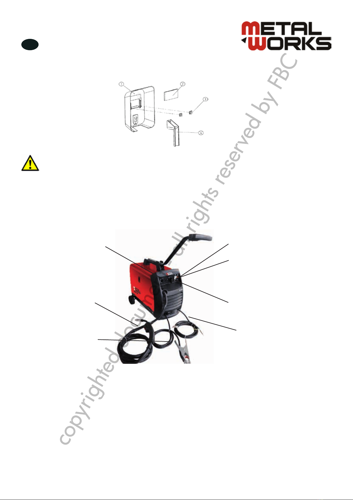
Assemblage van de masker (afb� 6)
--
14
Cautions
Chapter2 Assembly
Diagram 2-7
Do not operate the machine when the shell has been opened, improper
cooling can damage the parts, make sure the sideboard have been closed. When
welding, you must wear helmet、glove and other guard.
Afb. 6
Draadsnelheid
regeling
Toortskabel
Massakabel
Overbelastingsindicator
ON/OFF schakelaar
Instelknop
Netsnoer
AANDACHT!
Schakel het toestel niet in als de behuizing open is� Een onvoldoende koeling kan
onderdelen beschadigen� Verzeker u ervan, dat de zijkant gesloten is� Draag een
masker, handschoenen en andere beschermingen tijdens het lassen�
4 Gebruik
4�1 Bedieningspaneel
ON/OFF schakelaar
Wanneer de schakelaar op OFF staat betekent het dat de stroomtoevoer onderbroken is. Wanneer de
schakelaar op ON staat betekent het dat de transformator en controlecircuit met elektriciteit geleverd worden.
Instelknop
De instelknop heeft 8 posities. Stel de lasstroom in functie van het te lassen staal in. Raadpleeg de tabel op
pagina 10. Fijne metalen vereisen een lage lasstroom, zwaardere metalen een hogere lasstroom.
Afb. 7
copyrighted document - all rights reserved by FBC

MIG150 - NLFRENES - v1.0 - 12112013
10
NL
®
Vergelijkende tabel voor lasstroom regeling:
MIG 150
Regelingsstap DUTY Lasstroom in A
MAX-2 10% 120 A
MAX-1 95 A
MIN-2 60% 51 A
MIN-1 35 A
Overbelastingsindicator
Als u met een hoge amperage voor een lange tijd last, en de inschakelduur overschrijdt, zal de indicator
geel oplichten, en het toestel zal stoppen totdat het weer een veilige temperatuur bereikt. Wanneer de
overbelastingsindicator oplicht, zet de schakelaar op OFF en wacht ongeveer 15 minuten voor het werk te
hervatten.
Grasche symbolen en technische gegevens
--
17
MIG-105
Adjustment step
DYTY
Welding Current in Amps
MAX-2
10%
70A
MAX-1
55A
MIN-2
30%
40A
MIN-1
60%
28.6A
3.1.3 Overload light
If welding with large current for a long time and exceed the duty cycle, the overload lamp will
light (yellow), the machine will stop working until looking to the stated temperature. When the
overload lamp lights you must turn the switch to “OFF” position and wait about 15 minutes, thenyou
can continue.
3.2 Graphic symbols and technical data
U0……
.V This symbol shows the secondary no-load voltage (in volts).
X
This symbol shows the rated duty cycle.
I2……
A This symbol shows the welding current in AMPS.
U2……
V This symbol shows the welding voltage in VOLTS.
U
1 This symbol shows the rated supply voltage.
I1max…
A This symbol shows the welding unit’s maximum absorbed current in AMP.
I1eff…
A This symbol shows the welding unit’s maximum absorbed current in AMP.
IP21 This symbol shows the welding unit’s protection class.
This symbol shows that the welding unit is suitable for use in environments
where there is a high risk of electric shocks.
This symbol shows read the operating instructions carefully before operation.
This symbol shows the welding unit is a single phased D.C. welder.
Chapter3 Operation
This symbol shows the supply power phase and line frequency in Hertz.
This symbol shows the welding unit is a MIG/MAG welder.
3.3 operation process
If use solid wire, need gas to protect, connect mixed gas windpipe of argon/CO2to the tie-in that
on the back of the machine, and tighten it avoid leaking. If use flux wire, you need not these process,
connection of output cable can be changed according to wire types. When use solid wire, as diagram
3-2A, grounding cable connect the “-”, another cable (welding torch cable) connect “+”; When use
flux wire, as diagram 3-2B, grounding cable connect “+”terminal, another cable (welding torch cable)
connect “-”terminal.
S
--
17
MIG-105
Adjustment step
DYTY
Welding Current in Amps
MAX-2
10%
70A
MAX-1
55A
MIN-2
30%
40A
MIN-1
60%
28.6A
3.1.3 Overload light
If welding with large current for a long time and exceed the duty cycle, the overload lamp will
light (yellow), the machine will stop working until looking to the stated temperature. When the
overload lamp lights you must turn the switch to “OFF” position and wait about 15 minutes, thenyou
can continue.
3.2 Graphic symbols and technical data
U0…….V This symbol shows the secondary no-load voltage (in volts).
XThis symbol shows the rated duty cycle.
I2……A This symbol shows the welding current in AMPS.
U2……V This symbol shows the welding voltage in VOLTS.
U1 This symbol shows the rated supply voltage.
I1max…A This symbol shows the welding unit’s maximum absorbed current in AMP.
I1eff…A This symbol shows the welding unit’s maximum absorbed current in AMP.
IP21 This symbol shows the welding unit’s protection class.
This symbol shows that the welding unit is suitable for use in environments
where there is a high risk of electric shocks.
This symbol shows read the operating instructions carefully before operation.
This symbol shows the welding unit is a single phased D.C. welder.
Chapter3 Operation
This symbol shows the supply power phase and line frequency in Hertz.
This symbol shows the welding unit is a MIG/MAG welder.
3.3 operation process
If use solid wire, need gas to protect, connect mixed gas windpipe of argon/CO2to the tie-in that
on the back of the machine, and tighten it avoid leaking. If use flux wire, you need not these process,
connection of output cable can be changed according to wire types. When use solid wire, as diagram
3-2A, grounding cable connect the “-”, another cable (welding torch cable) connect “+”; When use
flux wire, as diagram 3-2B, grounding cable connect “+”terminal, another cable (welding torch cable)
connect “-”terminal.
S
Dit symbool geeft de nullastspanning in V aan.
Dit symbool geeft de nominale inschakelduur aan.
Dit symbool geeft de lasstroom in A aan.
Dit symbool geeft de lasspanning in V aan.
Dit symbool geeft de nominale voedingsspanning aan.
Dit symbool geeft de maximale opgenomen stroom in A aan.
Dit symbool geeft de maximale effectieve voedingsstroom in A aan.
Dit symbool geeft de beschermingsklasse aan.
Dit symbool geeft aan dat het lastoestel in een omgeving met een hoog risico op
elektrische schokken gebruikt kan worden.
Dit symbool geeft aan dat u de handleiding moet raadplegen.
Dit symbool geeft aan dat het lastoestel met DC werkt.
Dit symbool geeft het aantal fasen en de frequentie van de lijn in Hz aan.
Dit symbool geeft aan dat dit een MIG/MAG lastoestel is.
copyrighted document - all rights reserved by FBC
MIG150 - NLFRENES - v1.0 - 12112013
11
NL
®
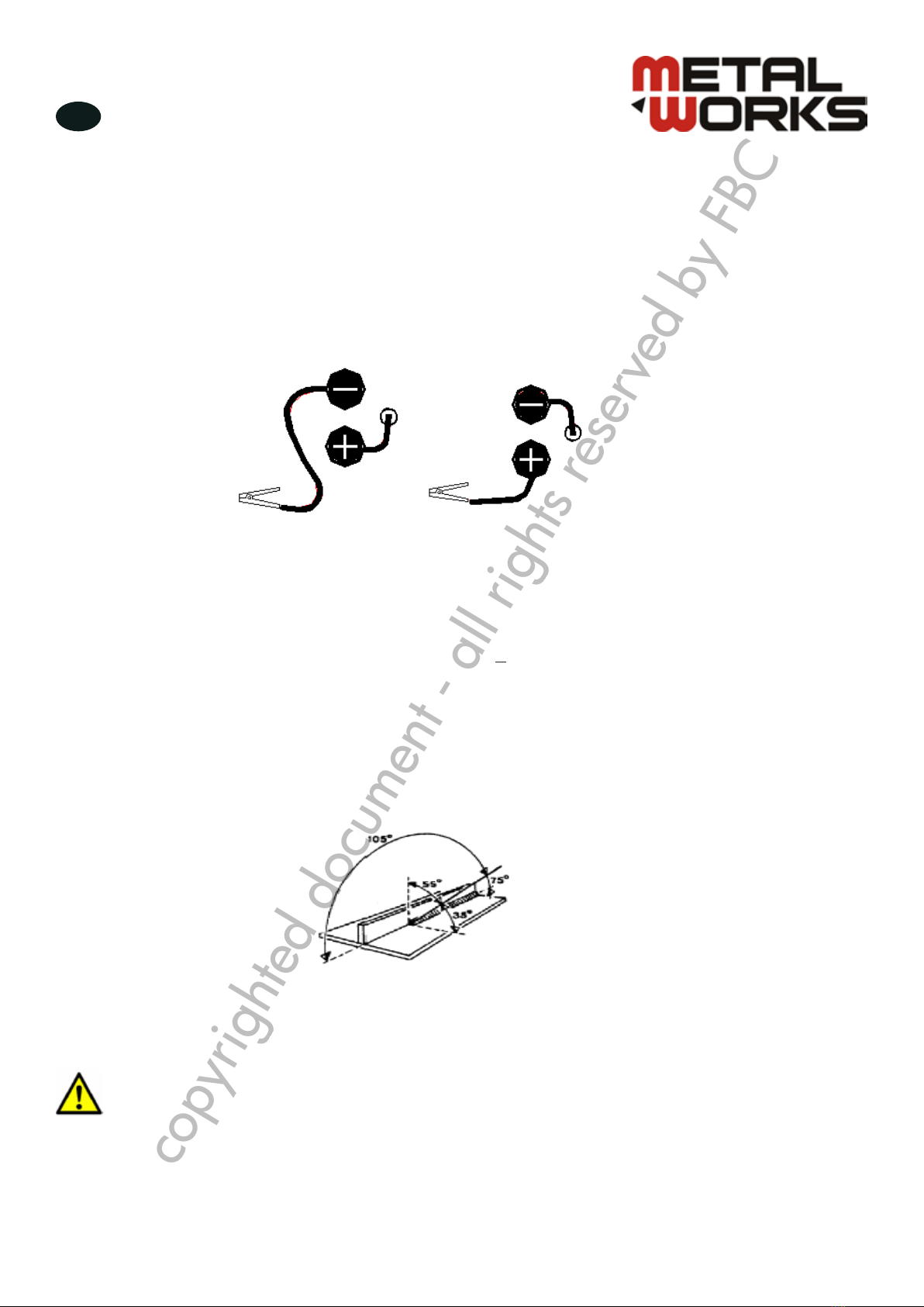
4�2 Lasproces
Als u met massieve draad werkt, moet u beschermgas gebruiken. Sluit een gemengde Argon/CO2 gasslang
aan de achterkant van het toestel aan. Maak zeker dat er geen lekkage is.
Als u Flux draad gebruikt is dit niet nodig. De aansluiting van de uitgangskabel kan in functie van het soort
draad aangepast worden.
Als u massieve draad gebruikt (afb. 8A), verbind de massakabel met de “-” aansluiting en een andere kabel
(toortskabel) met de “+” aansluiting. Als u ux draad gebruikt (afb. 8B), verbind de massakabel met de “+”
aansluiting en een andere kabel (toortskabel) met de “-” aansluiting.
--
18
A B
Diagram 3-2
Step1: Use ground clamp to connect the grounding cable and work piece or connect the metal
carriages (as work table) make sure the clamp has been contacted fully with work piece and clear the
rust and paint.
Step2: According to metal specification, adjust the position of “MIN/MAX”and “1/2 ”switch.
Step3: Check the position of power switch, position must be on “OFF”, then insert the inlet wire to the
socket (voltage is 230 or 115 VAC, rated current of socket ≥15A).
Step4: Discharge the nozzle cover and contact tip at the head of welding torch, pull the soft pipe.
Step5: The welding tongs that clamp the rod can’t be contacted with any grounding objects then turn
the conversion switch to voltage position (the same with input voltage) the power lamp (green) will
light.
Step 6: Press (and hold) the torch button until distance between wire and welding torch is 30mm
loosen torch button.
Step7: Close the power; fix the contact tip and nozzle cover onto the welding torch. (wire must
through the contact tip and nozzle cover)
Step8: Open the power, press the switch spasmodically, adjust the speed by turning the adjusting
wire feed speed knob.
Step9: Orient yourself on the area to be welded, and then place the Face Shield over your eyes.
Step10: Press (and hold) the torch button and stroke the area to be welded with the electrode wire
to ignite the arc.
Step11: Once the arc is ignited, tilt the electrode wire forward at an angle of approximately 35o.(as
diagram 3-3)
Chapter3 Operation
Diagram 3-3
Step12: When the weld is complete, lift the electrode wire clearly away form any grounded object, set
Afb. 8
1. Gebruik de massaklem om de massakabel met het werkstuk of een andere metallische geleider (zoals de
werktafel). Maak zeker dat de klem goed op het werkstuk aangesloten is en verwijder roest en verf.
2. Stel de lasstroom in afhankelijk van het soort metaal.
3. Zorg ervoor dat de schakelaar op OFF staat.
Sluit het netsnoer (230 V of 115 VAC, nominale stroom > 15 A).
4. Druk op de knop van de toorts en laat deze ingedrukt, totdat de afstand tussen de draad en de toorts 30
mm bedraagt.
5. Druk schokkerig op de schakelaar, stel de draadaanvoersnelheid door de instelknop te draaien.
6. Oriënteer uzelf naar de te lassen zone en zet de masker voor uw gezicht.
7. Druk de knop van de toorts (en laat deze ingedrukt) en richt de draad naar de te lassen zone om de boog
te ontsteken.
8. Zodra de boog ontstoken is, kantel de draad naar voren onder een hoek van ongeveer 35° (afb. 9).
9. Wanneer het lasproces voltooid is, verwijder de draad van geaarde voorwerpen, verwijder uw masker en
zet de hoofdschakelaar op OFF.
10.Trek de stekker van het netsnoer uit het stopcontact.
AANDACHT!
Als u met een hoge amperage voor een lange tijd last, en de inschakelduur
overschrijdt, zal de indicator geel oplichten, en het toestel zal stoppen totdat
het weer een veilige temperatuur bereikt� Wanneer de overbelastingsindicator
oplicht, zet de schakelaar op OFF en wacht ongeveer 15 minuten voor het werk te
hervatten�
--
18
A B
Diagram 3-2
Step1: Use ground clamp to connect the grounding cable and work piece or connect the metal
carriages (as work table) make sure the clamp has been contacted fully with work piece and clear the
rust and paint.
Step2: According to metal specification, adjust the position of “MIN/MAX”and “1/2 ”switch.
Step3: Check the position of power switch, position must be on “OFF”, then insert the inlet wire to the
socket (voltage is 230 or 115 VAC, rated current of socket ≥15A).
Step4: Discharge the nozzle cover and contact tip at the head of welding torch, pull the soft pipe.
Step5: The welding tongs that clamp the rod can’t be contacted with any grounding objects then turn
the conversion switch to voltage position (the same with input voltage) the power lamp (green) will
light.
Step 6: Press (and hold) the torch button until distance between wire and welding torch is 30mm
loosen torch button.
Step7: Close the power; fix the contact tip and nozzle cover onto the welding torch. (wire must
through the contact tip and nozzle cover)
Step8: Open the power, press the switch spasmodically, adjust the speed by turning the adjusting
wire feed speed knob.
Step9: Orient yourself on the area to be welded, and then place the Face Shield over your eyes.
Step10: Press (and hold) the torch button and stroke the area to be welded with the electrode wire
to ignite the arc.
Step11: Once the arc is ignited, tilt the electrode wire forward at an angle of approximately 35o.(as
diagram 3-3)
Chapter3 Operation
Diagram 3-3
Step12: When the weld is complete, lift the electrode wire clearly away form any grounded object, set
Afb. 9
copyrighted document - all rights reserved by FBC

MIG150 - NLFRENES - v1.0 - 12112013
12
NL
®
5 Onderhoud
AANDACHT!
Als het toestel niet correct werkt, stop onmiddellijk met werken en zoek naar
de oorzaak van het probleem� Het onderhoud en de reparaties moeten door
gekwaliceerd personeel uitgevoerd worden. Gebruik alleen originele onderdelen
voor de reparaties�
AANDACHT!
Voor elk onderhoud, zorg ervoor dat het toestel van het stroomnet ontkoppeld is�
5�1 Reiniging
• Gebruik schone en droge lage druk perslucht om stof en vuil van de binnen- en buitenkant van het toestel
te blazen. Reinig het uiteinde van de lastoorts. De frequentie van de onderhoudswerkzaamheden is
afhankelijk van de gebruiksomstandigheden.
• Voor een goede ventilatie van het toestel moeten de ventilatieopeningen steeds vrij blijven.
• Na de reiniging met lage druk, controleer dat alle slangen en elektrische aansluitingen goed bevestigd
zijn. Controleer de kabels. Als een kabel beschadigd is, vervang deze onmiddellijk.
5�2 Controle en onderhoud
Bewaar het lastoestel op een droge plaats, reinig vet en zorg ervoor, dat het door gesmolten metaal of vonken
niet beschadigd kan worden.
Transformator
De transformator vereist geen speciaal onderhoud, alleen het verwijderen van stof en vuil door middel van
lage druk perslucht.
De spoel vervangen
Wanneer de spoel leeg is, vervang deze zoals beschreven in paragraaf 3.3.
Kabel
Bewaar de kabel op een schone en droge plaats.
copyrighted document - all rights reserved by FBC

MIG150 - NLFRENES - v1.0 - 12112013
13
NL
®
6 Storingen
AANDACHT!
Trek de stekker voor elke reparatie�
Reparaties op de elektrische uitrusting moeten door een gekwaliceerde elektricien
uitgevoerd worden�
Als het lastoestel niet correct werkt, raadpleeg de onderstaande tabel op de oorzaak te vinden en de storing
op te lossen. Als u het probleem niet dadelijk kunt identiceren, open het toestel om alle onderdelen te
controleren.
Storing Oorzaak Oplossing
Geen stroom - Geen stroom op de stroomvoeding.
- Zekering of stroomonderbreker defect.
- Bescherming tegen overbelasting.
- Controleer de zekering en de
stroomonderbreker.
- Vervang de zekering of de
stroomonderbreker.
- Laat afkoelen en daarna hervat het
werk
De draadaanvoer werkt
niet - Te weinig druk.
- De vleugelmoer is los.
- De draad is geoxideerd.
- Bevestig de spoel stevig.
- Draai de vleugelmoer vast.
- Vervang de draadspoel.
Te weinig stroom - De ingangsstroom is te laag.
- Verkeerde aansluiting.
- Een component werd beschadigd.
- Controleer of de ingangsstroom
dezelfde is als de nominale stroom.
- Controleer de massakabel op goede
aansluiting.
- Vervang de kabel.
De lasdraad is sponzig - Geen of te weinig gas.
- Het gat is verstopt.
- De klep is geblokkeerd.
- Het gas en de draad zijn defect.
- Controleer de gasinlaat.
- Ontstop met perslucht.
- Open de toorts en controleer.
- Het gas moet droog zijn, gebruik een
ander soort draad.
Het toestel werkt niet
wanneer de schakelaar
bediend wordt
- De bedieningskabel is afgebroken.
- Printplaat beschadigd. - Neem contact op met een elektricien.
- Vervang de printplaat.
copyrighted document - all rights reserved by FBC

14
®MIG150 - NLFRENES - v1.0 - 12112013
FR
Table des matières
1 Sécurité����������������������������������������������������������������������������� 15
1.1 Consignes générales de sécurité ............................................... 15
1.2 Sécurité pendant le soudage .................................................... 16
2 Description du produit������������������������������������������������������� 18
2.1 Applications ........................................................................... 18
2.2 Données techniques................................................................. 18
2.3 Caractéristiques de courant et voltage de l’alimentation................ 18
2.4 Conditions environnementales................................................... 18
2.5 Émissions sonores.................................................................... 19
2.6 Sécurité.................................................................................. 19
2.7 Accessoires ............................................................................ 19
3 Assemblage�����������������������������������������������������������������������19
3.1 Exigence pour l’espace d’installation ......................................... 19
3.2 Contrôle et déballage.............................................................. 19
3.3 Installation.............................................................................. 19
4 Opération ������������������������������������������������������������������������� 21
4.1 Panneau de commande ........................................................... 21
4.2 Processus de soudage.............................................................. 23
5 Entretien ��������������������������������������������������������������������������� 24
5.1 Nettoyage.............................................................................. 24
5.2 Contrôle et maintenance .......................................................... 24
6 Dysfonctionnements���������������������������������������������������������� 25
7 Déclaration de conformité CE��������������������������������������������� 50
copyrighted document - all rights reserved by FBC

15
®
MIG150 - NLFRENES - v1.0 - 12112013
FR
1 Sécurité
ATTENTION! Lisez et conservez ces instructions
1�1 Consignes générales de sécurité
Espace de travail
• Gardez l’espace de travail propre et bien éclairé.
• N’utilisez pas d’outils électriques dans un environnement potentiellement explosif, comme en présence de
liquides, gaz ou de poussières inammables.
• Tenez les enfants et spectateurs à l’écart lorsque vous utilisez un outil électrique.
Sécurité électrique
• Branchez votre outil électrique à une prise dont les caractéristiques correspondent à la che de l’outil.
• Évitez le contact du corps avec des surfaces mises à la terre comme des tuyaux, radiateurs, cuisinières et
réfrigérateurs.
• N’exposez pas les outils électriques à la pluie ou à l’humidité.
• Manipulez correctement le cordon d’alimentation. N’utilisez jamais le cordon pour tirer, transporter ou
débrancher l’outil. Maintenez le cordon à l’écart de la chaleur, des huiles, des bords tranchants ou de
pièces mobiles.
• Si vous utilisez un outil électrique à l’extérieur, utilisez une rallonge conçue pour une utilisation à
l’extérieur.
Sécurité personnelle
• Restez vigilant, soyez attentif à ce que vous faites et faites preuve de bon sens lorsque vous utilisez un outil
électrique. N’utilisez pas un outil électrique si vous êtes fatigué ou si vos capacités sont altérées par des
médicaments, des drogues ou de l’alcool.
• Utilisez des équipements de sécurité. Portez toujours des lunettes de protection.
• Évitez les démarrages accidentels. Assurez-vous que le commutateur est sur « off » avant de brancher
l’outil.
• Retirez les outils de réglage avant de mettre en marche l’outil électrique.
• Ne prenez pas de risques. Maintenez les pieds au sol et votre gardez à tout moment un bon équilibre.
• Portez des vêtements appropriés. Ne portez pas de vêtements amples ou des bijoux. Maintenez vos
cheveux, vêtements et gants à l’écart des parties mobiles.
• Si des appareils d’aspiration de la poussière sont fournis, veillez à les brancher et à les utiliser
correctement.
Utilisation et entretien des outils électriques
• Ne forcez jamais un outil électrique. Utilisez l’outil électrique approprié à la tâche.
• N’utilisez pas un outil électrique si le commutateur ne fonctionne pas.
• Débranchez la che de la source d’alimentation avant de faire des modications, de changer les
accessoires ou d’entreposer les outils électriques.
• Entreposez les outils électriques non utilisés hors de la portée des enfants des personnes non autorisées.
• Entretenez vos outils électriques. Vériez les si les pièces mobiles sont bien alignées et xées, contrôlez
qu’aucune pièce n’est cassée et soyez attentif à toute situation pouvant nuire au fonctionnement de l’outil
électrique. S’il est endommagé, faites-le réparer avant de l’utiliser.
• Maintenez les outils de coupe propres et aiguisés.
• Utilisez l’outil électrique, les accessoires, les mèches, etc., selon les instructions et de la manière
appropriée à ce type d’outil électrique, en prenant en compte les conditions de travail et la tâche à
accomplir.
copyrighted document - all rights reserved by FBC
16
®MIG150 - NLFRENES - v1.0 - 12112013
FR
1�2 Sécurité pendant le soudage
Propreté :
• Utilisez de l’air propre et sec pour soufer la poussière et les saletés se trouvant à l’intérieur et à
l’extérieur de l’appareil. Nettoyez la saleté et les dépôts sur les extrémités des pinces. Pour assurer
une bonne ventilation et un refroidissement correct, il est important de laisser les volets d’aération
de l’appareil bien dégagés.
• Vériez si l’isolation du câble est dénudée. Si le câble est efloché, remplacez-le avant utilisation.
• Gardez l’espace de travail propre et bien éclairé. Les endroits encombrés et sombres sont propices
aux accidents. Tenez les enfants et autres personnes non autorisées éloignées de l’espace de
travail. La distraction peut vous faire perdre le contrôle.
Vêtements de protection : Portez des vêtements appropriés pendant les opérations de soudage :
• Les personnes se trouvant dans l’espace de travail doivent porter un masque de soudage, une
visière et des lunettes de protection.
• Utilisez un masque de protection approprié avec ltre pour protéger les yeux, le visage, le cou et
les oreilles des étincelles et du rayonnement de l’arc.
• L’utilisateur ne peut pas regarder directement l’arc et doit garder une distance de sécurité par
rapport au rayonnement de l’arc et aux éclaboussures.
• Portez des vêtements, chaussures et masque de protection pour vous protéger du rayonnement de
l’arc, des pulvérisations et des éclaboussures.
• Fermez tous les boutons pour éviter le contact du corps avec des étincelles et des éclaboussures.
• Utilisez une séparation ininammable pour protéger les autres travailleurs du rayonnement et des
étincelles.
• Portez des lunettes de protection lors du nettoyage des projections de soudure.
Incendie et explosion : La chaleur de l’appareil et de l’arc peut provoquer un incendie.
• Gardez les matériaux inammables tels que le bois, le tissu, les combustible liquides et essences
loin de la zone de travail.
• Le sol et les murs de l’espace de travail doivent être exempts de tout matériel an d’éviter la fumée
et les incendies.
• Assurez-vous que les pièces à usiner sont nettoyées avant le soudage, et ne soudez jamais sur un
conteneur scellé.
• Les moyens de lutte contre l’incendie doivent être placés à proximité de la zone de travail.
• N’utilisez pas l’équipement de sorte qu’il soit en surcharge.
Réparations
• Faites réparer votre outil électrique par un technicien qualié et n’utilisez que des pièces de rechange
originales.
PRÉCAUTIONS
Maintenez à l’écart les enfants et les personnes atteintes d’incapacité�
Lorsque vous ne les utilisez pas, les outils électriques devraient être entreposés hors
de la portée des enfants et des personnes atteintes d’invalidité�
copyrighted document - all rights reserved by FBC
17
®
MIG150 - NLFRENES - v1.0 - 12112013
FR
Chocs électriques : N’utilisez pas le poste à souder dans un environnement humide, pour éviter les
blessures ou la mort.
• Assurez-vous que le système est bien mis à la terre.
• Assurez-vous que le risque d’électrocution est minimisé par l’installation de dispositifs de sécurité
appropriés. Un disjoncteur différentiel (disjoncteur courant résiduel) doit être intégré au tableau
principal. Nous recommandons également l’utilisation d’un disjoncteur avec tous les appareils
électriques. Il est particulièrement important d’utiliser un disjoncteur différentiel avec les appareils
portables branchés sur une alimentation non protégée par un disjoncteur différentiel. En cas de
doute, contactez un électricien.
• Conservez bien au sec les vêtements, la zone de travail, les câbles, la torche, la plaque de soudure
et l’alimentation électrique.
• Gardez le corps isolé de la pièce à usiner.
• L’opérateur doit se tenir sur une planche de bois sec ou une plate-forme isolante s’il travaille dans
une zone humide ou scellée.
• Portez des gants secs et fermés avant d’allumer l’appareil.
Champ électromagnétique : Les travailleurs portant un stimulateur cardiaque doivent consulter
leur médecin avant d’effectuer des travaux de soudure. Le champ électromagnétique peut perturber le
fonctionnement d’un stimulateur cardiaque.
Le travailleur doit prendre les précautions suivantes pour diminuer l’exposition au champ
électromagnétique :
• Mettez la cosse de l’électrode et le câble ensemble. Une bande adhésive peut être utilisée si
possible.
• N’enroulez pas le câble de la torche de soudage ni le câble de travail autour de vous.
• Maintenez le câble de la torche de soudage et le câble de travail d’un côté de vous.
• Tenez-vous autant que possible à l’écart de la source d’énergie et du câble de soudage.
Brouillard et gaz : Le brouillard et le gaz de soudage peut incommoder ou rendre malade
l’opérateur, surtout dans un espace mal ventilé.
• Un aérateur mécanique ou naturel doit être installé dans l’espace de travail. Ne soudez pas les
métaux suivants : acier inoxydable galvanisé, cuivre, zinc, béryllium et le calcium. N’inhalez pas
les brouillards et gaz de soudage.
• Ne soudez pas à proximité d’opérations de dégraissage ou de pulvérisation, pour éviter le
phosgène toxique ou gaz similaires.
• Si vous sentez une irritation des yeux, du nez, etc., arrêtez immédiatement le soudage.
Entretien de l’équipement : Un entretien inadéquat ou insufsant de l’équipement peut causer de
graves blessures, voire la mort.
• Seul du personnel autorisé peut effectuer les opérations d’assemblage et de maintenance.
• La source d’énergie doit être coupée pour effectuer les travaux de maintenance.
• Assurez-vous que le câble, le câble de masse, le connecteur et le câble d’alimentation et
l’alimentation sont en bon état.
• Manipulez toujours correctement l’équipement et les accessoires.
• Rangez le matériel de manière sûre et hors de portée des enfants.
• Ne laissez pas les personnes non familiarisées avec l’outil ou ce mode d’emploi utiliser l’appareil.
Les outils électriques sont dangereux dans les mains d’utilisateurs inexpérimentés.
• Utilisez toujours les accessoires et équipements appropriés.
OPERATORS’ MANUAL · TIG SERIES 2
1. SAFETY
Welding is dangerous, and may cause damage to you and others, so take good protection when welding. For
details, please refer to the operator safety guidelines in conformity with the accident prevention requirements of
the manufacturer.
Professional training is needed before operating the machine.
Use labor protection welding supplies authorized by national
security supervision department.
Operators should be with valid work permits for metal welding
(cutting) operations.
Cut off power before maintenance or repair.
Electric shock—may lead to serious injury or even death.
Install earth device according to the application criteria.
Never touch the live parts when skin bared or wearing wet
gloves/clothes.
Make sure that you are insulated from the ground and workpiece.
Make sure that your working position is safe.
Smoke & gas—may be harmful to health.
Keep your head away from smoke and gas to avoid inhalation of
exhaust gas from welding.
Keep the working environment well ventilated with exhaust or
ventilation equipment when welding.
Arc radiation—may damage eyes or burn skin.
Wear suitable welding masks and protective clothing to protect your
eyes and body.
Use suitable masks or screens to protect spectators from harm.
Improper operation may cause fire or explosion.
Welding sparks may result in a fire, so please make sure no
combustible materials nearby and pay attention to fire hazard.
Have a fire extinguisher nearby, and have a trained person to use it.
Airtight container welding is forbidden
Do not use this machine for pipe thawing.
Hot workpiece may cause severe scalding.
Do not touch hot workpiece with bare hands.
Cooling is needed during continuous use of the welding torch.
Noise may be harmful to people’s hearing.
Wear approved ear protection when welding.
Warn spectators that noise may be harmful to their hearing.
Magnetic fields affect cardiac pacemaker.
Pacemaker users should be away from the welding spot before
medical consultation.
copyrighted document - all rights reserved by FBC

18
®MIG150 - NLFRENES - v1.0 - 12112013
FR
2 Description du produit
2�1 Applications
Le poste à souder MIG est un produit industriel avec système de dévidage du l. Il est peu encombrant, facile
à déplacer et à utiliser. Il est conçu pour le soudage d’aciers à faible teneur en carbone, aciers faiblement
alliés et autres.
2�2 Données techniques
2�3 Caractéristiques de courant et voltage de l’alimentation
La courbe de la gure 1 illustre la caractéristique statique externe de la puissance de soudage. Elle montre la
tension de sortie que l’on obtient pour chaque courant de sortie préréglé.
--
9
Chapter1 Product description
1.1 Produce application
MIG series welding machine adopt special tapped transformer adjusting style. It is an industrial
product, it have wire-feed system, small volume, easy to shift and simple operation, it apply to welding
low-carbon steel、low-alloy steel and so on.
1.2 Model unit
--
10
1.3 Voltage characteristic and current characteristic of welding power source
The curve (as diagram1-1) means “V-A” external static characteristic of welding power, gradient of
cure named slope, normal means “drop off voltage per 100A”. The curve shows the output voltage we
can get in any preset output current because the “V-A” slope id fixed.
Diagram 1-1External static characteristic
Chapter1 Product description
1.4 Equipment condition
a) Surrounding temperature range
During welding: -10℃~+40℃
During transit and storage: -25℃~+55℃
b) Opposite humidity
when 40℃<50%
when 20℃<90%
c) Dust acid active gas or object in surrounding air can’t exceed normal content, except these
objects that be brought by welding course.
d) Altitude height must ≤1000m
e) Gradient of welding power ≤15°
1.5 Noise announce
When the machine working, it maybe have noise, but the noise can’t exceed 75 decibel.
1.6 Safety
Before operating the equipment, you must read the safety directions to avoid the hurt that
because of misapply and impropriety in stalling.
1.7 Accessories
1.7.1 Hammer brush
In order to operate the machine confidently, our company will give you one hammer and one
brush as present.
Fig. 1: Caractéristique statique externe
2�4 Conditions environnementales
Température
Température de service : -10°C ~ +40°C
Température de transport et de stockage : -25°C ~ +55°C
Humidité
Par 40°C < 50%
Par 20°C < 90%
Altitude
< 1000 m
Gradient de puissance de soudage
< 15°
copyrighted document - all rights reserved by FBC

19
®
MIG150 - NLFRENES - v1.0 - 12112013
FR
2�5 Émissions sonores
Lorsque l’appareil fonctionne, il peut émettre du bruit, mais jamais au-delà de 75 dB.
2�6 Sécurité
Avant d’utiliser l’équipement, vous devez avoir lu les instructions et consignes de sécurité pour éviter les
accidents dus à une mauvaise installation ou utilisation.
2�7 Accessoires
• Brosse/marteau à piquer
• Masque avec verre de soudure noir
• Pointe de contact
• Bobine de l fourré 0,8 mm
• Torche MIG avec 2,1 m de câble
• Pince de masse avec 1,8 m de câble
3 Assemblage
3�1 Exigence pour l’espace d’installation
Le sol doit être égal et l’espace de travail doit être bien ventilé. Il ne peut pas être exposé à la poussière, à
la saleté, à l’humidité. La distance minimale entre le panneau arrière et le mur le plus proche doit être d’au
moins 46 cm.
3�2 Contrôle et déballage
• Dès la réception de l’appareil, vériez s’il n’y a pas eu de dégâts de transport. Si vous constatez des
dommages ou des pièces manquantes, signalez-le immédiatement au revendeur ou au transporteur.
• Déballez les pièces détachées, retirez les matériaux d’emballage et vériez qu’ils sont bien vides.
• Contrôlez toutes les sorties d’air dans le corps de l’appareil, en vous assurant que des parties d’emballage
ne les bouchent pas.
• Choisissez un endroit spacieux pour l’installation, an d’avoir assez de place pour le matériel.
3�3 Installation
Fixer la bobine de l
Important: Type de l : l fourré (E71-GS) en acier
Diamètre du l : 0,6 mm à 0,8 mm
Diamètre de la bobine : 200 mm
Poids maximum de la bobine (l inclus) : 5 kg
Vitesse de dévidage : 1,8 m/min ~ 15 m/min
copyrighted document - all rights reserved by FBC

20
®MIG150 - NLFRENES - v1.0 - 12112013
FR
1. Ouvrez le panneau droit et dévissez l’écrou à ailettes de l’axe de la bobine.
2. Placez successivement le ressort et la bobine de l sur l’axe, puis replacez
l’écrou à ailettes (g. 2).
--
12
Step 2: Hold the spring and wire spool into wire-feed spool axle successively, and then hold the
wing nut (as diagram 2-3).
Diagram 2-3
Step 3: Open the wire-feed impaction equipment (C), let the terminal of wire through godet tube,
wire-feed wheel, and import the godet tube of welding torch, then close the equipment(c), adjust
the impaction nut of wire-feed wheel (as diagram 2-4).
Diagram 2-4
Step 4: Close the right sideboard
Chapter2 Assembly
2.3.3 Gas cylinder installation
The welder has a platform on the rear of the machine to support a gas cylinder. See diagram 2-5
for reference. If you plan on moving your welder about the shop, use only small cylinders (outside
diameter=140mm, 320mm≤height≤500mm, weight≤10Kg, service pressure≤20Mpa) for transport
safety. Large cylinders (outside diameter>140mm , or height>500mm, or weight>10Kg, service
pressure≤20Mpa) should be secured in a permanent location or to a separate cart, not to the welder.
Secure the small size cylinder with the gallus supplied with the welder. Small cylinders can be easily
secured in place using the top rack “A”.
Fig. 2
Fig. 3
3. Ouvrez le dispositif de dévidage, passez l’extrémité du l par le tube, la roue
de dévidage et introduisez le tube de la torche de soudage, puis refermez le
dispositif. Ajustez l’écrou de la roue de dévidage (g. 3).
4. Refermez le panneau latéral.
--
13
Diagram 2-5
2.3.4 Connection welder to gas cylinder
Clean the threads of the gas cylinder valve. Also open the gas valve for a few seconds to blow out
any dirt of particulates which may have gotten into the orifice in order to prevent them from entering
the regulator. Check your regulator (outlet flow meter: 0-25L/Min, inlet gauge: 0-25Mpa, pressure
range for safe outpouring: 0-0.35Mpa) to make sure that it was supplied with a gasket.
Tighten the regulator coupling to the cylinder gas valve. Now connect the welder gas line to the hose
barb outlet on your regulator; a stainless steel hose clamp can be used to insure a leak-proof
connection. (See diagram 2-6)
Check all connections for leaks by opening the regulator and cylinder gas valves.
When the machine is not in use, always shut off the regulator and cylinder gas valves.
Diagram 2-6
2.3.5Fixing the face shield (as diagram 2-7)
Fig. 4
Fig. 5
Installation de la bouteille de gaz
À l’arrière de l’appareil, il y a une plate-forme qui sert de support pour la
bouteille de gaz (g. 4). Si vous prévoyez de déplacer votre poste à souder
dans l’atelier, utilisez des petites bouteilles (diamètre de 140 mm, hauteur < 500
mm, poids < 10 kg, pression de service < 20 MPa). Les plus grandes bouteilles
doivent être sécurisées dans un endroit xe ou sur un chariot séparé, pas sur
l’appareil. Fixez les petites bouteilles sur l’appareil au moyen des attaches
fournies. Panneau
Attache
Connexion de l’appareil à la bouteille de gaz
Nettoyez le let de la vanne de la bouteille. Ouvrez le robinet de gaz
pendant quelques secondes pour laisser s’échapper les particules de
saleté qui pourraient être entrées dans l’orice et les empêcher ainsi
d’entrer dans le régulateur.
Contrôlez le régulateur (débit de sortie: 0-25 l/min, jauge d’entrée :
0-25 MPa, plage de pression : 0-0,35 MPa), pour être sûr qu’il a été
livré avec un joint.
Fixez le raccord du régulateur à la vanne de la bouteille de gaz.
Connectez à présent le tuyau de gaz de l’appareil sur le raccord
cannelé du régulateur. Un collier de serrage peut être utilisé pour une
xation bien étanche (g. 5).
Vériez toutes les connexions pour vérier l’absence de fuite quand vous
ouvrirez les vannes du régulateur et de la bouteille.
Lorsque l’appareil n’est pas utilisé, fermez toujours les vannes du
régulateur et de la bouteille de gaz.
Bouteille
de gaz
Tuyau de gaz
Raccord cannelé
Régulateur
copyrighted document - all rights reserved by FBC
This manual suits for next models
1
Table of contents
Languages:
Other Metalworks Welding System manuals


Popular Welding System manuals by other brands


HOGERT
HOGERT HT1P680 user manual

XTline
XTline XT103001 Operation manual

MK Products
MK Products CobraTig-150 CALIBRATION PROCEDURE

Capacitor Discharge
Capacitor Discharge 3300828-F instruction manual

Chicago Electric
Chicago Electric 62486 Owner's manual & safety instructions

Lincoln Electric
Lincoln Electric Magnum 300 Operator's manual