Metel OH6425 OG1 User manual

www.metel.eu 1/10 www.iplog.eu
REV-202106
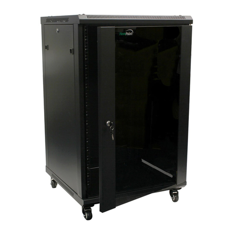
Outdoor Cabinets for OFF-GRID Systems OH6425
OG1
OH6425
OG1 IP66EN 61439-1IEC 61131-3 LTE
v Outdoor Steel IP66 Cabinet
v Durable Epoxy-Polyester Powder Coating
v Supplied Cabinet’s Equipments
- MPPT Charger
- Overvoltage Protection of Power from PV Panels
- Shelf for 60 Ah Battery
- Outdoor Antenna
- Overpressure Fuse
- Lock with two Keys
- DIN35 Rail, Terminals, Fuses and Internal Cabling
- PoE+ Injector
- Overvoltage Protection of LAN Input/PoE+ Output
v Optional Accessories
- Mounting Kit for Installing the Cabinet on a Wall
- Mounting Kit for Installing the Cabinet on a Pole
PRODUCT NAME CODE NOTE
OH6425-OG1-LTE 4-000-005 2G/3G/4G-LTE
OH6425-OG1-LTE-POE 4-000-006 2G/3G/4G-LTE
OH6425-OG1-LTE Yes Yes No No
OH6425-OG1-LTE-POE Yes Yes Yes Yes
MPPT Charger Power Surge Protection PoE+ Injector LAN Surge Protection
Block Connection of OH6425-OG1-LTE-POE Version with PLC IPLOG
Cabinets are a flexible solution for island monitoring and controlling systems. The modular PLC IPLOG
offers a wide range of inputs, outputs and communication interfaces. Thanks to this, the customer can
build a system exactly to their specifications.
Supplied Equipment
The Cabinets are supplied include the interconnected and tested equipments listed in the table below.
The exact PLC model is ordered separately. Selecting the PLC is recommended in the online configurator
available at http://www.metel.eu/en/iplog-configurator. Refer to page 2 for recommended battery types
and PV panels.
KIT-OH 4-500-033 Wall Mounting Kit
Holder-OH6425 4-500-030 Pole Installation Kit
Fuses
PV Panels
Overvoltage
Protections
Gel 12V
Battery
MPPT
Charger
Fuses
Dual LTE
Antenna
PoE Camera PoE+
Injector PLC
IPLOG
Wide
Range of
Selected
Inputs and
Outputs
RE
DO
AO
AI
DI
Modbus, Dali,
Bacnet and
other Serial
Interfaces
PROTECTEDSIDE
SURGE ARRESTER – ETHER NET
OVP-100M-H IPOE-BOX C OD E:4-448-104

www.metel.eu 2/10 www.iplog.eu
REV-202106
Outdoor Cabinets for OFF-GRID Systems OH6425
OG1
OH6425
OG1 IP66EN 61439-1IEC 61131-3 LTE
Example of Dimensioning a 12V OFF-GRID System with a Fixed PoE Camera
Step 1: Calculate the Energy of the System
First, find out the maximum power consumption of the connected devices and calculate the daily
consumption of the system from it.
Example:Camera MOBOTIX M26 - power consumption until 5 W,
PLC IPLOG with LTE IPLOG-G3-21 - power consumption until 4 W,
PoE+ Injector POE-PSE-30 - power consumption until 1W.
Max. power consumption of connected devices = 10W a Daily system consumption = 10 x 24 = 240 Wh
&There are situations where it is not necessary to have all devices functional in 24/7 mode, but it is
enough to turn them on only when needed. In such situations, we recommend using the PLC control
program, which switches individual devices on / off as required.
Step 2: Calculate the Sizeof the Panels and the Backup Battery
An online form is available at https://re.jrc.ec.europa.eu/pvg_tools/en/, where you can find out after
selecting the installation site, setting the daily system consumption, battery capacity, panel performance
and clicking on Visualize results whether the selected combination is suitable. By gradually adjusting the
selected values, you will get to the optimal values that will suit the given system.
Step 3: Select Suitable Types of Panels and Backup Battery
We recommend using BlueSolar polycrystalline panels or other panels with similar
parameters as the energy source. The panels are suitable for systems with a working
voltage of 12V. If more power is needed, it is possible to connect the panels in parallel
and in series, provided that the maximum no-load voltage does not exceed 75V.
The system must be backed up with a high-quality battery suitable for cyclic
operation, such as 60Ah Victron batteries type BAT412550084. The critical period for
the battery is the winter period, when the charging time is reduced to a maximum of 6
hours between 10 am and 4 pm (Central Europe). In addition, due to low
temperatures, the capacity drops by up to 50% at −20°C. Components of the
switchboards include shelves for placing the accumulator and an overpressure fuse
enabling pressure equalization if the accumulator produces hydrogen during charging.
Step 4: Provide Surge Protection
A direct lightning strike on unprotected devices can destroy them. A suitable solution
is to ground the mast and to comply with other recommendations given in the
standard ČSN EN 62305. In general, it is important that all electronic devices are
hidden in the protective angle of the collector.
Compared to systems powered from a 230V network, solar OFF-GRID systems have a
significant disadvantage in an unstable energy supply, which is largely dependent on
the weather at the installation site. When designing, it is necessary to take into
account the changing amount of incident solar energy during the year. The EU
website (https://ec.europa.eu/jrc/en/pvgis) focusing on photovoltaic systems is
therefore a great simplification of this proposal. It contain detailed maps of sunshine
for the whole of Europe and the surrounding areas, including online forms for
calculating the size of photovoltaic panels and batteries.

www.metel.eu 3/10 www.iplog.eu
REV-202106
Outdoor Cabinets for OFF-GRID Systems OH6425
OG1
OH6425
OG1 IP66EN 61439-1IEC 61131-3 LTE
PLC IPLOG
with LTE Modem,
Inputs, Outputs
and Buses
Dual LTE
Antenna
Pressure
Fuse
PoE+
Injector
MPPT
Charger
Overvoltage
Protection
LAN and PoE
Overvoltage
Protection
of Power Input
Fuses for Power
Input and Battery
Tamper
Glands
PG11
Backup
Battery
Protocol Test
Report and Wiring
Diagram
Lock Key
Lockable
Cabinet with Bracket from the
KIT-OH Wall Mounting Kit
Cabinet with Bracket from the
Pole Mounting Kit
Equipment Detail OH6425-OG1-LTE-POEEquipment Detail OH6425-OG1-LTE-POE

www.metel.eu 4/10 www.iplog.eu
REV-202106
Outdoor Cabinets for OFF-GRID Systems OH6425
OG1
OH6425
OG1 IP66EN 61439-1IEC 61131-3 LTE
Parameter Values Unit Notes
Material Galvanized Steel
Dimensions - H / W / D 600 x 400 x 250 mm
Surface Finish Epoxy-Polyester Powder Enclosure Grey RAL 7035
PoE + Injector POE-PSE-30-BOX (Available Only in Version OH6425-OG1-LTE-POE)
Weight Max. 50 kg With Equipment
Mechanics Glands 8 ks PG11
Power Inputs Number and Type 1x Input for Connecting PV Panels
Input Voltage Max. 75VDC VDC
Protection Fuses 2x 20 A Size 10×38 mm
IP Code IP66
PoE Pins 4-5, 7-8 PoE 48 VDC PoE mode B
DataPins 1-2, 3-6 Ethernet 10/100 Mbps
Input Voltage 10 - 30 VDC
Holder-OH6425 PermissibleLoad 50 kg Pole Installation Kit
The producer retains the right to change anytechnical parameters without previous written or published notification.
Pole Diameter 150 - 215 mm
KIT-OH PermissibleLoad 50 kg Wall Mounting Kit
Tamper Door Closed = Closed Contact
Battery Protection Fuses 2x 20 A Size 10×38 mm
Supported Batteries 12/24 V Autodetection
Antennas LTE Version Outdoor Antenna2G/3G/4G-LTE Connection SMA Connectors
Recommended Type of Batteries Victron Energy GEL 60Ah or any other suitable for cyclic operation
Charging Current Max. 15 A
Absorption Voltage 14,4 / 28,8 V 12 / 24V Battery
Floating Voltage 13,8 / 27,6 V 12 / 24V Battery
Charging Temp. Compensation - 16 mV/°C / – 32 mV/°C 12 /24 V Battery
Maximum Efficiency 98 %
Operating Temperature –30 ... +60 °C Full power up to max. 40°C
Charging Charger Technology MPPT
Technical Parameters
Max. Power Consumption 20 mA
VOut 52 VDC max. 0.3A
Max. Delivered Power 30 W∑ PoE + VOut
Operating Temperature –40 ... +70 °C
SurgeProtection LAN + PoE OVP-100M-HIPOE
Battery Maximum Dimensions W / H / D 250 x 245 x 205 mm
Recommended Battery Victron 60 Ah BAT412550084 Not Included
SurgeProtection Type I + II 6,5 kA in wave 10/350µs
Recommended PE Conductor 10 - 16 mm²PETerminal at Bottom Left

www.metel.eu 5/10 www.iplog.eu
REV-202106
Outdoor Cabinets for OFF-GRID Systems OH6425
OG1
OH6425
OG1 IP66EN 61439-1IEC 61131-3 LTE
OH6425-OG1-LTE - Cabinet with PLC, Charger and Protections

www.metel.eu 6/10 www.iplog.eu
REV-202106
Outdoor Cabinets for OFF-GRID Systems OH6425
OG1
OH6425
OG1 IP66EN 61439-1IEC 61131-3 LTE
OH6425-OG1-LTE-PoE - Cabinet with PLC, Charger, Protections and Injector

www.metel.eu 7/10 www.iplog.eu
REV-202106
Outdoor Cabinets for OFF-GRID Systems OH6425
OG1
OH6425
OG1 IP66EN 61439-1IEC 61131-3 LTE
OH6425-OG1-LTE-POE - Including Equipment Connection

Quick Installation Manual REV:202106
OH6425-OG1
Outdoor Cabinets for OFF-GRID Systems
www.metel.eu 8/10 www.iplog.eu
Installation
1. Mounting
Use the mounting holes in the corners for mounting.
On a Flat Surface
Use the KIT-OH mounting kit. See page 9.
On the Column
Use the HOLDER-OH6425 mounting kit. Page 10 shows
the connection of the switchboard with U-profiles,
stainless steel strips and a column. The set is intended
only for use on round columns with a diameter in the
range: 150 - 215 mm. The switchboard must always be
installed in a vertical position with the glands facing
downwards. When mounting, use fasteners in accordance
with the instructions in this manual.
2. Grounded Cabinet and Overvoltage Protections
Ground the cabinet with a stranded or solid Cu conductor
with a cross section of 10 - 16mm2. Screw the wire into
the green-yellow terminal block located on the right
of the bottom DIN35 rail. The earth resistance must be
within 10Ω.
3. Battery Connection
In fuse holders with a hinged top cover (power input
is disconnected) connect battery power. Observe the
marked polarity when connecting. Snap on the top fuse
covers. Correct connection is signaled by lighting or
flashing of the green LED on the charger.
4. Connection of Photovoltaic Panels
In fuse holders with a hinged top cover (power input
is disconnected) connect power from photovoltaic panels.
When connecting, observe the polarity marked on the
fuse holders. Snap on the top fuse covers. Check the LED
on the MPPT charger to verify that the connection was
successful. Otherwise, disconnect the power supply,
rectify the fault, and reconnect.
5. Connection of PLC and Other Hardware
The delivery includes the connection of the charger and
other components inside the switchboard. Cables and
wires leading outside the switchboard are installed by the
customer only at the installation site. The PLC is
connected to the terminals .
1
1
2
3 2
3
4
4
• Installation, adjustment and operation may only be performed by a person with appropriate electrical qualifications
• Installation, adjustment and operation may only be performed by a person who is fully acquainted with this manual
• Connecting PV panels and must be installed in accordance with the regulations and standards applicable in the country
• Installation must not be performed during a thunderstorm
• The installation must be complied with safety regulations and standards applicable in the country
Lights
Blinks
Green LED Indicates the battery connection and which load output control algorithm has been selected
The charger is set to a conventional load output control algorithm.
The output load control algorithm is set to BatteryLife.
LED Charger Indication
Off
Fast Blinks
Yellow LED Charging mode indication
No power supply from PV panels (night, low light intensity) or PV panels connected in opposite polarity.
Fast charging phase, batterycharge is between 0% and 80%.
Slow Blinks Absorption charging phase, the stateof charge of the battery is between 80% and 100%.
Lights Maintenance phase of charging, thebattery is fully charged, the state ofchargeis 100%.

Quick Installation Manual REV:202106
OH6425-OG1
Outdoor Cabinets for OFF-GRID Systems
www.metel.eu 9/10 www.iplog.eu
KIT-OH - Accessories for Cabinet Installation on a Flat Surface
Holder from Kit
KIT-OH

Quick Installation Manual REV:202106
OH6425-OG1
Outdoor Cabinets for OFF-GRID Systems
www.metel.eu 10/10 www.iplog.eu
Revision: 201809 – Default
201908 – Stop Production OH6425-OG2-LTE-POEVersion.
202106 – Change MMPT Charger
HOLDER-OH6425 - Accessories for Cabinet Installation on a Pole
Spring Washer
Bolt
Rubber Washer
HOLDER-OH6425
The Wall of the Cabinet
Stainless Steel Washer
HOLDER-OH6425
Bolt Insert
This manual suits for next models
2
Table of contents
