Meteo Control COMFORT User manual

WEB'log Comfort 110621 - en
WEB'log
COMFORT
Operating Instructions

2/53 WEB'log Comfort 110621 - en
Spicherer Str. 48
D-86157 Augsburg
Tel.: +49 (0) 821 / 3 46 66-0
Web: www.meteocontrol.com
Technical Support:
Tel.: +49 (0) 821 / 3 46 66-88
Fax: +49 (0) 821 / 3 46 66-11
© 2011 meteocontrol GmbH
All rights reserved.
All information in these operating instructions has been compiled and
checked with the greatest care and diligence. Nevertheless, the possibility of
errors cannot be entirely excluded. meteocontrol GmbH therefore cannot
accept any liability for errors or any circumstances resulting from errors.
Subject to technical alterations.

WEB'log Comfort 110621 - en 3/53
Contents
1Notes on using the Operating Instructions ..............................4
2Safety instructions...................................................................4
3Overview of the device............................................................5
3.1 Front view ...............................................................................5
3.2 Operator control elements ......................................................6
3.3 Status LED............................................................................12
3.4 Standard scope of supply .....................................................19
3.5 Rating plate...........................................................................19
3.6 Assignment of connections ...................................................20
3.6.1 RS485 / RS422 interfaces ....................................................20
3.6.2 Other interfaces ....................................................................20
3.7 Default settings .....................................................................22
4Installation.............................................................................23
4.1 Safety instructions for installation .........................................23
4.2 Cables and wiring .................................................................24
4.3 Installation.............................................................................25
4.4 Removal................................................................................25
4.5 Interfaces ..............................................................................26
4.5.1 Analog input..........................................................................27
4.5.2 Digital input ...........................................................................27
4.6 Bus communication...............................................................28
4.6.1 General connection diagram.................................................29
4.6.2 Danfoss inverter....................................................................30
4.6.3 Delta inverter ........................................................................31
4.6.4 Diehl AKO Platinum inverter .................................................32
4.6.5 Fronius inverter.....................................................................34
4.6.6 Ingeteam inverter ..................................................................35
4.6.7 Jema inverter ........................................................................36
4.6.8 Kaco inverter.........................................................................36
4.6.9 Mastervolt inverter ................................................................37
4.6.10 Power One inverter ...............................................................38
4.6.11 Refusol inverter.....................................................................39
4.6.12 Riello inverter........................................................................39
4.6.13 Siemens PVM inverter ..........................................................40

4/53 WEB'log Comfort 110621 - en
4.6.14 SMA inverter......................................................................... 41
4.6.15 Sputnik inverter..................................................................... 43
4.6.16 Steca inverter ....................................................................... 45
4.6.17 Sunways inverter .................................................................. 46
4.6.18 Xantrex inverter .................................................................... 47
5Start-up, configuration .......................................................... 48
5.1 Preconditions........................................................................ 48
5.2 Starting up the WEB'log Comfort.......................................... 48
5.3 Configuring the WEB'log Comfort......................................... 48
5.3.1 Local configuration on the touch screen ............................... 48
5.4 Setting the network parameters............................................ 49
5.4.1 Static addressing in the LAN ................................................ 49
5.4.2 Dynamic addressing in the LAN ........................................... 50
5.4.3 Using the analog modem...................................................... 50
5.4.4 Performing a portal connection test...................................... 50
5.4.5 Guided configuration via web browser.................................. 51
5.4.6 Expert configuration via web browser................................... 51
5.4.7 Registering the WEB’log Comfort on the “safer sun” portal .. 51
6Operation.............................................................................. 55
7Own Consumption ................................................................ 56
8Troubleshooting.................................................................... 57
9Technical data ...................................................................... 58
10 Appendix .............................................................................. 59
11 Declarations of Conformity ................................................... 61

WEB'log Comfort 110621 - en 5/53
1Notes on using the Operating Instructions
These Operating Instructions are intended for end customers and provide
the basis for safe operation of the WEB'log.
The personnel must have access to the Operating Instructions at all times.
The current version of the Quick Reference Guide is given on the
manufacturer’s website.
The personnel responsible for installation, operation and maintenance must
have read and understood these Operating Instructions.
meteocontrol GmbH accepts no liability for personal injury, damage to
property, or malfunctions and their consequences, insofar as these result
from non-observance of these Operating Instructions.
2Safety instructions
Safety instructions for operation
The device must not be opened (except for the cover over the
connections)
The device must not be modified in any way
Damaged devices must be taken out of operation immediately and
checked by a qualified electrician
The local regulations must be observed when using the device
The safety of the device and the operator cannot be guaranteed if the
device is operated in contravention of the described safety instructions
6/53 WEB'log Comfort 110621 - en
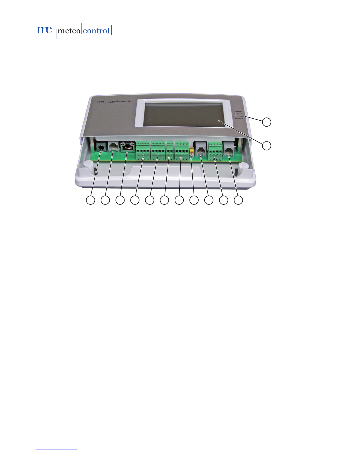
3Overview of the device
3.1 Front view
1
2
3
45
6789
10
11
12
13
Fig. 1: Overview of the device (cover over the connections opened)
(1) Status LED
(2) Touch screen
(3) RS485 interface, RJ12 socket
(4) RS485 interface, screw-clamp terminals
(5) RS485 / 422 combined interface, RJ12 socket
(6) RS485 / 422 changeover switch for combined interface
(7) RS485 / 422 combined interface, screw-clamp terminals
(8) Digital output, screw-clamp terminals
(9) Analog inputs, screw-clamp terminals
(10) Digital inputs, screw-clamp terminals
(11) Ethernet, RJ45 socket
(12) Telephone (PSTN), RJ12 socket
(13) Power supply, socket for plug-in power supply unit
For further information about LEDs and touch screen →Chapter 3.3.

WEB'log Comfort 110621 - en 7/53
3.2 Operator control elements
The data logger is equipped with a touch-sensitive screen (touch screen).
Fig. 2: Touch screen
Symbol Meaning
Go to Diagrams menu
Go to Time selection (Day, Month, Year) menu
Go to Settings menu
Go to System settings menu
Go to Inverter menu
Go to Internet menu
Operator mode display: Administrator
Go to Overview menu
Local alarm active (red background)
Messages (blue background)

8/53 WEB'log Comfort 110621 - en
Delete messages
Go to Provider overview menu
Cursor left or time window minus 1 hour
Cursor right or time window plus 1 hour
Data recording stopped
Data recording started
Increase time scale
Reduce time scale
Reject operator input, return to higher-level menu
Confirm operator input, return to higher-level menu
Option selected (green)
Option not selected (gray)

WEB'log Comfort 110621 - en 9/53
3.3 Status LED
Text LED Meaning
Green: Device is powered
Green: Device is in the start phase
power
Off: Power supply fault
Green: System loaded successfully, normal operation
status
Off: System booting
Yellow: Connection established
Yellow: Attempting to establish a connection
connect
Off: No connection to PSTN modem
Red: Alarm signal at configured output DO1
Red: Fault detected *
alarm
Off: Normal operation
* The Alarm LED flashes in the following cases:
System alarm, measured value alarm, status alarm
Inverter alarm state detected
Inverter Ini file missing
Inverter failure
10/53 WEB'log Comfort 110621 - en
3.4 Standard scope of supply
WEB’log Comfort data logger
24 V DC plug-in power supply unit
Ethernet patch cable
Telephone connecting cable (analog)
Operating Instructions
Drilling template
CD
Drivers (on CF card in device)
Touch pen
Mounting kit (plugs, screws)
Connect cable
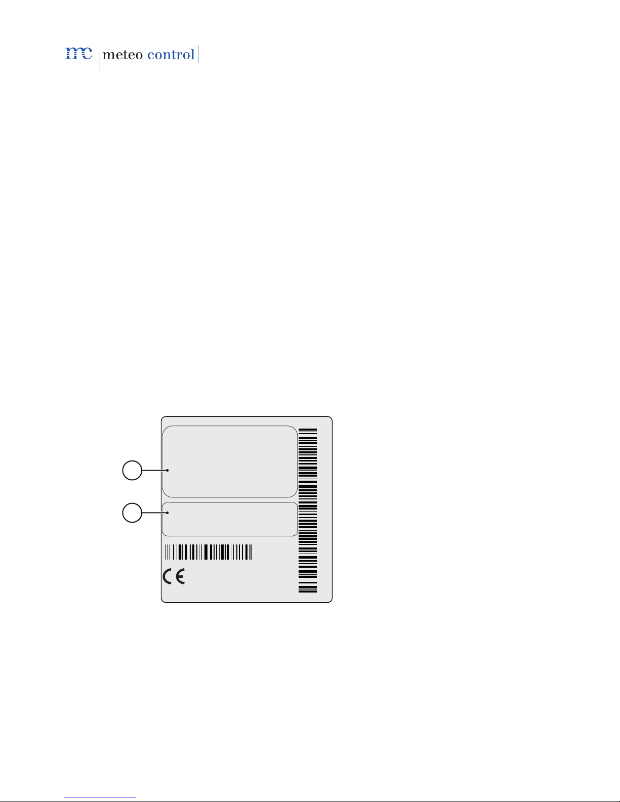
3.5 Rating plate
The rating plate for identification of the device is attached to the back of the
device.
Type
Item No.
YOM
421160 2610 001
Analog
421160 2610 001
2010
Monitoring System
WEB'log Comfort
421.160
MADE IN GERMANY
2
1
Fig. 3: Rating plate
(1) Device type and variant
(2) Modem type, serial number and year of manufacture
Note: Note item number from rating plate for subsequent configuration of
the device.
WEB'log Comfort 110621 - en 11/53
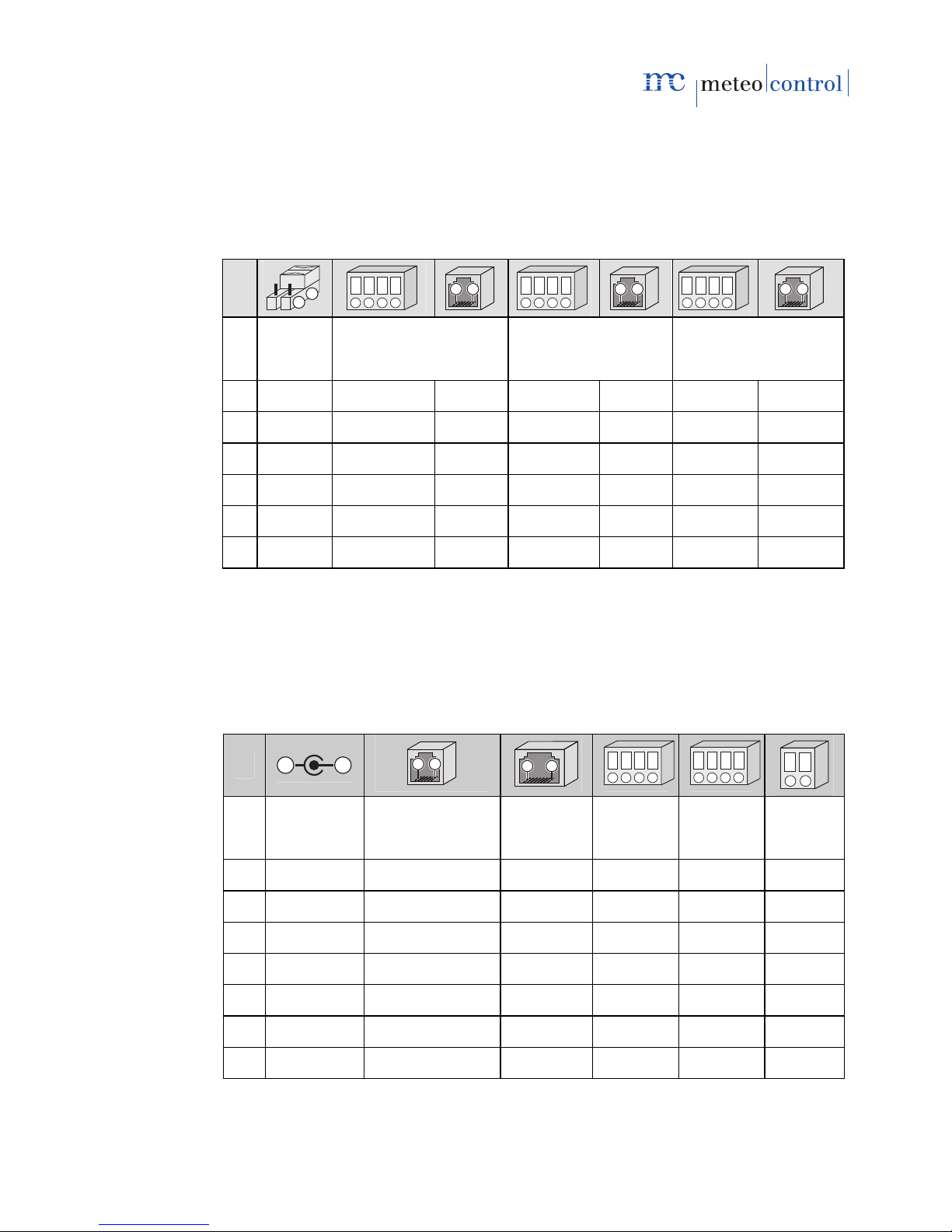
3.6 Assignment of connections
All interfaces are accessible once the plastic cover on the front plate of the
device has been opened.
3.6.1 RS485 / RS422 interfaces
Pin
1
2
1 2 3 4
6 1
1 2 3 4
6 1
1 2 3 4
6 1
Change-
over
switch
Combined interface,
RS485 mode
Combined interface,
RS422 mode
Interface RS485
1 RS485* -- -- RX+ -- +24 V DC +24 V DC
2 RS422 -- RS485 A RX- TX+ RS485 A RS485 A
3 -- RS485 A -- TX+ RX+ RS485 B --
4 -- RS485 B RS485 B TX- TX- GND RS485 B
5 -- -- -- -- RX- -- --
6 -- -- GND -- GND -- GND
Note: The combined interface is not suitable for supplying power to
devices via the RS485 bus (e.g. RS485 hub).
For RS485, always use right-hand interface.
* Factory setting
3.6.2 Other interfaces
Pin
2
1
6 1
81
1 2 3 4 1 2 3 4
12
Plug-in
power
supply unit
PSTN (internal
analog modem)
Ethernet Digital
inputs
Analog
inputs
Digital
output
1 GND -- TX+ DI 1 AI 1 DO Pos
2 +24 V DC a2 (out) TX- GND GND DO Neg
3 -- a1 (in) RX+ DI 2 AI 2
4 -- b1 (in) -- GND GND
5 -- b2 (out) -- -- --
6 -- -- RX- -- --
7,8 -- -- -- -- --
12/53 WEB'log Comfort 110621 - en
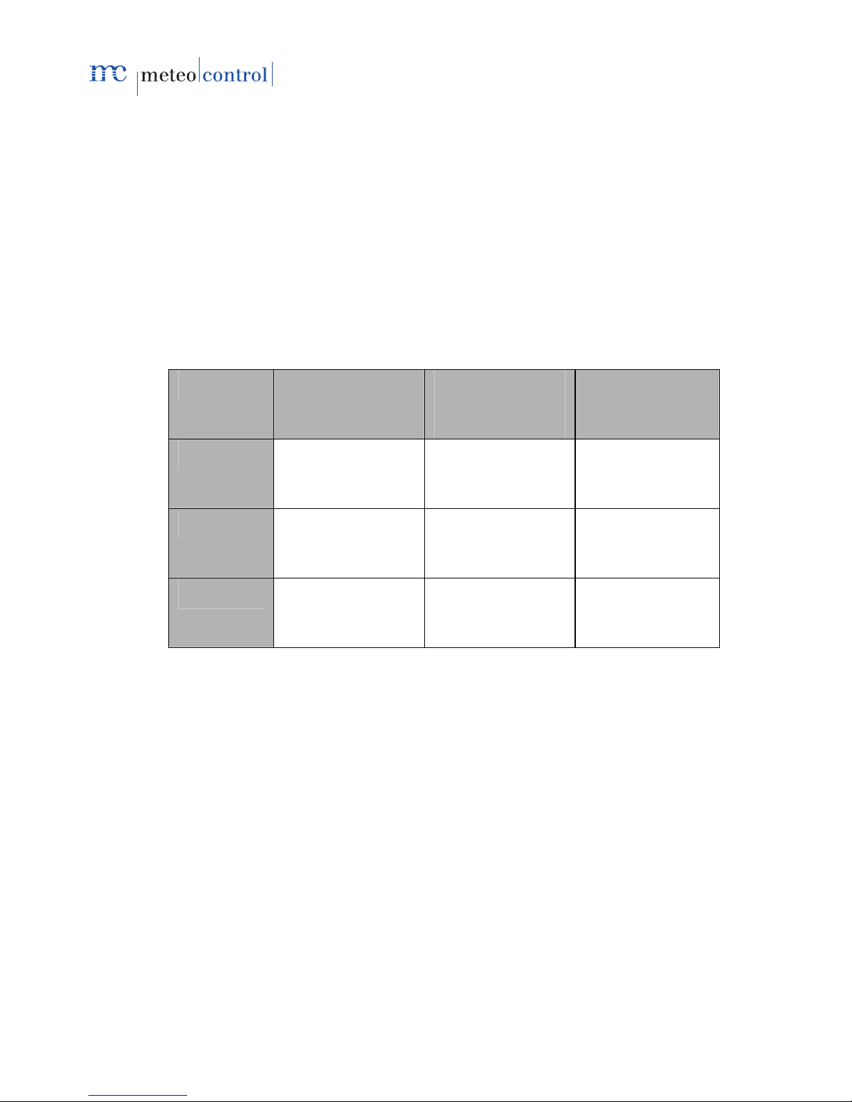
3.7 Default settings
Default setting for the Ethernet connection: DHCP
A manual network configuration is only necessary if no DHCP server is
present.
IP address 192.168.30.40
Subnet mask 255.255.255.0
Gateway 0.0.0.0
Default setting for the modem connection:
IP address 192.168.200.1
Remote IP 192.168.200.51
Subnet mask 255.255.255.255
Direct portal
communication
Sending alarm
messages, daily
files
Time
synchronization
Protocol http smtp (e-mail) SNTP
or
TIME
Port 80,
alternatively 8572
25 SNTP: 123
or
TIME: 37
IP address 213.179.128.168
and
213.179.128.183
213.179.128.176 TIME:
132.163.4.102

WEB'log Comfort 110621 - en 13/53
4Installation
4.1 Safety instructions for installation
Note
Damage due to incorrectly connected cables!
If cables are connected incorrectly, this can damage or destroy the
measuring inputs and the device.
–Connect cables only to the correct locations.
–Ensure the correct polarity of the cables being connected.
Note
Damage due to overvoltage!
Overvoltage or voltage peaks can damage or destroy the device.
–Protect the power supply against overvoltage.
Note
Damage due to overvoltage!
If voltages of more than 10 V DC are applied to the analog inputs, or if
currents of more than 20 mA flow, this can destroy the affected
measuring inputs.
–Ensure that only voltages of up to 10 V DC are applied and only
currents of up to 20 mA flow.
Note
Damage due to incorrect supply voltage!
If there is a voltage higher or lower than 24 V DC at the input for the
supply voltage, the device may be damaged or destroyed.
–Only use the original plug-in power supply unit.
–Only supply the plug-in power supply unit with voltage from the
public grid (no isolated operation).

14/53 WEB'log Comfort 110621 - en
4.2 Cables and wiring
Cable types
Bus cabling (inverters)
Data cable RS485,
twisted and shielded: Li2YCYv (TP) 2×2×0.5 mm21)
Network cable: CAT 7
Sensors (irradiance sensor, temperature sensor)
Sensor cable: LiYCY 2×2×0.5 mm2
Meters (energy meters)
Telephone cable: J-Y(ST)Y 2×0.6 mm2
Ethernet network
Network cable: CAT 5e / CAT 6 / CAT 7
Maximum permissible cable lengths:
Bus cabling (data cable RS485) 1200 m 2) 3)
Sensors 100 m
Meters 200 m
Ethernet network 100 m
3)
“Connect cable” option
We offer a pre-assembled data cable (Connect cable) for connecting the
WEB'log and the first device (inverter).
1) We recommend using the cable type UNITRONIC®Li2YCYv (TP)
manufactured by Lapp Kabel, or an equivalent cable type.
This cable is suitable for direct installation in soil.
2) For longer cable lengths, repeaters must be used.
3) A hub is necessary if a number of separate cables of this length are used.

WEB'log Comfort 110621 - en 15/53
4.3 Installation
The device is intended for wall mounting.
1. Note the ITEM number from the rating plate on the rear for subsequent
configuration.
2. Remove cover over the connections (1).
3. Insert two screws (6) 164 mm apart into the wall (use drilling template
supplied).
4. Mount the device so that the heads of the screws are located in the slots.
5. Push the device down a short way and check that it is seated correctly.
6. Tighten the two screws until the device is securely seated.
1
2
3
4
6
5
Fig. 4: Wall mounting, side view
(1) Remove cover (4) Lift device off
(2) Device (5) Wall
(3) Mount device (6) Fastening screws
4.4 Removal
1. Loosen the two fastening screws.
2. Push device upwards and remove from the screws.

16/53 WEB'log Comfort 110621 - en
4.5 Interfaces
PSTN connection
1. Test the PSTN telephone connection for outgoing and incoming calls (e.g.
provider number; if necessary, include external call prefix and ensure
there are no dialing restrictions). Set the telephone system as described
in the manufacturer’s instructions.
2. Connect the device and the telephone connection with the supplied cable.
If the cable needs to be extended, ensure secure contact and correct
polarity.
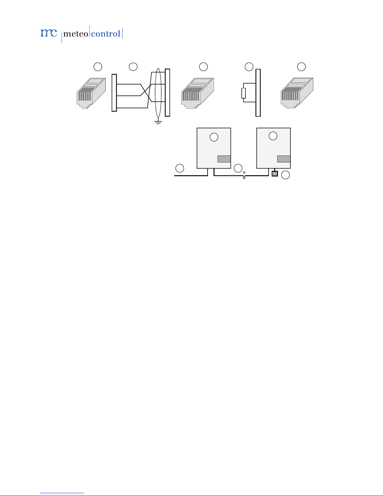
Ethernet connection
Direct connection from data logger and PC / laptop via crossed network
cable (crossover).
DC
PSTN
Ether DI AI DA
RS485 RS485 RS485
RS422 RS485
RS422
3
2
1
Fig. 5: Crossed network cable
(1) Data logger (3) Computer / laptop
(2) Crossed network cable
Note: The crossed network cable is not part of the scope of supply.
Connection to a switch / hub via an uncrossed network cable.
DC
PSTN
Ether DI AI DA
RS485 RS485 RS485
RS422 RS485
RS422
3
2
1
2
4 4
Fig. 6: Uncrossed network cable
(1) Data logger (3) Hub / switch
(2) Uncrossed network cable (4) Computer / laptop
Note: The hub/switch is not part of the scope of supply.

WEB'log Comfort 110621 - en 17/53
4.5.1 Analog input
The analog inputs can be configured as:
- Voltage input (DC): 0...10 V
- Current input 0...20 mA
- Resistance measurement input for a PT1000 two-wire measurement
DC
PSTN
Ether DI AI DA
RS485 RS485 RS485
RS422 RS485
RS422
3 4
2
1
1
Si-12TC
+24 V
GND
Fig. 7: Example of irradiance sensor Si-12TC
(1) Irradiance (orange) (3) GND (black)
(2) + 24 V DC (red) (4) PE shield (black)
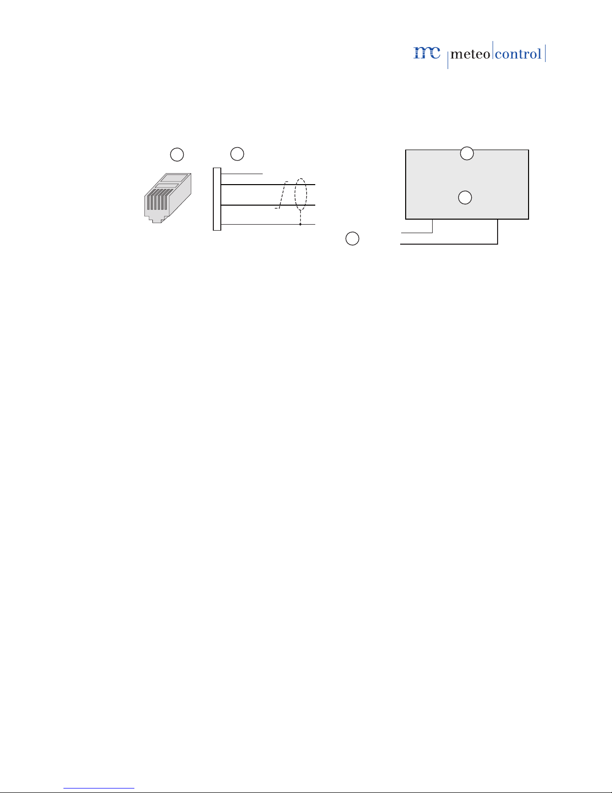
4.5.2 Digital input
The digital inputs are pulse inputs according to DIN43864 (S0) and can be
configured as:
- Counter input
- Status input
DC
PSTN
Ether DI AI DA
RS485 RS485 RS485
RS422 RS485
RS422
2121
1234
21 20
+
-
21 20
+
-
Fig. 8: Example of energy meter
(1) S0 interface, minus (21) (2) S0 interface, plus (20)
Note: For further information about configuration, see Appendix.

18/53 WEB'log Comfort 110621 - en
Power supply
For power supply, use the plug-in power supply unit supplied.
DC
PSTN
Ether DI AI DA
RS485 RS485 RS485
RS422 RS485
RS422
2
1
12
Fig. 9: Power supply
(1) Flexible connecting cable (2) 24V DC plug-in power
supply unit
Note: Only supply the plug-in power supply unit with voltage from the
230 V public grid. Do not power from inverter in isolated operation!
4.6 Bus communication
For communication with inverters, the WEB’log must be equipped with the
appropriate driver.
Note: The required driver is installed by the manufacturer before shipment.
For inverters, only the information required for connection is given.
For further information →Inverter documentation.
Observe the maximum permissible number of devices
Connect the WEB'log to the first device with the data cable or Connect
cable
The order of the bus devices is unimportant
The use of a repeater is necessary for long cable lengths.
As a rule, no operating voltage may be connected to the communication
interfaces of inverters.
The shield of the bus cable must be grounded at one end of the
connection only.
When routing the bus cabling, ensure as great a distance as possible
from AC cables.
To prevent reflections, the bus must always be terminated with a parallel
terminator.
WEB'log Comfort 110621 - en 19/53
4.6.1 General connection diagram
If the connection of the applicable inverter type is not described in the
following sections, then the general connection diagram must be used.
Observe any additional information in the manufacturer’s documentation!
12
RS485 A
RS485 B
RS485 B
RS485 A
1
2
3
4
5
6
GND
+24V
654321
RS485 A
RS485 +
+TR
T+
RS485 B
RS485 -
-TR
T-
3
4
5
Fig. 10: General connection diagram
(1) RJ12 connector (WEB'log), RS485 (4) Inverter
(2) Signal names (5) Possible connection names
(3) Bus cable to the WEB'log
Signal wires RS485 A and RS485 B must not be interchanged
A twisted and shielded wire pair must be used for the bus cable
Terminate the RS485 bus after the last device
(using a resistor, switch, jumper, etc., depending on type of device)
20/53 WEB'log Comfort 110621 - en
4.6.2 Danfoss inverter
654321 543876 21
RS485 A
RS485 B
GND
1
2
3
4
5
6
1
2
3
4
5
6
7
8
543876 21
1
2
3
4
5
6
7
8
123
9
10
4 5
67
8
120 Ω
Fig. 11: Danfoss inverter with Connect Danfoss
(1) RJ12 connector (WEB'log), RS485 (6) First and subsequent inverters
(2) PIN assignment (Connect cable) (7) Last inverter
(3) RJ45 connector (inverter) (8) Connect Danfoss
(4) Pin assignment, terminator (9) Ethernet patch cable
(5) RJ45 terminator (10) Terminator for last inverter
Maximum of 10 inverters per device.
Connect the cable shield to the ground terminal at the WEB'log end
Set the inverter bus address (see inverter documentation)
This manual suits for next models
1
Table of contents
Popular Weather Station manuals by other brands

Hyundai
Hyundai WSC 2180 instruction manual

La Crosse Technology
La Crosse Technology WS-9625U-IT instruction manual

Explore Scientific
Explore Scientific WSH5001 instruction manual

La Crosse Technology
La Crosse Technology WS-3512 Operation manual

La Crosse Technology
La Crosse Technology 308-805 Quick manual

La Crosse Technology
La Crosse Technology WS-7136U instruction manual

Ambient Weather
Ambient Weather WS-YG302 user manual

Oregon Scientific
Oregon Scientific BAR112HGLA user manual

FuehlerSysteme
FuehlerSysteme Compact WS3/O Instructions for use

TFA
TFA 35.1133 instruction manual

Ambient Weather
Ambient Weather WS-1500-IP user manual

Pessl Instruments
Pessl Instruments uMETOS NB-IoT user manual


