FuehlerSysteme Compact WS3/O User manual

1 / 34 ba_7-1-120/11E/0318
Instructions for Use
Weather Station Compact
FS6003

2 / 34 ba_7-1-120/11E/0318
Safety Instructions
•Before operating with or at the device/product, read through the operating instructions.
This manual contains instructions which should be followed on mounting, start-up, and operation.
A non-observance might cause:
- failure of important functions
- endangering of persons by electrical or mechanical effect
- damages to objects
•Mounting, electrical connection and wiring of the device/product must be carried out only by a qualified
technician who is familiar with and observes the engineering regulations, provisions and standards applicable in
each case.
•Repairs and maintenance may only be carried out by trained staff or the manufacturer.
Only components and spare parts supplied and/or recommended by the manufacturer should be used for
repairs.
•Electrical devices/products must be mounted and wired in zero potential state only.
•The manufacturer guarantees proper functioning of the device/products provided that no modifications have
been made to the mechanics, electronics or software, and that the following points are observed:
•All information, warnings and instructions for use included in these operating instructions must be taken into
account and observed as this is essential to ensure trouble-free operation and a safe condition of the measuring
system / device / product.
•The device / product is designed for a specific application as described in these operating instructions.
•The device / product should be operated with the accessories and consumables supplied and/or recommended
by the manufacturer.
•Recommendation: As it is possible that each measuring system / device / product under certain conditions, and
in rare cases, may also output erroneous measuring values, it is recommended to use redundant systems with
plausibility checks with security-relevant applications.
Environment
•Products governed by the provisions of "ElektroG" (German Electrical and Electronic
Equipment Act) will be taken back and will be recycled or environmentally compatible
disposed. We are prepared to take back all products concerned free of charge if returned to us
by our customers carriage-paid.
•Make sure you retain packaging for storage or transport of products. Should packaging
however no longer be required, arrange for recycling as the packaging materials are designed
to be recycled.
Documentation
•© Copyright FuehlerSysteme eNET International GmbH, Nuremberg / Germany
•Although this operating instruction has been drawn up with due care, FuehlerSysteme eNET International
GmbH can accept no liability whatsoever for any technical and typographical errors or omissions in this
document that might remain.
•We can accept no liability whatsoever for any losses arising from the information contained in this document.
•Subject to modification in terms of content.
•The device / product should not be passed on without the/these operating instructions.

3 / 34 ba_7-1-120/11E/0318
Contents
1Device version .......................................................................................................................... 5
2Application................................................................................................................................ 5
3Structure / Mode of operation.................................................................................................... 6
4Installation of COMPACT WS3/O Weather Station ................................................................... 8
4.1 Selection of installation site................................................................................................. 8
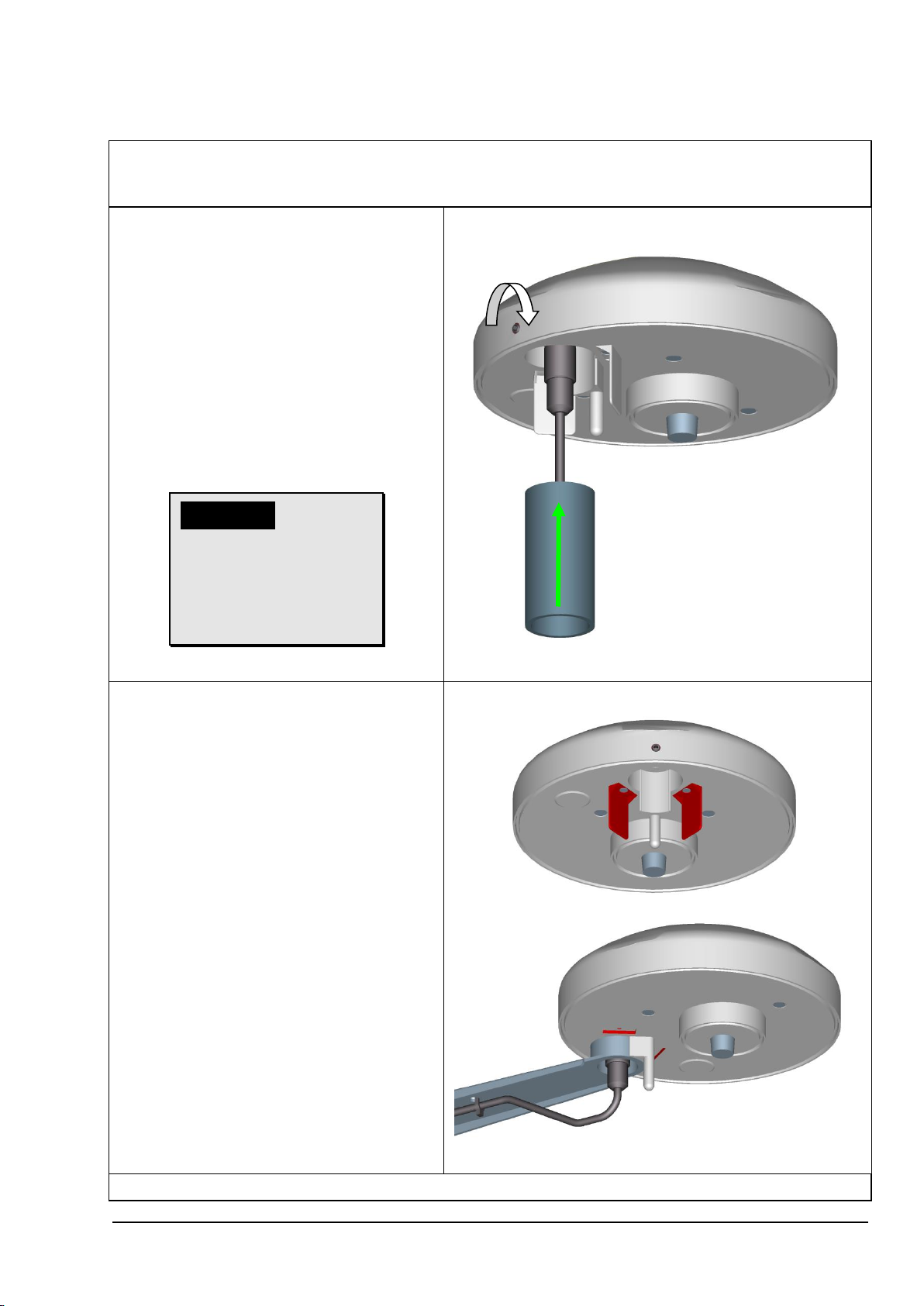
4.2 Mechanical installation........................................................................................................ 9
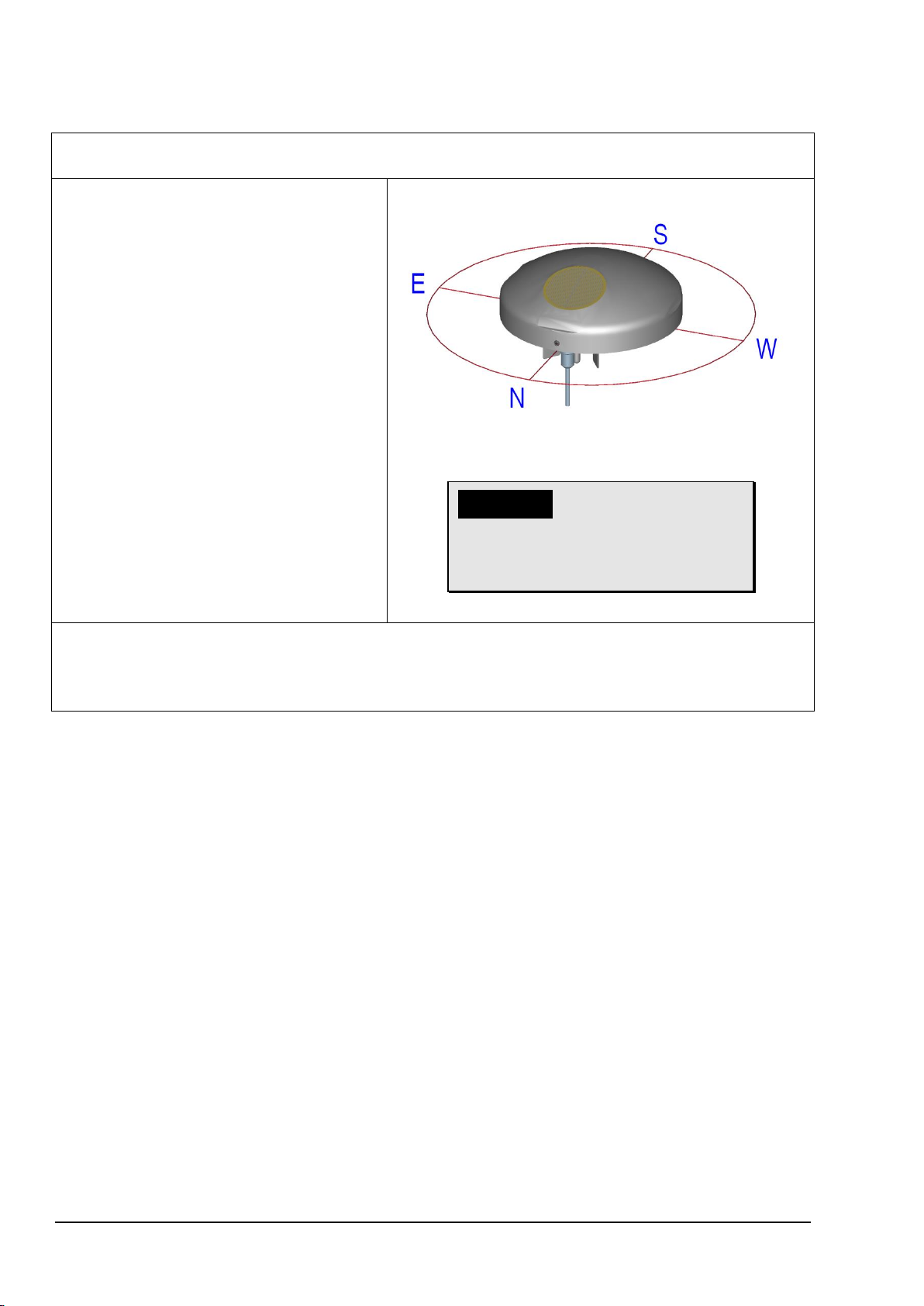
4.2.1 Alignment to north...................................................................................................... 10
4.3 Electrical installation......................................................................................................... 11
4.3.1 Cable, cable preparation, connector installation......................................................... 11
4.3.2 Diagram of connections.............................................................................................. 12
4.3.3 Connection using cable ............................................................................................. 12
5Maintenance ........................................................................................................................... 13
6Interface.................................................................................................................................. 14
6.1 Command interpreter INTERNER BUS..........................Fehler! Textmarke nicht definiert.
6.1.1 Data telegrams........................................................Fehler! Textmarke nicht definiert.
6.2 Command interpreter MODBUS RTU............................................................................... 14
6.2.1 Measuring values (Input Register).............................................................................. 15
6.2.2 Commands (Holding Register) ................................................................................... 19
6.3 Commands and description.............................................................................................. 20
6.3.1 Command AI.............................................................................................................. 20
6.3.2 Command BR............................................................................................................. 22
6.3.3 Command CI...........................................................Fehler! Textmarke nicht definiert.
6.3.4 Command DC ............................................................................................................ 22
6.3.5 Command DO............................................................................................................ 22
6.3.6 Command FB............................................................................................................. 23
6.3.7 Command HP............................................................................................................. 24
6.3.8 Command ID.............................................................................................................. 24
6.3.9 Command KY............................................................................................................. 24
6.3.10 Command LC.......................................................................................................... 25
6.3.11 Command RS ......................................................................................................... 25
6.3.12 Command SH ......................................................................................................... 26
6.3.13 Command SV.......................................................................................................... 26
6.3.14 Command TR.......................................................................................................... 27
6.3.15 Command TT.......................................................................................................... 27
6.3.16 Command TZ.......................................................................................................... 28
7LED signals............................................................................................................................. 29
8Technical data......................................................................................................................... 30
9Dimension drawing [in mm]..................................................................................................... 33
10 Accessories (optional)............................................................................................................. 34

4 / 34 ba_7-1-120/11E/0318
Tables
Table 1 : Status word .................................................................Fehler! Textmarke nicht definiert.
Table 2 : Measured value telegram............................................Fehler! Textmarke nicht definiert.
Table 3 : Sensor data telegram ..................................................Fehler! Textmarke nicht definiert.
Table 4 : MODBUS Frame .............................................................................................................14
Table 5: MODBUS Exceptions .......................................................................................................15
Table 6 : MODBUS Input Register..................................................................................................18
Table 7 : List of commands ............................................................................................................20
Figures
Figure 1 : LEDs..............................................................................................................................29
Figure 2 : Spectrum of brightness sensors.....................................................................................32
Figure 3 : Directional characteristics of brightness sensors............................................................32
Figure 4 : Spectrum for global irradiance sensor ............................................................................33
Instructions for use
These instructions for use describe all application and adjustment options for the device.
These detailed instructions allow users to modify the factory settings to their needs via the serial
interface of the Weather Station Compact WS3/O.
Scope of supply
1 Weather Station Compact WS3/O.
1 Copy of the instructions for uses.

5 / 34 ba_7-1-120/11E/0318
1 Device version
Designation
Order No.
Output
terminal
Data format
Operating voltage
WETTERSTATION
COMPACT WS3/O
WS3/O-MB
1 x RS485
Data in binary format
(command interpreter:
MODBUS RTU)
18...30V DC
18...28V AC
2 Application
The WEATHER STATION COMPACT WS3/O is designed for use in building services automation
systems (e.g. shade protection control). The WS3/O features the following measured variables:
•Wind speed.
•Wind direction.
•4 x brightness (north / east / south / west).
•Twilight.
•Global irradiance.
•Precipitation.
•Air temperature.
•Absolute air pressure.
•Relative air pressure.
•Time / date.
•Geostationary data (local altitude, longitude and latitude).
•Position of the sun (elevation / azimuth).
•Relative air humidity.
•Absolute humidity.
•Dew-point temperature.
•Inside temperature of housing.
The interface to the device is digital and consists of an RS485 interface in half-duplex mode.
Together with ID-based communications the interface allows the Weather Station to be operated in
a bus.

6 / 34 ba_7-1-120/11E/0318
3 Structure / Mode of operation
Wind speed / wind direction:
Wind measurement is based on the hot wire principle. The underside of the housing is equipped
with a heated cylindrical sensor. A PID controller adjusts the temperature of the cylinder to a
temperature that is constantly increased in relation to the environment. The supplied heat energy is
a measure of wind speed.
The metal cylinder contains four temperature-measuring resistors. These resistors are thermally
coupled with the cylinder and positioned according to the 4 points of the compass. When an
incident flow affects the cylinder as a function of the wind direction, this is accompanied by a
temperature gradient which is registered by the measuring resistors. The relationships between the
4 temperature values are used to calculate the wind direction.
In case the wind direction cannot be determined because the wind velocity is 0m/s, the value is set
to 0. Wind from the north is displayed with 360°.
Brightness:
The brightness measurement is carried out via 4 Silicium photo sensors, which are aligned to the
4 cardinal directions in the mean elevation angle (40°).
Twilight:
Twilight means the light diffusion in the atmosphere, which arises with the smooth transition
between day and night before the beginning or after the end of day.
i.e., the solar disc is not visible.
The twilight is direction-independent.
It is calculated from the sum of the 4 measuring values of the direction-independent brightness
sensors.
A change to the mean value from the 4 brightness values is possible by command.
Global irradiance:
A silicon PIN photodiode is used to measure global irradiance. The sensor is positioned horizontally
and registers the diurnal values of the solar irradiation intensity.
Precipitation:
The detection of precipitation is based on capacitance measurement, i.e. the capacity of the sensor
surface varies when wet. The sensor is installed in the housing cover. An integrated heating system
adjusts the sensor area to an overtemperature in relation to the ambient temperature. This
overtemperature (approx. 2K) prevents bedewing of the sensor surface. The thermal output is
increased with precipitation. This accelerates drying of the sensor, allowing the time at which
precipitation ended to be identified more accurately.

7 / 34 ba_7-1-120/11E/0318
Air temperature:
A PT1000 measuring resistor is used to measure the air temperature. The sensor is mounted on a
flexible printed board and positioned in the lower section of the housing.
Air pressure:
Absolute air pressure is measured with a piezoresistive MEMS sensor.
To make a meaningful comparison between air pressure values simultaneously measured at
different locations, they need to be converted to a common datum (height above sea level). The
calculation is referred to the height above sea level (QNH) according to the international altitude
formula (DIN ISO2533).
Ph= air pressure at local altitude
Pb= air pressure at height above sea level
= -0065K/m
gn= 9.80665m/s2
R = 287.05287m2/K/s2
Tb= 288.15K
The station height, required for the calculation, can be entered manually by the Command SH, or
can be determined automatically by GPS.
If you want to achieve an accuracy of 0.1hPa, referred to sea level, the local altitude (altitude of the
baro transmitter) must be given up to an accuracy of 0.8m.
Time / date and geostationary data:
The Weather Station has a GPS receiver with a built-in RTC. This allows it to receive the position of
the Weather Station (degree of longitude/latitude, local altitude) time (UTC) and date. The GPS
receiver does not need alignment.
The built-in RTC (Real Time Clock) is buffered with a backup capacitor and retains its data without
a voltage supply for a period of minimum 3 days.
Position of the sun (elevation / azimuth):
On the basis of the GPS data the current sun position is calculated every second.
R
g
T
b
n
bhphp
)1()(

8 / 34 ba_7-1-120/11E/0318
Humidity measurement:
A built-in hygro-thermosensor is used to measure humidity levels. The sensor has a small air
exchange volume thanks to its compact design and responds to changes in humidity in seconds.
A software module uses the relative humidity and air temperature to calculate absolute humidity
and the dew-point temperature.
Inside temperature of housing:
A silicon temperature sensor measures the temperature inside the housing.
GPS-Receiver:
The weather station has a GPS receiver with integrated RTC (Real Time Clock) for receiving the
position of the weather station, and time + date (UTC).
An alignment of the GPS receiver is not necessary.
The integrated RTC is buffered for a period of 3 days.
General information:
After activation of the WS3/O the first satellite data are available after approx. 2.5min.
When receiving the signals from one satellite: time with an accuracy of < 1µs.
When receiving the signals from three satellites: position with an accuracy of < 20m
When receiving the signals from four satellites: altitude, referred to the WGS84-
ellipsoid, with an accuracy < 30m
4 Installation of COMPACT WS3/O Weather Station
Please note:
The working position of the COMPACT WS3/O Weather Station
is horizontal (plug connection underneath).
During installation, de-installation, transport or maintenance of
the COMPACT WS3/O Weather Station make sure that no water
gets into the device and connector.
4.1 Selection of installation site
An exposed position should be selected for this site. Measurement properties should not be
influenced by light reflections, cast shadows or the device being positioned in the lee of the wind.
Protection against lightning and overvoltages should also be provided by the customer.

9 / 34 ba_7-1-120/11E/0318
4.2 Mechanical installation
The intended installation of the Weather Station WS3/O requires the use of a pipe socket / pipe
with an outside diameter of ≤25mm. The inside diameter must be ≥19mm to admit the
connector and cable.
Tool:
Hexagon socket wrench SW2mm
(socket wrench).
Procedure:
1. Push cable/plug connection
through the bore hole of the mast,
tube, bracket etc.
2. Put WS3/O on mast, tube.
3. Align WS3/O to “north”.
(Procedure see chapter 4.2.1).
4. Secure WS3/O by the M4-
hexagon socket screw.
Attention:
The hexagon
socket screw
is to be
tightened by
max. 0.6Nm.
When using the
mounting angel (see chapter
accessories) the guide angles must be
removed, see fig.
The mounting angle is not included in
delivery.
Remark: Tube and mounting angle are not included in delivery.

10 / 34 ba_7-1-120/11E/0318
4.2.1 Alignment to north
For the exact determination of wind- and brightness direction the WEATHER STATION COMPACT
WS3/O must be mounted in north alignment (geographic north).
The hexagon socket screw serves as
north marking (N)
Tool:
Hexagon socket wrench SW 2mm
(socket wrench).
Procedure:
1. Detect a prominent object in the
surrounding area (tree, building
etc.) in north direction by means of
a compass.
2. Via the north marking (N) and an
imaginary north-south axis the
weather station is to be located on
the prominent object.
3. Align weather station.
The north marking must indicate to
the geographic north.
4. In case of match the weather
station is to be secured by an M4-
hexagon socket screw.
Attention:
The hexagon socket
screw is to be tightened
by max. 0.6Nm.
Remark:
With the north alignment by means of a compass, the local variation (deviation in direction of a
compass needle from the true north direction) by interfering magnetic fields, and magnetic field
influences by hardware and electric cable are to be considered.

11 / 34 ba_7-1-120/11E/0318
4.3 Electrical installation
The COMPACT WS3/O Weather Station is equipped with a 7-pin plug for electrical connection. A
cable socket (mating connector) is included in the scope of supply.
4.3.1 Cable, cable preparation, connector installation
The cable to be used for connection should have the following properties:
5 cores, core cross-section max. 0.14mm², cable diameter max. 5.0mm, resistant to ultraviolet rays,
overall shielding.
Note:
A prepared connecting cable is available for the COMPACT WS3/O Weather
Station as an optional accessory.
Cable socket, type: Binder, series 711

12 / 34 ba_7-1-120/11E/0318
4.3.2 Diagram of connections
Order No.
WS3/O-MB
View of
solder terminal
of mating connector
(cable socket)
2
4
6
3
5
1
7
* With long transmission paths connection to the GND of data acquisition may reduce their susceptibility to
interference.
Important:
* Do not connect DATA_GND to the supply voltage-GND.
4.3.3 Connection using cable
PIN
Core colour
Function
1
WHITE
NC
2
BROWN
* DATA _ GND
3
GREEN
DATA +
4
YELLOW
DATA -
5
GREY
NC
6
PINK
+ power 18...30V DC / 18...28V AC
7
BLUE
- power 18...30V DC / 18...28V AC
* With long transmission paths connection to the GND of data acquisition may reduce their susceptibility to
interference.
Important:
* Do not connect DATA_GND to the supply voltage-GND.
7 pol. Binder Steckverb. / Plug
7
Erde
Versorgung
DATA +
Earth
* DATA _ GND
Schirm / Shield
Power
18 ... 30 VDC
18 ... 28 VAC
DATA -
~~
NC NC
123456

13 / 34 ba_7-1-120/11E/0318
5 Maintenance
As the device does not have any moving parts, i.e. is not subject to wear during operation, only
minimal servicing is required.
Depending on the location the instrument might pollute. The cleaning should be carried out by
means of water and a soft cloth. Aggressive cleaning agents must not be used.
Please note:
During storage, installation, de-installation, transport or
maintenance of the COMPACT WS3/O Weather Station make
sure that no water gets into the device or connector.

14 / 34 ba_7-1-120/11E/0318
6 Interface
The interface to the Weather Station consists of a RS485 link (half-duplex mode), with the following
data format:
•9600baud (the baud rate can be selected with the Command BR).
•8data bits.
•No parity.
•1stop bit.
•Data in binary format (command interpreter: MODBUS RTU).
The behavior (configuration) of the Weather Station can be changed using the available commands
(see Commands and description).
When the Weather Station starts up, the character string "Weather Station", software version,
hardware version and serial number is output:
Weather Station
v03.04
508990 v11-11
12030123
6.1 Command interpreter MODBUS RTU
Once the command interpreter is selected the transmitted bytes are interpreted according to the
MODBUS specification (http://www.modbus.org/). Here, the weather station WS3/O is representing
a MODBUS Slave.
The data transmission is carried out in packages, so-called frames, of maximum 256 bytes. Each
package contains a 16bit CRC checksum (initial value: 0xffff).
Slave-Address
Function code
Data
CRC
1byte
1byte
0...252byte(s)
2bytes
CRC low-byte
CRC high-byte
Table 1 : MODBUS Frame
The following MODBUS functions are supported:
- 0x04 (Read Input Register).
- 0x03 (Read Holding Registers).
- 0x06 (Write Single Register).
- 0x10 (Write Multiple Registers).
The weather station WS3/O supports a write access for the slave-address 0 (“Broadcast”).
All received MODBUS request are checked for validity before carrying out. In error case the
weather station responds with one of the following exceptions (MODBUS Exception Responses).

15 / 34 ba_7-1-120/11E/0318
Code
Name
Signification
0x01
ILLEGAL FUNCTION
The function code in the request is not allowed for the
register address.
0x02
ILLEGAL DATA ADDRESS
The register address in the request is not valid.
0x03
ILLEGAL DATA VALUE
The stated data in the request are not allowed.
Table 2: MODBUS Exceptions
6.1.1 Measuring values (Input Register)
All measuring values of the weather station WS3/O consume 32Bit, i.e. 2 MODBUS register
addresses. The following table shows the allocation of measuring value to register address, while
the measuring values are sorted as follows:
- By measuring value type (30001 to 34999).
- In unbroken sequence (35001 to 39999).
Register
address
Parameter Name
Unit
Multiplicator
Explanation
Data
type
30001
Wind speed
m/s
10
value / 10
(1 decimal place, e.g.
101=10.1m/s)
U32
30003
Mean value
Wind speed
m/s
10
value / 10
(1 decimal place, e.g..
101=10.1m/s)
U32
30201
Wind direction
°
10
value/ 10
(1 decimal place, e.g.
1010=101.0°)
U32
30203
Mean value
Wind direction
°
10
value / 10
(1 decimal place, e.g.
1010=101.0°)
U32
30401
Air temperature
°C
10
value / 10
(1 decimal place, e.g.
255=25.5°C)
S32
30403
Interior temperature of
housing
°C
10
value / 10
(1 decimal place, e.g.
355=35.5°C)
S32
30601
relative humidity
%r.h.
10
value/ 10
(1 decimal place, e.g.
355=35.5°r.F.)
U32
30603
absolute humidity
g/m³
100
value / 100
(2 decimal places, e.g.
923=9.23g/m^3)
U32
30605
Dew point temperature
°C
10
value / 10
(1 decimal place, e.g.
115=11.5°C)
S32
30801
Absolute air pressure
hPa
100
value / 100
(2 decimal places, e.g.
U32

16 / 34 ba_7-1-120/11E/0318
105000=1050.00hPa)
30803
Relative air pressure
relating to NHN
hPa
100
value / 100
(2 decimal places, e.g.
105000=1050.00hPa)
U32
31001
Global radiation
W/m²
10
value / 10
(1 decimal place, e.g
10000=1000.0W/m^2)
S32
31201
Brightness north
kLux
10
value / 10
(1 decimal place, e.g.
1200=120.0kLux)
U32
31203
Brightness east
kLux
10
value / 10
(1 decimal place, e.g.
1200=120.0kLux)
U32
31205
Brightness south
kLux
10
value / 10
(1 decimal place, e.g,
1200=120.0kLux)
U32
31207
Brightness west
kLux
10
value / 10
(1 decimal place, e.g.
1200=120.0kLux)
U32
31209
Twilight
Lux
1
value
(no decimal place, e.g.
500=500Lux)
U32
31401
Precipitation status
1
value
(no decimal place, (0=no
precipitation, 1=precipitation)
U32
34601
Date
1
value
(no decimal place,
JJJJMMTT, e.g.
20121210=10.12.2012)
U32
34603
Time
1
value
(no decimal place,
HHMMSS, e.g. 121035=12:10:35)
U32
34605
Time format
h
1
value
(no decimal place, offset to UTC in
hours, e.g. 60=UTC+1h)
S32
34801
Longitude
°
1000000
value / 1000000
(6 decimal places, e.g. )
S32
34803
Latitude
°
1000000
value/ 1000000
(6 decimal places, e.g. )
S32
34805
Sun position Elevation
°
10
value / 10
(1 decimal place, e.g. 900=90.0°)
S32
34807
Sun position Azimuth
°
10
value / 10
(1 decimal place, e.g. 1800=180.0°
/ 0°=north, 180°=south, clockwise
0…360°)
S32
34809
Height above sea level
m
1
value
(no decimal place, e.g. 240=240m
above sea level)
U32
34811
Sensor status
1
value
(no decimal place, bit coded, dep.
of sensor)
U32
34813
Main loop cycles per 1s
1/s
1
Value
(no decimal place, for ex.
U32

17 / 34 ba_7-1-120/11E/0318
2550=2550 1/s)
34815
Operating time
s
1
Value
(no decimal place, for ex.
255=255s)
U32
34817
Mean value of the height
over MSL, received via
GPS.
m
10
Value
(1 decimal place, e.g.
240=24.0m above MSL)
U32
35001
Wind speed
(30001)1
m/s
10
value / 10
(1 decimal place, e.g.
101=10.1m/s)
U32
35003
Mean value Wind speed
(30003)1
m/s
10
value / 10
(1 decimal place, e.g.
101=10.1m/s)
U32
35005
Wind direction
(30201)1
°
10
value/ 10
(1 decimal place, e.g.
1010=101.0°)
U32
35007
Mean value wind
direction
(30203)1
°
10
value / 10
(1 decimal place, e.g.
1010=101.0°)
U32
35009
Air temperature
(30401)1
°C
10
value / 10
(1 decimal place, e.g. 255=25.5°C)
S32
35011
Interior temperature of
housing
(30403)1
°C
10
Value / 10
(1 decimal place, e.g. 355=35.5°C)
S32
35013
Dew point temperature
(30605)1
°C
10
value/ 10
(1 decimal place, e.g. 115=11.5°C)
S32
35015
Rel. humidity
(30601)1
%r.h.
10
value / 10
(1 decimal place, e.g.
355=35.5°r.h.)
U32
35017
Abs. humidity
(30603)1
g/m^3
100
value / 100
(2 decimal places, e.g.
923=9.23g/m^3)
U32
35019
Absolute air pressure
(30801) 1
hPa
100
value / 100
(2 decimal places, e.g.
105000=1050.00hPa)
U32
35021
Rel. air pressure relating
to sea level (30803) 1
hPa
100
value / 100
(2 decimal places, e.g.
105000=1050.00hPa)
U32
35023
Global radiation
(31001)1
W/m^2
10
value / 10
(1 decimal place, e.g.
10000=1000.0W/m^2)
S32
35025
Brightness north
(31201)1
kLux
10
value / 10
(1 decimal place, e.g.
1200=120.0kLux)
U32
35027
Brightness east
(31203)1
kLux
10
value / 10
(1 decimal place, e.g.
1200=120.0kLux)
U32
35029
Brightness south
(31205)1
kLux
10
value / 10
(1 decimal place, e.g.
1200=120.0kLux)
U32
35031
Brightness west
(31207)1
kLux
10
value / 10
(1 decimal place, e.g.
1200=120.0kLux)
U32
35033
Twilight
(31209)1
Lux
1
value
(no decimal place, e.g.
500=500Lux)
U32
35035
Precipitation status
1
value
(no decimal place, (0=no
U32

18 / 34 ba_7-1-120/11E/0318
(31401)1
precipitation, 1=precipitation)
35037
Date
(34601)1
1
value
(no decimal place,
JJJJMMTT, e.g.
20121210=10.12.2012)
U32
35039
Time
(34603)1
1
value
(no decimal place,
HHMMSS, e.g. 121035=12:10:35)
U32
35041
Time format
(34605)1
h
1
value
(no decimal place, Offset to UTC in
hours, e.g. 60=UTC+1h)
S32
35043
Longitude
(34801)1
°
1000000
value / 1000000
(6 decimal places, e.g. )
S32
35045
Latitude
(34803)1
°
1000000
value / 1000000
(6 decimal place, e.g. )
S32
35047
Sun position Elevation
(34805)1
°
10
value / 10
(1 decimal place, e.g.
900=90.0°)
S32
35049
Sun position Azimuth
(34807)1
°
10
value / 10
(1 decimal place, e.g.
1800=180.0° / 0°=north,
180°=south, clockwise 0…360°)
S32
35051
Height above sea level
(34809)1
m
1
Wert
(no decimal place, e.g.
240=240m above sea level)
U32
35053
Sensor status
(34811) 1
1
value
(no decimal place, bit coded, dep.
of sensor)
U32
35055
Main loop cycles
1/s
1
value
(no decimal place, number cycles
per 1s)
U32
35057
SHT2x temperature
°C
10
value / 10
(1 decimal place, e.g.
255=25.5°C)
S32
35059
NTC temperature
°C
10
value / 10
(1 decimal place, e.g.
255=25.5°C)
S32
35061
Operating time
s
1
Value
(no decimal place, for ex.
24000=24000s since last reset)
U32
35063
Mean value of the height
over MSL (34817)1,
received via GPS.
m
10
Value
(1 decimal place, e.g.
240=24.0m above MSL)
U32
Table 3 : MODBUS Input Register
1: The numbers in parentheses describe the register addresses, which mean the same measuring value. Thus, the wind speed for ex. is
situated at address 30001 and at address 35001.

19 / 34 ba_7-1-120/11E/0318
Remark:
Due to the unbroken sequence of the measuring values,
starting from address 35001, the MODBUS master can read-out
all measuring values by one request!
6.1.2 Commands (Holding Register)
All commands of the weather station WS3/O consume 32Bit, i.e. 2 MODBUS register addresses,
and are representing unsigned integral numbers. The following example shows the changing of the
baud rate to 19200baud.
1. Set password for the user level (KY=234)
Slave
address
Function
code
Starting
address
Number
Registers
Number
byte(s)
Data
CRC
0x01
0x10
0x9C 49
0x00 02
0x04
0x00 00 00 EA
0x4F 7C
CRC
low-
Byte
CRC
high-Byte
2. Set command baud rate to 19200 baud (BR=6)
Slave
address
Function
code
Starting
address
Number
Registers
Number
byte(s)
Data
CRC
0x01
0x10
0x9C 45
0x00 02
0x04
0x00 00 00 06
0x4E A4
CRC
low-
Byte
CRC
high-Byte

20 / 34 ba_7-1-120/11E/0318
6.2 Commands and description
The following table lists the available commands and the associated passwords for read / write:
Command
Initial value
factory
setting
MODBUS
register-
address
Description
Password
Read1/Write2
Command AI
10
40069
Averaging interval for wind speed
and wind direction.
None
User
Command BR
96
40005
Select baud rate.
None
User
Command DC
0
40081
Mode of calculation for twilight.
None
User
Command DO
0
40037
North correction of wind direction.
None
User
Command FB
1
40001
Quick-start mode.
None
User
Command HP
5
40035
Heating capacity anti-condensation
None
User
Command ID
0
(INTERNER
BUS)
1 (MODBUS)
40003
Identification number resp. slave
address.
None
User
Command KY
0
40009
Set key / password.
None
None
Command LC
0
40045
LED control.
None
None
Command RS
-
40029
Reset.
None
User
Command SH
0
40071
Station height.
None
User
Command SV
-
45005
SW-Version.
None
-
Command TR
-
-
Telegram output.
None
None
Command TT
0
-
Automatic telegram output.
None
None
Command TZ
0
40073
Time zone.
None
User
Table 4 : List of commands
1: Command without parameter (used to read selected parameter).
2: Command with parameter (used to write a new parameter).
6.2.1 Command AI
<id>AI<parameter><CR> Averaging interval for wind speed and wind direction
Access: Read / write.
Description: The command AI is used to specify the averaging interval for the wind
speed and wind direction in minutes.
The averaging of the wind velocity is scalar, and the averaging of the
wind direction vectorial.
If the parameter is 0, the averaging is deactivated, and the mean
values correspond to the instantaneous values. Here, the wind
direction is reset (to 0°) during calm (< 0.6m/s).
Wind from the North is displayed with 360°.
Parameter description: AI = 0 averaging disabled
AI = 1 averaging interval = 1 minute
Value range: 0...10
This manual suits for next models
1
Table of contents
Other FuehlerSysteme Weather Station manuals