METER AROYA H210 User manual

AROYA

TABLE OF CONTENTS
1. Introduction .............................................................................................1
2. Operation ..................................................................................................3
2.1 Installation ................................................................................................3
3. System.........................................................................................................6
3.1 Specifications............................................................................................6
3.2 Components ............................................................................................11
3.2.1 Gateway (H210) .............................................................................11
3.2.2 Repeater (H110) and Climate Station (H111)..................................13
3.2.3 Sensor Nose (H321) .......................................................................14
4. Service.......................................................................................................16
4.1 Maintenance ...........................................................................................16
4.2 Repairs ....................................................................................................16
4.3 Troubleshooting.......................................................................................16
4.4 Customer Support ...................................................................................18
4.5 Terms and Conditions ..............................................................................18
APPENDIX A. Compliance Certifications ....................................19
A.1 USA.......................................................................................................... 19
A.2 CANADA .................................................................................................. 21
13862-02
1.2022
i

1. INTRODUCTION
Thank you for choosing the AROYA system from METER Group. Prior to use, verify the sensor
arrived in good condition.
The AROYA system works in a wireless mesh network. A wireless mesh network allows data
and files to be transferred from one device to another through wireless transmission. The
AROYA system components are FCC approved (Class A) and can communicate wirelessly
between each other. The Gateway, Repeater, and Climate Station all use Power over Ethernet
(PoE) that is compliant with IEEE 802.3af PoE standards.
The AROYA Gateway (H210—Figure 6 and Figure 7) sends and receives data transmitted by
the Repeater or Sensor Nose and provides the system with an active connection to the cloud
server where all data is processed and presented to the user.
The AROYA Repeater (H110—Figure 8) functions as a range extender, receiving data from the
Sensor Nose and transmitting data wirelessly to the Gateway.
The AROYA Climate Station (H111—Figure 9) includes a Repeater and an ATMOS14 temperature
and relative humidity (RH) sensor. The ATMOS 14 supports SDI-12 sensor communication to
capture microclimate sensor data. Data collected by the sensor is transmitted wirelessly to
theGateway.
The AROYA Sensor Nose (H321—Figure 10 and Figure 11) has communication components
and an antenna to transmit data to the Repeater or directly to the Gateway if the Sensor
Nose is close enough. The Sensor Nose connects to variety of sensors.
1
AROYA

Switch
Misc other equipment
(e.g., Wi-Fi
®
router)
Modem
Port 8883, Port 8443
Wireless
Sensor
Wireless
Sensor
Wireless
Sensor
Wireless
Sensor
Wireless
Sensor
Wireless
Sensor
Wireless
Sensor
AROYA GatewayLANPoE
*PoE injector (if needed)
AROYA
Repeater
AROYA
Repeater
AROYA
Repeater
AROYA
Climate
Internet
Wireless
Sensor
Wireless
Sensor
AROYA
Climate
AROYA
Climate
AROYA
Climate
AROYA
Climate
Existing Customer Network
AROYA System Configuration
Figure 1 AROYA mesh network
2
INTRODUCTION

2. OPERATION
Please read all instructions before operating the AROYA to ensure it performs to its
fullpotential.
PRECAUTIONS
METER sensors are built to the highest standards, but misuse, improper protection, or
improper installation may damage the sensor and possibly void the manufacturer’s
warranty. Before integrating AROYA into a system, make sure to follow the recommended
installation instructions and have the proper protections in place to safeguard sensors
from damage.
2.1 INSTALLATION
Follow the steps listed in Table1 to set up the Gateway.
Table1 H210 Gateway Installation
Tools Needed Cordless drill
Screw driver
Screws
Preparation Consider the Surroundings
Locate the Gateway in a hallway or office with internet access for PoE.
The site network infrastructure will determine what installation method is
required so the Gateway can communicate with other parts of the system.
If this is not possible, locate the Gateway wherever there is access to
connections required to establish communication.
The Gateway needs to be close enough to the Repeater(s) for the signal from
the Repeater to reach the Gateway.
Verify Internet Connectivity
Log into the AROYA software or mobile app.
Go to the Devices pages.
Select Gateway under All Devices.
A check mark icon indicates the Gateway is connected to the internet.
Mounting METER recommends putting the Gateway on a table or shelf.
Configuration All system configuration work is done at METER before installation occurs at
the customer site.
3
AROYA

Follow the steps listed in Table2 to set up the AROYA Repeater.
Table2 Repeater (H110) Installation
Preparation
Consider the Surroundings
METER recommends installing the Repeater in the hallways about shoulder
height to enhance transmission of data from sensors throughout the facility
back to the Gateway.
Mounting Install the Repeater at approximately shoulder height in a hallway. Use
screws inserted into the mounting bracket to secure to wall.
Configuration All system configuration work is done at METER before installation occurs at
the customer site.
Connecting
Connect Repeater to PoE and Verify
Connect one end of this cable to the Repeater (Figure 8) and the other to the
PoE Router or a PoE injector.
Verify the Repeater is connected to the internet and functional by looking
through the device page in AROYA or looking for a steady blue LED light on
the surface shown in Figure 8.
Follow the steps listed in Table3 to set up the AROYA Climate Station.
Table3 Climate Station (H111) Installation
Tools Needed Grow light hanger (e.g., rope ratchet clip hanger)
Chain, cable, or rope
Preparation
Consider the Surroundings
METER recommends installing the Climate Station in the center of each room
of the greenhouse to facilitate quality communication to the Gateway.
The Climate Station should be in an area where the environment is as
consistent as possible. If a fogger is set up in the center of a room, set up the
Repeater in a location away from the fogger.
Mounting METER recommends installing the Climate Station in the center of the room
just over the canopy using the light hanger pulley provided.
Configuration The Climate Station needs to be assigned to the room that it is installed in.
Connecting
Connect Climate Station to PoE and Verify
Securely hold the cable gland on the Climate Station side, and unscrew the
outer cover from the side that is open. Remove the the cap and grommet.
Follow the steps below, referring to Figure 2.
• Slide the water-tight coupling pieces onto the PoE Ethernet cable in
the following order: cap, blue seal grommet, outer cover.
• Plug the PoE connector into the coupling.
• Screw the outer cover onto the coupling and tighten.
• Slide and push the blue seal grommet into the outer cover flexible prongs.
• Screw the cap onto the outer cover, over the grommet,and tighten (do not
overtighten).
4
OPERATION

Table 3 Climate Station (H111) Installation (continued)
Connecting
(continued)
Cable to
Climate Statio
nCable to
Power over
Ethernet (PoE)
injector adapter
Coupling
Outer
cover
Flexible
prongs
Cap
Blue
seal
grommet
PoE
connector
Climate Station
connector
Figure 2 Water-tight coupling
Verify the Climate Station is connected to the internet and functional by
looking through the devices page in AROYA or looking for a steady blue LED
light on the surface shown in Figure 9.
Follow the steps in Table 4 to set up the AROYA Sensor Nose.
Table4 Sensor Nose (H321) Installation
Tools Needed AROYA Sensor Nose
Preparation
Consider the Surroundings
The TEROS12 needles are inserted into the substrate.
Check Sensor Functionality
Press the function button (Figure 10) until the LED flashes green.
Mounting Insert sensor into slabs or larger substrate types.
Configuration All system configuration work is done at METER before installation occurs
at the customer site.
Connecting
Wake Sensor Nose and Verify
The Sensor Nose is shipped to the customer in SLEEP mode, indicated by a
solid red status LED light on the end where the cable is connected.
Press the button until a green LED light appears.
Press the button one more time then stop.
Status LED shows green when the unit has entered the ON mode.
If button is pressed too many times it will flash red and go back to sleep.
NOTE: The unit toggles between ON and SLEEP mode after the button is pressed
three times.It does not matter when the three button presses happen. For instance,
if the button is pressed once today, once tomorrow, and once the following day, the
base will either turn ON or go into SLEEP mode, depending on what state it was in
prior to the third button press.
5
AROYA

3. SYSTEM
This section describes the specifications and components of the AROYA Gateway, Repeater,
Climate Station, and Sensor Nose.
3.1 SPECIFICATIONS
MEASUREMENT SPECIFICATION
ATMOS 14 Temperature and Relative Humidity (RH) Sensor
Relative Humidity (RH)
Range 0–100% RH (0.00–1.00)
Resolution 0.10% RH
Accuracy Sensor measurement accuracy is variable across a range
of RH. Refer to the chart in Figure 3.
Figure 3 RH sensor accuracy
Equilibration Time
(t,63%)
<25 s (response time in 1 m/s air stream)
Hysteresis ±0.80% RH, typical
Long-Term Drift ±0.25% RH/year, typical
Temperature
Range –40 to 80 °C
Resolution 0.1 °C
6
SYSTEM
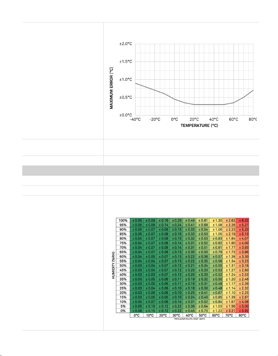
Accuracy Sensor measurement accuracy is variable across a range
of temperatures. Refer to the chart in Figure 4.
Figure 4 Temperature sensor accuracy
Equilibration Time
(t,63%)
<165 s (response time in 1 m/s air stream)
Long-Term Drift <0.03 °C/year, typical
Vapor Pressure
Range 0–47 kPa
Resolution 0.01 kPa
Accuracy Sensor measurement accuracy is variable across a range
of temperature and RH. Refer to the chart in Figure 5.
Figure 5 Vapor pressure sensor accuracy
7
AROYA

Barometric Pressure
Range 1–120 kPa
Resolution 0.01 kPa
Accuracy ±0.05 kPa at 25 °C
TEROS 12 Soil Moisture, Temperature,and Electrical Conductivity (EC) Sensor
Volumetric Water Content (VWC)
Range
Mineral soil calibration 0.00–0.70 m3/m3
Soilless media 0.0–1.0 m3/m3
Apparent dielectric
permittivity (ε𝛼)
1 (air) to 80 (water)
NOTE: The VWC range is dependent on the media the sensor is calibrated to. A custom calibration will
accommodate the necessary ranges for most substrates.
Resolution 0.001 m3/m3
Accuracy
Generic calibration ±0.03 m3/m3typical in mineral soils that thave solution EC
<8dS/m
Medium specific
calibration
±0.01–0.02 m3/m3in any porous medium
Apparent dielectric
permittivity (ε𝛼)
1–40 (soil range), ±1 ε𝛼(unitless)
40–80, 15% of measurement
Dielectric Measurement Frequency
70 MHz
TEROS12 Temperature
Range –40 to +60 °C
Resolution 0.1 °C
Accuracy ±0.5 °C from –40 to 0 °C
±0.3 °C from 0 to +60 °C
Bulk Electrical Conductivity (EC) TEROS 12 Only)
Range 0–20 dS/m (bulk)
Resolution 0.001 dS/m
Accuracy ±(5% + 0.01 dS/m) from 0–10 dS/m
±8% from 10–20 dS/m
8
SYSTEM

COMMUNICATION SPECIFICATIONS
Output
Gateway Ethernet (PoE)
Wireless communication Bluetooth mesh (Gateway, Repeaters, Sensors)
Sensor types SDI-12 based
Antenna
Make Raltron
Model number RST-W2-P-110-SMA-H
Gain 4.15 dBi
vertically polarized, dipole professionally installed
NOTE: This radio transmitter IC-5123A-MGM12P0 has been approved by Innovation, Science and Economic
Development Canada to operate with the antenna types listed below, with the maximum permissible gain
indicated.Antenna types not included in this list that have a gain greater than the maximum gain indicatedfor
any type listed are strictly prohibited for use with this device. Maximum Gain:4.15 dBi Vertically polarized, dipole.
PHYSICAL SPECIFICATIONS
Dimensions
Antenna 11.5 cm (4.53 in)
NOTE: Antenna is positioned straight out adding to the total length.
Gateway (H210)
Length 14.5 cm (5.71 in)
Width 10.5 cm (4.13 in)
Height 4.5 cm (1.78 in)
Repeater (H110)
Length 14.6 cm (5.75 in)
Width 10.2 cm (4.00 in)
Height 14.3 cm (5.63 in)
Climate Station (H111)
Length 15.5 cm (6.10 in)
Width 8.5 cm (3.35 in)
Height 3.7 cm (1.46 in)
9
AROYA

ATMOS 14 w/radiation shield
Diameter 10.0 cm (3.94 in)
Height 8.5 cm (3.35 in)
Sensor Station (H321)
Length 6.99 cm (2.75 in)
Width 18.00 cm (7.10 in)
Height 3.02 cm (1.19 in)
TEROS 12
Length 9.4 cm (3.70 in)
Width 2.4 cm (0.95 in)
Height 7.5 cm (2.95 in)
Needle length 5.5 cm (2.17 in)
Operating Temperature Range
Minimum –40 °C
Typical 50 °C
Maximum 80 °C
NOTE: Sensors may be used at higher temperatures under certain conditions;contact Customer Support
forassistance.
Cable
CAT 5E or better for all equipment
Connector Types
Gateway power RJ 45 PoE
Repeater power RJ 45 PoE
Climate Station power RJ 45 PoE
ATMOS 14 and TEROS12
sensor connection
M8 4-pin
(SensorStation, Repeater, Climate Station)
Communications port M8 4-pin
(SensorStation, Repeater, Climate Station)
10
SYSTEM

ELECTRICAL CHARACTERISTICS
Power
Lithium-ion (Li-on)
rechargeable battery
Battery cannot be replaced by the user.
NOTE: The Gateway device does NOT have a battery. It is powered over
Ethernet (PoE).
Power over Ethernet (PoE) 42.5–57.0 V, up to 25.5 W
CAUTION: If using a nonmanufacturer supplied PoE device to power this system,ensure that the voltage
rating does not exceed the recommended values stated above.The injector module used must comply with
IEEE 802.3af and must be able to supply at least 24 W for the Gateway to function as intended.
COMPLIANCE
Manufactured under ISO 9001:2015
3.2 COMPONENTS
This sections describes the components of the AROYA system.
3.2.1 GATEWAY H210
The Gateway provides sensor readings received from either a Repeater/Climate Station
(Section3.2.2) or Sensor Station (Section3.2.3) to the AROYA app for the customer to review.
The indicator light flashes orange when the device is powered from a PoE switch. Ensure the
device is powered by a device that supplies both Ethernet and power. The cable must be an
RJ 45 CAT 5E or better.
The Gateway operates using the following components:
• Power over Ethernet (PoE) module for continuous power
• 2.4-GHz Bluetooth low-energy chip antenna
11
AROYA

Antenna
LED indicates
active internet
connection
(flashing orange)
NOTE: If the internet
connection is slow,
the light may flash
green instead of orange.
This also indicates
active connection.
Front/top cover
(end cap)
Ethernet
POE port
(RJ 45)
Figure 6 AROYA Gateway—front, top view
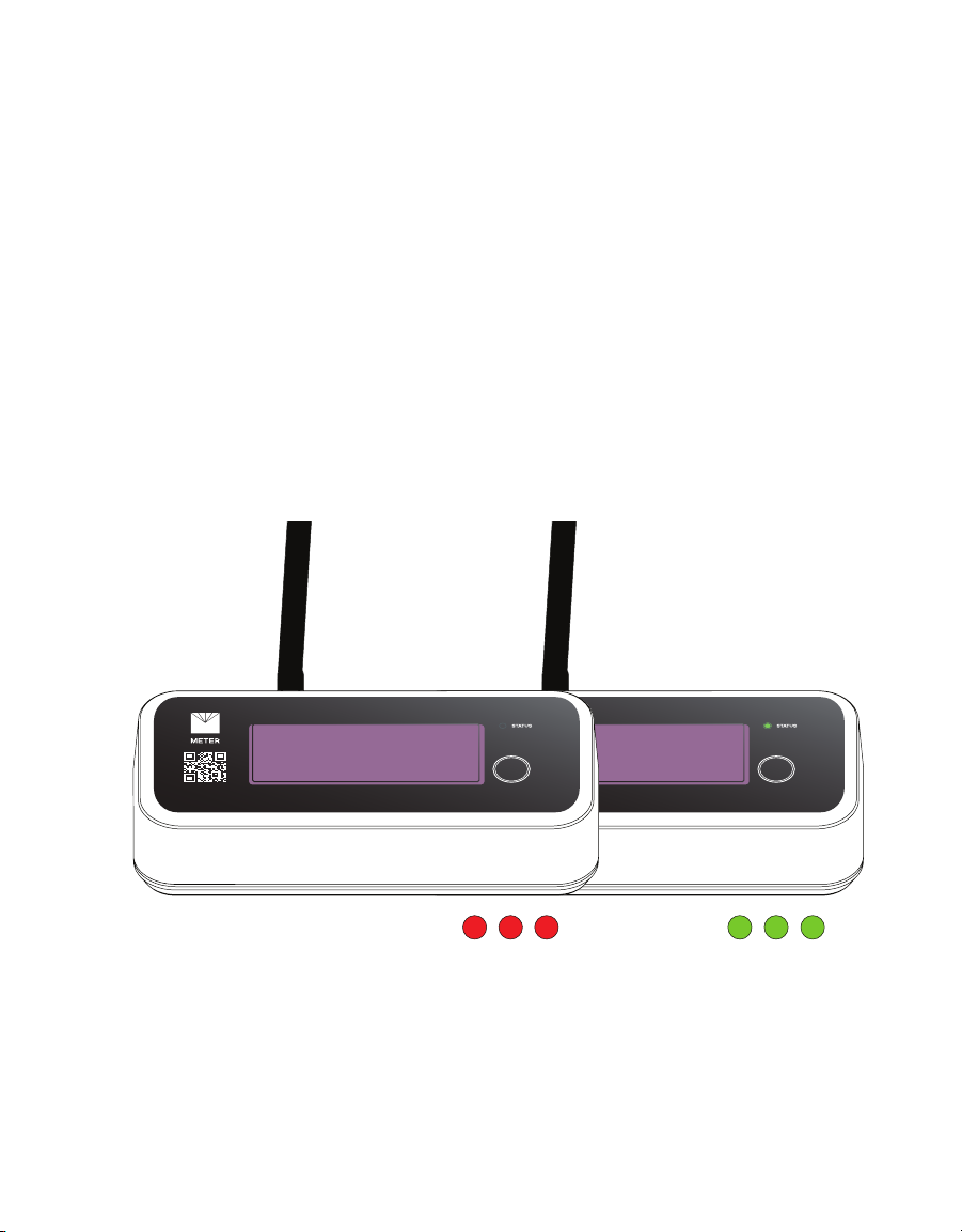
Antenna
Red LED
indicates
power status
Back/bottom
cover (end cap)
Figure 7 AROYA Gatewayback, bottom view
12
SYSTEM

3.2.2 REPEATER H110 AND CLIMATE STATION H111
The AROYA Repeater/Climate Station receives data from the Sensor Nose and transmits
data to the gateway wirelessly. The Repeater acts as a range extension for the network and
funnels the data to the Gateway device. The Repeater operates on a Bluetooth Mesh network
and relies on an active PoE connection to supply power to the device.
The Repeater and Climate Station both operate using the following components:
• PoE module for continuous power
• Rechargeable lithium-ion battery for back-up power
• 2.4-GHz two-way antenna for Bluetooth communication
• 38.4-MHz oscillator for high frequency, precise timing reference
• 32.768-kHz oscillator for low-frequency, low-energy timing reference
Blue LED
indicates
power ON
AntennaFront/top
cover (end cap)
M8 connectorsEthernet
POE port
(RJ 45)
Figure 8 AROYA Repeater—front, top view
The AROYA Climate Station receives data from the Sensor Nose and transmits data to the
Gateway wirelessly. The ATMOS 14, located in a radiation shield and attached to the Climate
Station, collects microclimate data that is also transmitted to the Gateway. The radiation
shield comprises a mounting bracket and seven discs. The shield prevents direct sunlight
from coming into contact with the sensor. This isolation from solar radiation prevents false
readings of elevated temperatures, allowing for accurate measurement of ambient air
temperature.
13
AROYA

Antenna
Ethernet cable
from Climate Station
Ethernet
cable to PoE
Repeater
ATMOS 14 in
radiation shield
Solar panel
PoE
gland
Climate
station
gland
Outer cover
Blue seal
grommet
Cap
Figure 9 AROYA Climate Station—front, top view
14
SYSTEM
3.2.3 SENSOR NOSE H321
Figure 10 and Figure 11 show the AROYA Sensor Nose. The Sensor Nose contain a
TEROS12 soil moisture sensor, location for plant, communication components, and antenna
to communicate data gathered by the TEROS 12 to the Repeater or directly to the gateway if
the base is close enough.
The Sensor Nose operates using the following components:
• Rechargeable lithium-ion battery
• Solar Panels for energy harvesting
• 2.4-GHz two-way antenna for Bluetooth communication
• 38.4-MHz oscillator for high frequency, precise timing reference
• 32.768-kHz oscillator for low-frequency, low-energy timing reference
The AROYA Senosr Nose is another version of the station with a different form factor allows
the TEROS 12 prongs to be inserted into the side of slabs. The Sensor Nose is powered with a
lithium-ion battery that is solar charged.
ON ON ONOFF OFF OFF
Figure 10 AROYA sensor nose—top view
15
AROYA
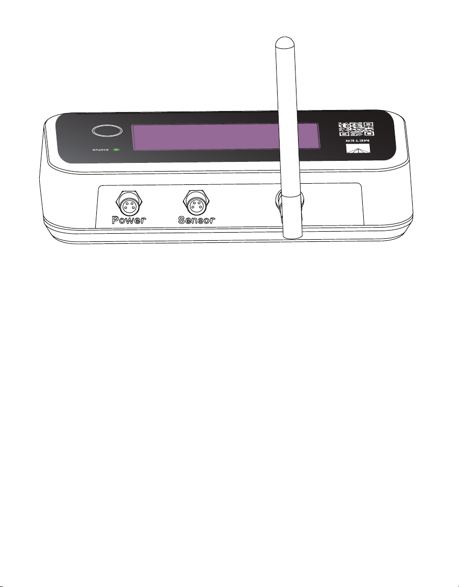
Figure 11 AROYA sensor nose—bottom view
16
SYSTEM

4. SERVICE
This section describes the calibration and maintenance of the AROYA. Troubleshooting
solutions and customer support information are also provided.
The AROYA Sensor Station, Sensor Nose, Repeater, and Climate Station, and Gateway should
be returned to METER in the event that it quits working for any reason or if the battery no
longer holds a charge. Please refer to Section4.2 for instructions for returning the product to
METER.
4.1 MAINTENANCE
AROYA hardward can be returned to METER in the need of maintenance. Refer to the RMA
section or contact Customer Support for more information.
NOTE: The user should not and cannot perform any maintenance. The battery is not accessible.
4.2 REPAIRS
METER repairs manufacturer defects and instruments within the 1-year warranty at no
charge. Repairs outside of the warranty window are charged based on cost of parts, labor,
and shipping. An extra fee may be charged for rush work. Contact Customer Support for an
estimated repair cost.
All AROYA units returning to METER for servicing must be accompanied with a Return
Merchandise Authorization (RMA) number. Prior to shipping the instrument, contact
Customer Support to obtain an RMA number.
1. Place the AROYA unit in a plastic bag to avoid disfiguring marks from the packaging.
2. Do not ship the power cord, serial cable, or any other accessories.
3. Ship the AROYA unit in its original box with suspension packaging.‘
4. If the original packaging is not available, use a box with at least 4 in of packing material
(e.g., StyrofoamTM peanuts or bubble wrap) between the instrument and each wall of the
box, ensuring the instrument is suspended in the packing material.
5. On the RMA form, please verify the ship to and bill to information, contact name, and
problem description. If anything is incorrect, please contact Customer Support.
6. Tape the box in both directions for added support.
7. Include the RMA number in the attention line on the shipping label.
17
AROYA
4.3 TROUBLESHOOTING
Table5 lists common problems and their solutions. If the problem is not listed or these
solutions do not solve the issue, contact Customer Support.
Table5 Troubleshooting
Problem Possible Solutions
Sensor is not reporting data
GATEWAY
Check that the device is powered on by observing the red light is on.
Confirm internet connectivity through the orange flashing light.
REPEATER and CLIMATE STATION
Check that the device is powered on (solid red light).
SENSOR NOSE
Make sure that the STATUS light flashes green upon pressing the
function button to indicate that the device is set on.
If the STATUS light flashes red upon pressing function button, then
the device is asleep. Press the function button until the light response
flashes green.
If problems with the device persist please reset the sensor hardware
by holding the press pad button for more than 5 s and wait to confirm
the light indicated reset for 5 s.
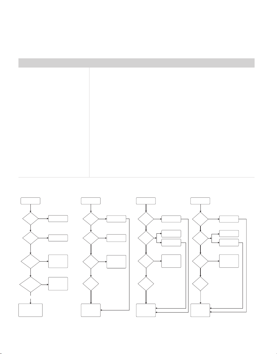
Existing Device/System Diagnostics
All devices offline
Gateway out of range
for closest repeater
Is gateway
reporting?
Red Light for
Power
Green-Yellow
flashing network
blink light ?
Connected to
modem _______ __
network switch ?
PoE needed to
power ON device
Verify upstream
devices are
connected to internal
and ports ____ and
8443 are not blocked
Modem/router or
settings may be
incompatible. Try an
unmanaged network
switch
Try connecting to other
network hardware or seek
IT assistance and
document network
equipment (brand/model)
Issue RMA and
replacement
Unknown
Device Family
Check repeater
radio power
Device per
Repeater limit
(12)
Device per
Repeater limit
(12)
Check battery
data
Check radio
power
Check radio
power
Weak Weak
Strong Strong
LowLow
Faulty Faulty
Single Substrate
offline
Power up repeater or
faulty repeater
Power up repeater or
faulty repeater
Ensure device is
plugged in and on
Replace and issue
RMA
Replace and issue
RMA
Spread repeaters to
balance load or
additional repeaters
needed
Spread repeaters to
balance load or
additional repeaters
needed
Verify sufficient light
levels j>15 ___2 for
12 hrs daily
Simple Repeater _14
offline
Issue RMA and
replacement
Issue RMA and
replacement
Unknown
Device Facility
Unknown
Device Facility
Check battery
data
Device per
Repeater limit
(12)
Adjust repeater
locations or additional
repeaters mended
Power up repeater or
faulty repeater
Spread repeaters to
balance load or
additional repeaters
needed
Verify all
repeators
are on
Modem
Good Good
Good
On
Poor
Off
Yes
Yes
YesYesYesYes
No No No No
No
No
Group/Floors of
devices offline
Network Switch
Figure 12 Existing Device/System Diagnostics
18
SERVICE
This manual suits for next models
3
Table of contents
Popular Switch manuals by other brands


Event Lighting
Event Lighting DIM4 user manual

Allied Telesis
Allied Telesis AT-8900 SERIES Troubleshooting

TerraTec
TerraTec MIDI HUBBLE manual

Zook
Zook Z-Alert installation instructions

Linksys
Linksys SGE2000 - Cisco - Gigabit Switch Administration guide

Siemens
Siemens SCALANCE XC-200 Configuration manual


