manuals.online logo
Brands
  1. Home
  2. •
  3. Brands
  4. •
  5. Festo
  6. •
  7. Switch
  8. •
  9. Festo SRBF-C series User manual

Festo SRBF-C series User manual

Limit switch attachment
SRBF−C...
Festo AG & Co. KG
Postfach
D−73726 Esslingen
++49/711/347−0
www.festo.com
(en) Operating instructions 749073
0911a
Original: de
1 Control sections and connections
1
2
3
4
5
6
7
8
9
aJ
aA
aB
3
1Housing cover
2Plastic hood with position
indicator (yellow/red)
3Mounting screws for housing cover
4Shaft
5Micro switches
6Cams (red, yellow)
7Mounting adapter  design
depends on the type èFig.2
8Back plate
9Earth terminal (PE)
aJ Cable connector
aA Terminal block (8−pin)
aB Spring
Fig.1: Design of control sections and connections of the limit switch attachment
2 Design
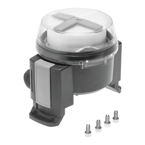
The SRBF−C limit switch attachment has a robust aluminium housing.
A transparent plastic hood in the cover allows a view of the three−dimensional
optical position indicator (èFig.1 2). Connected to the position indicator is a
shaft (èFig.1 4), which passes through the back plate to the outside.
The housing contains two micro switches (èFig.1 5), which are mechanically
actuated by cams (èFig.1 6) on the shaft. Through adjustment of the cams, the
desired switching points of the two micro switches can be set. Spring force presses
the cams onto toothed discs and in this way fixes the shaft in place (èFig.6).
To set the cams, they can be released from the toothed disc by pressing against
the spring force. The micro switches are designed as changeover switches
(èterminal diagram in Fig.5).
An 8−pin terminal block (èFig.1 aA ) inside the housing provides the electrical
connection. On the side, the limit switch attachment has a cable connector for the
wiring (èFig.1 aJ ).
On the opposite side, the housing is prepared for mounting an additional cable
connector for passing on the control signal for a solenoid valve (èterminal
diagram in Fig.5).
Four threaded holes in the back plate are used to fasten the mounting adapter.
This allows mounting of the semi−rotary drives with mechanical interface as per
VDI/VDE Directive 3845.
The SRBF−C limit switch attachment can be supplied with four different
premounted imounting adapters (hole pattern and shaft height èFig.2).
Characteristics Type code Description
Type SRBF Limit switch attachment
Design C Sensor box
Mechanical interface A3 Mounting adapter, hole pattern 30 x 80 mm,
for drives with shaft height 20 mm
A4 Mounting adapter, hole pattern 30 x 80 mm,
for drives with shaft height 30 mm
A5 Mounting adapter, hole pattern 30 x 130 mm,
for drives with shaft height 30 mm
A6 Mounting adapter, hole pattern 30 x 130 mm,
for drives with shaft height 50 mm
Type of indicator YR Position indicator yellow/red
Measuring range 90 0 ... 90°
Sensor principle MW Floating contact, changeover switch
Nominal operating voltage 22A 250 V AC 1)
Electrical connection C2 Screw terminal
Cable connector M20 M20x1,5, metal
1) For details ètechnical data in section 13
Fig.2: Type code of the SRBF−C limit switch attachment
3 Function
The rotary movement of the semi−rotary drive with process valve mounted below
the limit switch attachment is transmitted to the shaft (èFig.1 4) of the limit
switch attachment. The shaft transmits the rotary movement via cams
(èFig.1 6) onto the integrated micro switches (èFig.1 5) and the optical
position indicator (èFig.1 2). The optical position indicator shows whether the
process valve is open or closed. If the process valve is open, Open" is displayed
on a yellow background. Closed" on a red background shows that the process
valve is closed.
1Process valve
open:
Open" (yellow)
2Process valve
closed:
Closed" (red)
Fig.3: Position indicator (yellow/red)
12
Actuated micro switches switch (changeover switch, èterminal diagram in Fig.5).
The corresponding electrical signal is present at the electrical connection. This can
be passed on to higher−level systems for evaluation.
4 Application
The SRBF−C limit switch attachment is intended for recording, forwarding and
displaying of the end positions of semi−rotary drives in process automation
systems. And so the valve setting (open or closed) of the operated process valve is
recorded through the limit switch attachment.
Suitable for operation are semi−rotary drives for actuating butterfly valves and ball
valves in media−flow process valves (quarter−turn actuators) with slow movements
and few cycles.
Permissible are semi−rotary drives with mechanical interface as per
VDI/VDE Directive 3845, for which suitable mechanical adapter bridges are
available (èwww.festo.com/catalogue).
The maximum swivel angle of the limit switch attachment is 90°. The SRBF−C limit
switch attachment is suitable for use in the process industry and in an industrial
environment. The product is tailored to the requirements of the process industry
(è catalogue www.festo.com/catalogue).
5 Transport and storage
Ensure the following storage conditions are met:
 Short storage periods in cool, dry, shaded and corrosion−protected locations.
6 Requirements for product use
Installation and commissioning is to be carried out only by qualified personnel in
accordance with the operating instructions. When hazardous current and voltage
is involved, installation and commissioning must be performed by qualified
electricians.
Note
Improper handling can result in malfunctions.
· Make sure that all the instructions in this chapter are observed. The product
will then function correctly and reliably.
· Compare the limit values specified in these operating instructions with your
actual application (e.g. current, voltages, torques, temperatures). The product
can only be used in accordance with the relevant safety guidelines if the
maximum load limits are observed.
·Ifthe current is higher, the mechanical service life is reduced continuously.
Service life:
at24 V DC and ~200 mA: 1 000000 switching cycles
at24 V DC and ~1,5 A: 100000 switching cycles
at250 V AC and ~5 A: 6000 switching cycles
The product must be used in only one and the same circuit type throughout its
entire service life.
· Comply with all applicable national and international regulations.
· Remove the packaging. The packaging is intended for recycling
(except for: oiled paper = other waste).
· Take into consideration the ambient conditions at the location of use.
Corrosive environments reduce the service life of the product.
· Use the product only in the process industry and in an industrial environment, as
intended, in its original condition without any unauthorised modifications, in
perfect technical condition. Only the conversions and modifications described in
this documentation are permitted.
· The product is not a safety component and must only be used as designated.
·Ifadditional commercially−available valves are connected, the specified limits
for pressures, temperatures, electrical data, torques, etc. must be complied
with.
· Please select the appropriate accessories, such as mounting adapters,
couplings and electric cable, from our catalogue www.festo.com/catalogue.
7 Installation
Caution
Uncontrolled movements of the drive can cause damage when mounting.
· Before installing the limit switch attachment, make sure the compressed air
and power supply are switched off an the semi−rotary drive is not pressurised.
· Secure the system against being switched back on.
7.1 Mechanical installation
· Use a product variant with
an appropriate mounting
adapter for your drive
(mounting kits ècatalogue
www.festo.com/catalogue).
·Incombination with the DFPB,
use only a suitable mechanical
coupling 1.
· Mount the limit switch
attachment so that the required
working method is achieved.
1
For fastening to semi−rotary drives, the mounting adapters have a mounting hold
pattern in accordance with VDI/VDE Directive 3845
(ècatalogue www.festo.com/catalogue).
Before mounting
1. Bring process valve into the correct end position.
2. Ensure there is no voltage or pressure.
On mounting
The limit switch attachment is supplied with a mounted mounting attachment.
1. Align the shaft of the limit switch attachment so that it, the coupling, if
applicable, and the shaft of the semi−rotary drive engage each other in the
desired manner (example, see Fig.4).
1Semi−rotary
drive (here
DFPB)
2Coupling for
power
transmission
3Shaft of the
limit switch
attachment
Fig.4
1
2
3
2
2. Tighten the 4 fastening screws (Fig.1 8)  tightening torque max. 6 Nm ± 10 %.
7.2 Electrical installation
When hazardous current and voltage is involved:
Danger
Danger of death or serious bodily injury due to electric shock in case of exposed
electrical components!
· Switch off power before opening the device and when working on electrical
components.
· Connect the device to the power network in accordance with valid standards
and regulations so that it can be separated from the network with appropriate
switches (e.g. main switch).
· Connect the protective earth conductor (PE) correctly.
Warning
Installation errors can damage the electronics or cause malfunctions.
 Use an electrical connecting cable with a nominal outside diameter of
8 mm ... 13 mm
 Connect the earth terminal (èFig.1 9) with the earth potential with low
resistance (short cable with large cross−section)  tightening torque 1.3 Nm.
The electrical connection is established via an 8−pin terminal block (èFig.1 aA ).
To perform electrical installation, you have to open the device.
1. Switch off the power supply.
2. Loosen the 4 fastening screws (èFig.1 3) of the housing cover.
3. Route the electric cable through the cable connector.
4. Use the wire end sleeves suitable for the connection and wire the terminal block
according to the terminal diagram (èFig.5) 
cable cross section [mm³]: 0,5 ... 1.5; tightening torque 0.5 Nm.
Terminal diagram 1) Brief description
 Upper micro switch: changeover switch
(valve closed)
 Lower micro switch: changeover switch
(valve open)
MV= solenoid valve (optionally usable for
passing through the control signal for the
solenoid valve)
1) The terminal plan is attached to the inside of the housing cover.
Fig.5: SRBF−C terminal plan
5. Connect the earth terminal (PE èFig.1 9) with the earth potential with low
resistance (short cable with large cross−section)  tightening torque 1.3Nm.
6. Tighten the union nut of the cable connector  tightening torque 4 Nm. With this
you ensure pull resistance and IP protection.
8 Commissioning
During commissioning, the positions of the drive or process valve are determined,
in which the limit switch attachment is to deliver the desired signals (end
position1, end position 2). The rotatable cams (èFig.6 4,6 ) are hereby
released from the respective toothed disc by pressing or pulling against the spring
force and turned into the desired position. The closed position of the process valve
is switched through the upper red cam (èFig.6 6) and the open position
through the lower yellow cam (èFig.6 4) (èsection 8.1).
1Shaft
2Micro
switches (2)
3Toothed disc
4Cam (yellow)
5Spring
6Cam (red)
12
3
4
5
6
Fig.6
8.1 Setting switching points
Danger
High electrical voltage!
· Before working on the device, switch off all voltage (see section 7.2).
1. Close the process valve.
2. Switch off all power.
3. Loosen the red cam from the ring gear by carefully pressing the cam down.
4. Now set the switching point of the upper micro switch by turning the red cam
(acoustically or with a continuity tester).
5. After selecting the switching point, make sure that the red cam is pressed back
into the ring gear through spring force.
6. Open the process valve.
7. Now loosen the yellow cam from the ring gear by carefully lifting the yellow cam.
8. Set the switching point of the lower micro switch by turning the yellow cam
(acoustically or with a continuity tester).
9. Now check the signal behaviour of the limit switch attachment in a test run. To
correct switching points, repeat points 1. to 8.
To conclude commissioning
· Mount the cover of the limit switch attachment  tightening torque 2 Nm ± 10 %.
9 Operation
· Compare the maximum values specified in these operating instructions with
your actual application (e.g. pressures, forces, torques, masses, speeds,
temperatures). The product can only be used in accordance with the relevant
safety guidelines if the maximum load limits are observed.
10 Service and maintenance
If used as intended in the operating instructions, the device will be free of
maintenance.
11 Removal and repairs
Danger
· Before working on the electrical components, switch off all power
(see section 7.2).
Make sure that the following sources of energy are switched off:
 electrical power supply
 compressed air supply.
Information about spare parts and auxiliary means èwww.festo.com/spareparts.
12 Eliminating malfunctions
Malfunction Possible cause Remedy
Incorrect or unexpected signal Wire break Replace cable
pg
Position of the switching
points established incorrectly
Correct position of the
switching points
Micro switch defective Replace SRBF
Fig.7
13 Technical data
SRBF−C.. CA3−... CA4−... CA5−... CA6−...
Angle acquisition setting range [°] 0 ... 90
Based on standard ISO 5211, EN 60947−5−1
Type of fastening on flange as per ISO 5211 with accessories
Design square
Mounting position any
Mechanical interface see Fig.2
Measuring principle for proximity switches, mechanical/electrical
Switching element function changeover switch
Operating voltage range 1)
DCvoltage [V DC] 0 ... 24
 Alternating current AC [V AC] 0 ... 250
Max. switching capacity
DCvoltage [W] 36
 Alternating current AC [VA] 1770
Maximum allowed current dependent on ambient temperature 2)
 Ambient temperature 60 °C [A] 5
 Ambient temperature 70 °C [A] 4
 Ambient temperature 75 °C [A] 3
 Ambient temperature 80 °C [A] 1,5
Insulation voltage [V] 250
Surge voltage capacity [kV] 4
Connectable nominal conductor
cross section
[mm³] 0,5 ... 1,5
Protection class IP67
Ambient temperature [°C] −25 ... 80
Degree of contamination 3
Product weight [g] 655 680 710 725
Materials information
Housing die−cast aluminium, painted
Materials information for accompanying high−alloy stainless steel
pyg
accessories high−alloy steel
CE symbol (declaration of conformity) as per EC Low Voltage Directive
1) The product must be used in only one and the same circuit type throughout its entire service life.
2) If the current is higher, the mechanical service life is reduced continuously.
Fig.8

Other manuals for SRBF-C series

1

This manual suits for next models

4

Other Festo Switch manuals

Festo SME-1 Series User manual

Festo

Festo SME-1 Series User manual

Festo PE-PK Series User manual

Festo

Festo PE-PK Series User manual

Festo SOEL-RTH-Q20 User manual

Festo

Festo SOEL-RTH-Q20 User manual

Festo CAMC-G-S Series User manual

Festo

Festo CAMC-G-S Series User manual

Festo CRSMT-8 series User manual

Festo

Festo CRSMT-8 series User manual

Festo SME-8 Series User manual

Festo

Festo SME-8 Series User manual

Festo SMTO-1 C Series User manual

Festo

Festo SMTO-1 C Series User manual

Festo SME-8M-xxx-24V series User manual

Festo

Festo SME-8M-xxx-24V series User manual

Festo PE-PK Series User manual

Festo

Festo PE-PK Series User manual

Festo PEV-W-***-LED-G Series User manual

Festo

Festo PEV-W-***-LED-G Series User manual

Festo SRBE C1 Series User manual

Festo

Festo SRBE C1 Series User manual

Festo SME-CDC-DS-24V-SQM8 User manual

Festo

Festo SME-CDC-DS-24V-SQM8 User manual

Festo VPEV-1/8-M12 User manual

Festo

Festo VPEV-1/8-M12 User manual

Festo PEV-1/4-B-M12 User manual

Festo

Festo PEV-1/4-B-M12 User manual

Festo VPEV-W-***-LED-GH Series User manual

Festo

Festo VPEV-W-***-LED-GH Series User manual

Festo SME-8-K-LED-230 User manual

Festo

Festo SME-8-K-LED-230 User manual

Festo VPE-1/8 User manual

Festo

Festo VPE-1/8 User manual

Festo EduTrainer 576309 User manual

Festo

Festo EduTrainer 576309 User manual

Festo SMPO-1-H-B User manual

Festo

Festo SMPO-1-H-B User manual

Festo PEV-1/4A-SW27-B-OD User manual

Festo

Festo PEV-1/4A-SW27-B-OD User manual

Festo EAPM-L5-70-SLM User manual

Festo

Festo EAPM-L5-70-SLM User manual

Festo SMT-8M-***-24V Series User manual

Festo

Festo SMT-8M-***-24V Series User manual

Festo Compact Performance CP-FB6-E Quick guide

Festo

Festo Compact Performance CP-FB6-E Quick guide

Festo VABF-S4-A2G2 Series User manual

Festo

Festo VABF-S4-A2G2 Series User manual

Popular Switch manuals by other brands

Jung FAS180 Series operating instructions

Jung

Jung FAS180 Series operating instructions

hager HIM302 User instructions

hager

hager HIM302 User instructions

Edge-Core ES4005V installation guide

Edge-Core

Edge-Core ES4005V installation guide

Icy Box IB-HUB1701-U3 Quick installation guide

Icy Box

Icy Box IB-HUB1701-U3 Quick installation guide

H3C S3100V2-52TP Installation, quick start

H3C

H3C S3100V2-52TP Installation, quick start

UfiSpace S9180-32X Hardware installation guide

UfiSpace

UfiSpace S9180-32X Hardware installation guide

AMX RDM-2SWM Notice

AMX

AMX RDM-2SWM Notice

Maxxima MEW-S150DW Instruction guide

Maxxima

Maxxima MEW-S150DW Instruction guide

Fostex DS-8 Service manual

Fostex

Fostex DS-8 Service manual

Kramer VM-22H user manual

Kramer

Kramer VM-22H user manual

ATEN Altusen KM0032 user manual

ATEN

ATEN Altusen KM0032 user manual

Beijer Electronics Korenix JetNet 6728G Series Quick installation guide

Beijer Electronics

Beijer Electronics Korenix JetNet 6728G Series Quick installation guide

Airlink101 AKVM-2UDA Quick installation guide

Airlink101

Airlink101 AKVM-2UDA Quick installation guide

Monacor 25.5680 manual

Monacor

Monacor 25.5680 manual

ABB SACE Tmax XT manual

ABB

ABB SACE Tmax XT manual

HP 6125G Configuration guide

HP

HP 6125G Configuration guide

HP PROCURVE 2910AL Access security guide

HP

HP PROCURVE 2910AL Access security guide

Samsung SMART TV E-manual

Samsung

Samsung SMART TV E-manual

manuals.online logo
manuals.online logoBrands
  • About & Mission
  • Contact us
  • Privacy Policy
  • Terms and Conditions

Copyright 2025 Manuals.Online. All Rights Reserved.