Metkon ECOPRESS 52 Administrator Guide

1
metkon.com
OPERATION & INSTRUCTION MANUAL
AUTOMATIC MOUNTING PRESS

2
EC Declaration of Conformity
Manufacturer : Metkon Instruments Inc.
Address : Demirtas Dumlupinar Organize Sanayi Bolgesi
Ali Osman Sonmez Cd. No: 14 Bursa / TURKEY
Model No : ECOPRESS 52/102/202
Herewith declares that;
Hot Mounting Press,
is in conformity with the provisions of the Machinery Directive (directive 2006/42/EEC), as amended, and with national
implementing legislation;
is in conformity with the provisions of the Low Voltage Directive (directive 2014/35/EU), as amended, and with national
implementing legislation;
is in conformity with the provisions of the EMC Directive (directive 2014/30/EU), as amended, and with national
implementing legislation;
And furthermore declares that
the following (parts/clauses of) standards have been applied
EN ISO 12100:2010, TS EN 60204-1, TS EN IEC 61000-6-2, TS EN 61000-6-4
Authorized Person: ERCIN SENAY
Position: Manager of Research and Development Department
Year: 2019
Bursa / Turkey

3
Index
DESCRIPTION ............................................................................................................................ 4
Design .....................................................................................................................................................................................4
Technical Data ........................................................................................................................................................................5
Warranty .................................................................................................................................................................................6
Safety Precautions ..................................................................................................................................................................6
INSTALLATION & SET UP........................................................................................................... 7
Unpacking & Checking Contents of Package ...........................................................................................................................7
Step by Step Unpacking...........................................................................................................................................................7
Installation and Set-Up ...........................................................................................................................................................8
CONTROL PANEL (ECOPRESS 52).............................................................................................14
Control Button Functions ...................................................................................................................................................... 14
TOUCH SECREEN CONTROL PANEL (ECOPRESS 102/202).......................................................15
Control Button Functions ...................................................................................................................................................... 15
Password List........................................................................................................................................................................ 16
Operation Parameter Ranges ................................................................................................................................................ 16
Recommended Parameters ................................................................................................................................................... 16
OPERATION ..............................................................................................................................17
Making a Mould .......................................................................................................................17
Setting Parameters (for ECOPRESS 52) ...................................................................................18
Setting Parameters (for ECOPRESS 102/202)..........................................................................19
SERVICE AND MAINTENANCE ..................................................................................................21
Maintenance ......................................................................................................................................................................... 21
Troubleshooting....................................................................................................................................................................22
ACCESSORIES AND CONSUMABLES........................................................................................ 24
Mould Assemblies & Accessories ..........................................................................................................................................24
Consumables.........................................................................................................................................................................25
TECHNICAL DOCUMENTATION ............................................................................................... 26
Customer Service ..................................................................................................................................................................26
Hydraulic Wiring Diagrams....................................................................................................................................................26
4
DESCRIPTION
Design
All ECOPRESS models have electrohydraulic operation, which
do not require air. The sample is ejected fast and very
smoothly. All hydraulic components are housed in an ABS
cabinet, which is ergonomically designed.
ECOPRESS 52 is a cost effective automatic digital mounting
press with hydraulic pressure (requires no air). It is fully
automatic and suitable for all current hot mounting materials
used in materialography. User-friendly and modern-looking
control panel for mounting parameters provides high
productivity with last parameter settings being retained in the
memory. The control panel is specially designed to maximize
operator comfort and operation versatility. It is possible to set
mounting parameters in seconds.
ECOPRESS 52 is an easy to use mounting press. All button
controls, direct reading pressure gauge and valve are on the
front panel. Simply place the sample and the mounting media
in the cylinder and close the mold closure. Set the “Molding
Temperature”, “Heating Time”, “Cooling Time” and “Pressure”
then press the “Start” key. Pressure, heating and cooling are
automatically controlled and the total cycle time for a
complete cool mount takes 8 to 10 minutes. The actual
heating temperature and the heating time are digitally
displayed throughout the moulding cycle. The last parameter
settings are always retained in the memory. An audible signal
notifies the operator when the process is completed.
ECOPRESS 102/202 are high capacity, state of the art
automatic mounting presses having advanced software with
programmable colored HMI touch screen controls. Robust
bayonet closure allows for quick and safe operation. Wide
selection of mould assemblies from 25 to 50 mm in diameter
are available. Two mounts can be produced simultaneously
with the use of an intermediate ram. ECOPRESS 202, available
with dual cylinder can produce four mounts at a time offering
a perfect solution for labs with high specimen throughput.
ECOPRESS 102/202 have preprogrammed moulding
sequences built-in (factory set) from which you can choose
according to your own applications. You only need to place
the sample in the mould, select the program number for your
specific application and depress the “Start” button. That is it!
ECOPRESS does the rest for you! After pressing the start key,
the fully automatic program sequence is executed with the
preselected parameters. The pressure, heating and cooling
are automatically controlled and the total cycle time of a
complete cool mount takes 8 to 10 minutes. The parameters
can be changed and adjusted during the mounting process.
ECOPRESS 102/202 has additional capacity to store up to 99
operator-created programs. User-friendly program data and
instructions are displayed on a large touch screen LCD.
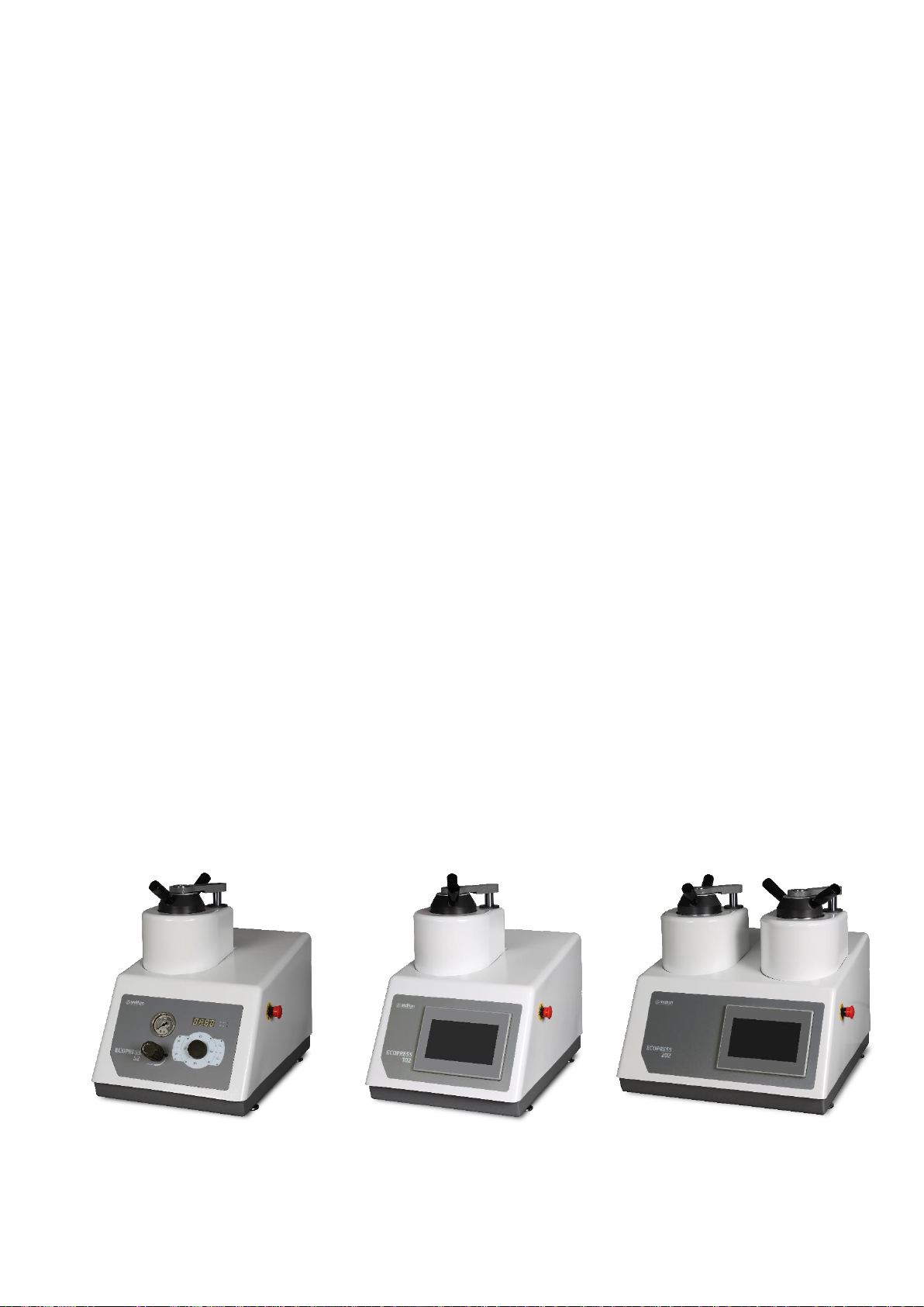
ECOPRESS 52
ECOPRESS 102
ECOPRESS 202

5
Technical Data
Model
Order No
ECOPRESS 52
25 10
ECOPRESS 102
25 11
ECOPRESS 202
25 12
Number of Moulds
1
1
2
Maximum Pressure, bar
300 bars
300 bars
300 bars
Maximum Temperature, °C
200 °C
200 °C
200 °C
Heating Power, Watt
1650 W
1650 W
2 x 1650 W
Fast Cooling
Yes
Yes
Yes
Slow Cooling
Yes
Yes
Yes
Operation
Automatic
Programmable
Automatic
Programmable
Automatic
Display
Digital Display
7” Colored
Touch Screen LCD
7” Colored
Touch Screen LCD
Mould Assembly, mm
25-50 mm
25-50 mm
25-50 mm
Dimensions, mm, WxDxH
360 x 560 x 470
360 x 560 x 470
470 x 560 x 470
Weight, kgs
37 kgs
38 kgs
54 kgs

6
Warranty
The ECOPRESS is guaranteed against defective material or
workmanship defects for a period of 12 months from the date
of receipt by the customer or latest 18 months after the
shipping date. The warranty is not valid if inspection shows
evidence of misuse or unauthorized repair. Warranty covers
only replacement of defective materials. If this unit need to be
returned to our factory for service, please contact your
distributor for authorization and include the following details:
Serial Number of the unit, Invoice number and date. Transport
costs belong to the customer.
NOTE
The equipment is designed to be used with
METKON accessories and consumables. In case of
misuse of equipment, improper installation,
alteration, use of different source parts, improper
repair, METKON will accept NO responsibility for any
damages to the operator or the equipment. Disassembling of
any part should always be performed by a qualified
technician
Safety Precautions
Read the below instructions carefully before use.
Place the machine on a sturdy and safe platform.
The equipment must be installed in compliance with
local safety regulations.
Only use approved METKON accessories and
consumables to achieve maximum safety and lifetime.
Follow the instructions and safety regulations when
lifting and carrying the equipment.
Be sure that the water connections are assembled
properly without any water leakage.
Be sure that the water outlet hose is safely assembled to
the outlet connection.
Be sure that the mould assembly is properly installed on
the mounting press before starting the process.
Be sure that the top closure and the upper ram is
correctly mounted before starting the process.
Do not operate the mounting press with a higher
force/pressure than the parameters recommended for
the actual cylinder diameter.
In case of mounting powder swallow, please contact to
your doctor.
Do not operate the unit without installing the mould
assembly.
Do not operate the unit without mounting powder.
Disconnect the electrical connection before servicing the
equipment.
Follow the periodically maintenance.
NOTE
METKON Instruments Inc. can make any changes
without notice on the equipment, accessories,
consumables and miscellaneous products.
Consequently; visual or written information on
the instruction manuals, technical materials, catalogues,
website, product videos and other marketing materials may
show inconsistencies and may be different from the product.
7
INSTALLATION & SET UP
Unpacking & Checking Contents of Package
Carefully unpack and check contents of the package. If any
components are missing or damaged, save the packing list
and materials and advise your distributor and the carrier of
the discrepancy.
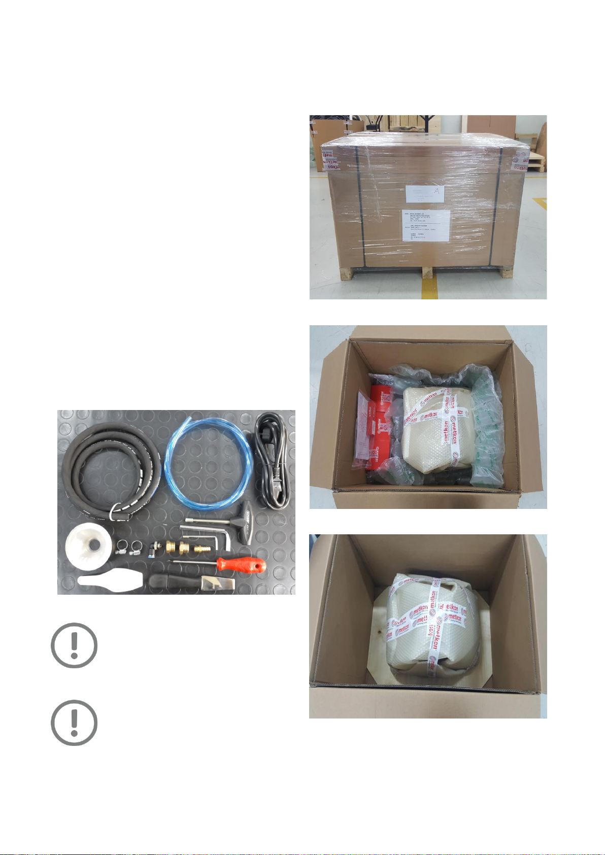
Carefully unpack and check that the following items have
been received:
Drain Hose for Hot Water, 1.5 m, 1 piece
Water Inlet Hose, 1.5 m, 1 piece
Power Cable, 1.8 m, 1 piece
Aluminium Funnel, 2 pieces
Hose Clamp, Ø10 –Ø16 mm, 2 pieces
Pneumatic Fitting, 8 mm to ¼”, 1 piece
Brass adapter, ¼”to ½”, 2 pieces
Nozzle, ¼”to 10 mm, 1 piece
Magnetic Bits Holder, T-type, 6.3 x 100 mm, 1 piece
Screwdriver, 6 x 100 mm, 1 piece
Hex Key, 8 mm, 1 piece
Hex Key, 4 mm, 1 piece
Scale, 1 piece
Spatula, 1 piece
WARNING
Please consider the weight of equipment and
be sure that there are enough people (at least
2) or lifting equipment to lift safely for
transportation. It is recommended to wear
safety shoes during transportation.
ATTENTION
ECOPRESS is bolted to a wood base for
protection during shipping. Remove the bolt
securing the unit to the wood base.
Step by Step Unpacking
Carefully remove the outer stretch wrap, cut the strips
and remove the cover.
Open the box and remove filling materials inside the box.
Remove the consumables first.

8
Remove the equipment from the box by holding the
bottom. Be careful not to damage ABS cover when lifting.
Please consider weight of equipment when lifting it. Lift
the equipment by considering the center of gravity.
Carefully remove the protective bubble wrap. Be carefull
not to damage equipment while using a knife.
Remove the protective foam on the touch screen
(ECOPRESS 102/202).
Installation and Set-Up
CAUTION
Follow approved procedures and take all
necessary preventive safety measures when
lifting and installing this equipment. Improper
lifting can result equipment damage.
ECOPRESS is available either as bench top or with
cabinet.
ECOPRESS should be placed on a sturdy and safe
platform. Please be sure that the platform is large enough
and can stand its weight.
In order to work with equipment comfortably, it is
recommended to leave at least 30 cm space from all side
of the equipment.
You can see the dimensions and weights of ECOPRESS
series:
ECOPRESS 52
Dimensions
W
D
H
36 cm
56 cm
47 cm
Weight
Approx. 37 kgs
ECOPRESS 102
Dimensions
W
D
H
36 cm
56 cm
47 cm
Weight
Approx. 38 kgs
ECOPRESS 202
Dimensions
W
D
H
47 cm
56 cm
47 cm
Weight
Approx. 54 kgs
ATTENTION
IN ORDER TO PREVENT OIL LEAKAGE FROM
THE RESERVOIR, DO NOT TILT THE
EQUIPMENT.
9
Electrical Installation
Before making electrical connections, check that the voltage
and frequency stated on the specification plate correspond to
the local voltage and frequency. Check that the values for
mono-phase voltage if it is compatible with the intended
electrical supply before installation.
ATTENTION
Connect the unit to the grounded mains
voltage.
WARNING
Electrical Shock Hazard. A qualified electrical
technician should perform all hard wiring and
electrical maintenance.
Disconnect the power supply before making any
electrical adjustments.
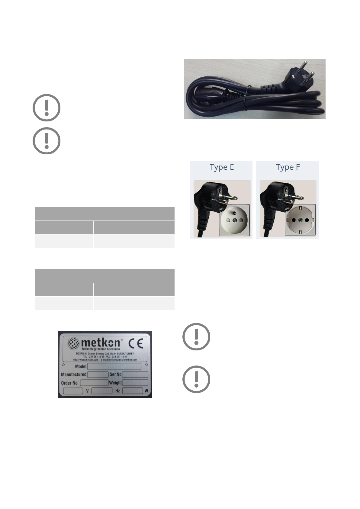
Make sure that the supply voltage and frequency is
correct. Check the values from the machine identification
plate located at the rear of the machine:
ECOPRESS 52/102
Voltage / Frequency
Operational
Power Range
Fuse Rating
230 V, 50/60 Hz. 1 ph.
200 - 250 V
10A (C Type)
115 V, 50/60 Hz. 1 ph.
100 - 125 V
20A (C Type)
ECOPRESS 202
Voltage / Frequency
Operational
Power Range
Fuse Rating
230 V, 50/60 Hz. 1 ph.
200 - 250 V
20A (C Type)
115 V, 50/60 Hz. 1 ph.
100 - 125 V
32A (C Type)
Identification Plate
Connect the equipment to the grounded mains voltage.
Power cord will be supplied with the equipment.
Length of power cable is 1.8 meters.
Power Cable
You can see suitable power sockets as below. If you have
not suitable power socket, in this case you should supply
a suitable power cord.
Water & Cable Connections
ECOPRESS requires water supply with a minimum of 2
liters/min flow rate.
Maximum water pressure must not exceed 3 bars. Well
water or hard water must not be used.
Lower water flow rate and pressure will not affect the
operation of the ECOPRESS but longer cooling times may
be needed.
ATTENTION
A Hydrophore generates much higher water
pressure than city water. This causes input
hose to blow out and solenoid valve to be
damaged. Maximum water pressure must not exceed 3 bars.
ATTENTION
Well water or hard water causes solenoid valve
to be clogged up and broke down due to dirt
and lime.

10
If the equipment used with well water, hydrophore or
very hard water; a water filtering and pressure regulator
system must be used. Please contact Metkon Service
representative if you need water filtering and pressure
regulator system.
Water Filtering and Pressure Regulator System
Water inlet and drain hoses will be sent together with the
equipment. (See: Installation Kit)
See diameters of hoses as below:
Drain Hose:
Interior diameter: 5/16”
Outer diameter: 14 mm
Water Hose:
Interior diameter: 5 mm
Outer diameter: 8 mm (5/16”)
Please be sure that there are enough space or holes for
hoses at the backside of the equipment.
Below fittings will be sent for water hose connection
together with the equipment :
Connect the line water to the unit with the plastic tube
supplied.
Fix the copper tube to the water outlet of the unit to the
drain.
Connections
CAUTION
After making the connection of line water and
drains please check if any leaks are occurred or
not, before any electrical connection.
ATTENTION
There is a small blue plug at the backside of the
equipment, which is used for transport. This
plug is used to prevent oil leakages during the
transport. Please take the plug out before using the
equipment and do not use it anymore unless you will
transport it somewhere.
NOTE: If for any reason the ECOPRESS has to be moved, close
the small blue plug before moving and open before
operating.
Optional Recirculating Cooling System
The GR 1363 Recirculating Cooling System is composed of 40
liters stainless steel cooling tank, 24V recirculating pump and
connection hoses, etc.
Recirculating Cooling System
Follow below steps to make recirculating cooling system
ready for operation:
Position the recirculating cooling tank below level of
ECOPRESS.
Fit the blue inlet pipe to the ECOPRESS
Fit the black hose to the drain outlet on the ECOPRESS.
Fill the tank with fresh water.
Mains Cable
Connection
Drain Water
Outlet
Water Inlet
Transport
Plug

11
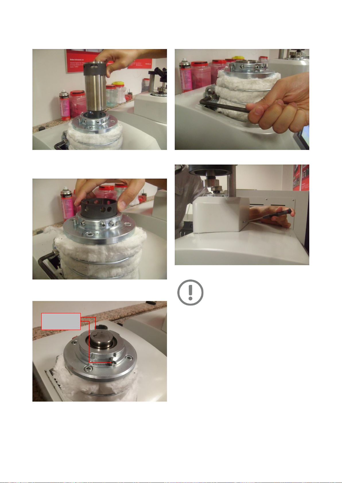
Mounting Mould Assembly
ECOPRESS is shipped as completely assembled. However if
you need to change the mould or assemble it later for any
reason, follow the below steps to assemble the mould:
Take out the mould closure completely.
Remove the two fixing screws from back of the ABS
cover of the mould chamber then, remove the upper ABS
cover.
Take out the bottom ram then, lower the ramrod to the
bottom.
Disassemble the screws and take out the upper part
metal thread of the mould.
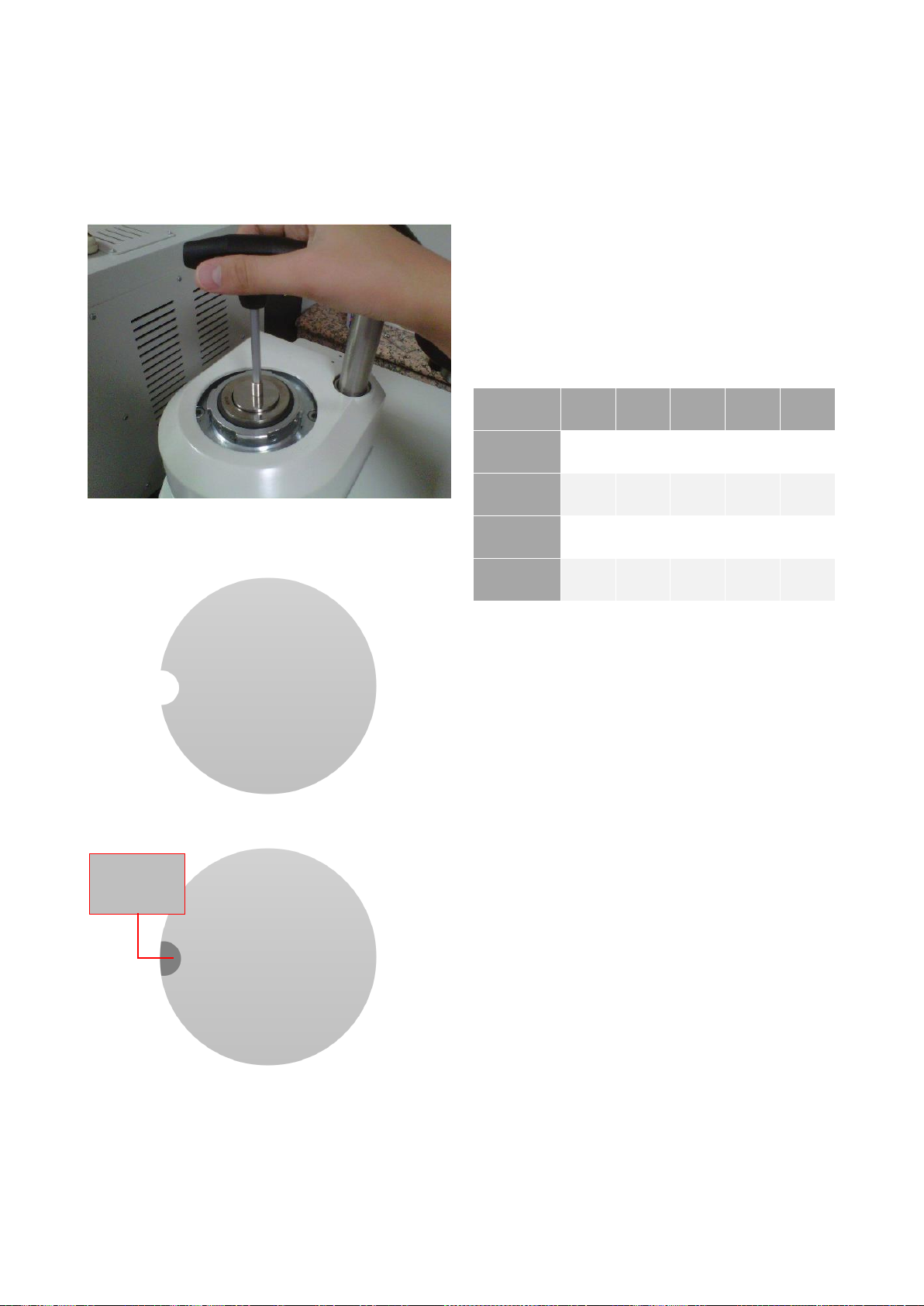
Tighten (clockwise) the Cylinder Lock screw.
Take out the mould assembly as shown in below photo:
Remove
these screws
12
Replace your mould assembly. Insert the mould assembly
until it sits level with the mould closure.
Insert the Mould Cylinder Insulator Ring into the Mould
Closure. Align the holes of the Insulator Ring with the
screws.
Assemble the upper part metal thread of the mould cover
and tighten the screws.
Loosen (counterclockwise) the Cylinder Lock screw
shown on below photo:
Close the upper cover and assemble the screws.
IMPORTANT!
You should order the mould assembly
according to dimensions and shape of your
sample. Big samples, which touch the inner
wall of moulds, can scratch the mould assembly. In addition,
using less hot mounting powders than the required can
scratch the mould assembly. Please keep in mind that this
kind of damages due to operator fault are not covered by
warranty.
Tighten these
screws
13
Using Intermediate Ram
You can get double mounts in one cycle by using
intermediate ram. After placing your first sample and
mounting compound, insert the intermediate ram with the
help of the magnetic ram holder. Then put your second
sample and mounting compound.
Please clean the material accumulated at the groove of the
intermediate ram as shown below before each operation for
safety.
Intermediate Ram before Operation
Intermediate Ram after Operation
Be sure that the resin that you put on the sample exceeds
the sample height enough.
Maximum height of the samples should be 10 mm.
If the put resin is not enough, the sample may touch to
the upper ram or to the intermediate ram. This will distort
the intermediate ram and the inner surface of the mold
assembly.
Do not put your specimen close the edge of mould.
Otherwise, the sample may scratch the mould.
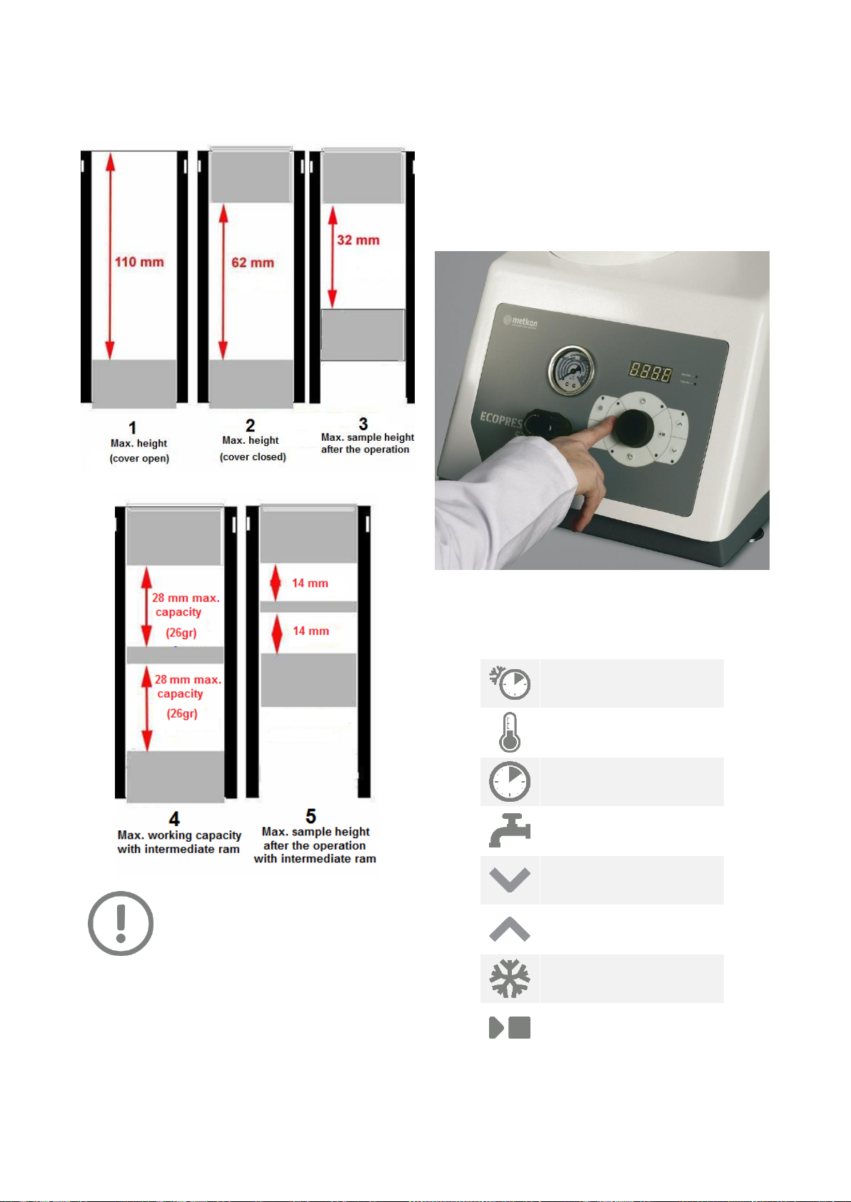
Each mounting compound has different melting and cooling
properties. Therefore, the working capacity and amount of
powder would be change for each powder. Below table
shows general dimensions according to different compounds
in Ø40 mm mould assembly.
No
1
2
3
4
5
Phenolic
110 mm
62 mm
32 mm
28 mm
(26 gr)
14 mm
Epoxy
110 mm
62 mm
33 mm
28 mm
(38 gr)
15 mm
Acrylic
110 mm
62 mm
40 mm
28 mm
(25 gr)
17 mm
Diallyphtalat
110 mm
62 mm
27 mm
28 mm
(28 gr)
12 mm
Above-mentioned information has been given as a reference
for Ø 40 mm to give an idea about the mounting compound
transformation.
Accumulated
Material Must
be Cleaned
14
Below table shows capacity of the moulds in different stages
while using phenolic mounting powder in Ø40 mm mould
assembly.
ATTENTION
All mould jamming and scratching problems
caused by operator fault are out of warranty!
Noise Level
Approx. 60 dB is measured at idle running at a distance of 1 m
from the machine.
CONTROL PANEL (ECOPRESS 52)
ECOPRESS 52 has a modern looking and easy to use operator
panel with buttons and knob. It has specially designed to
increase operator comfort and maximize productivity. All
mounting parameters can be set easily and quickly. A
multipurpose digital display allows you to observe all
parameters.
ECOPRESS 52 Control Panel
Control Button Functions
Cooling Time
Heating Temperature
Heating Time
Manual Cooling
Ram Down
Ram Up
Slow Cooling
Start/Stop

15
TOUCH SCREEN CONTROL PANEL
(ECOPRESS 102/202)
The operation panel is a 7’’ touch screen LCD. HMI touch
screen controls increasing the productivity, sample
consistency and operator comfort.
ECOPRESS 102/202 HMI Touch Screen
Control Button Functions
Main menu
Metkon contact info
Service and maintenance menu
Information
Language Selection
Bar/PSI Selection
°C/°F Selection
Consumable List
Application Areas
Automatic Mounting Menu
Temperature Parameters
Pressure Parameters
Heating Time Setting
Mould Dimension Selection
Cooling Parameters
Switch to Left Mould
Switch to Right Mould
Ram Up
Ram Down
Manual Cooling
Load Existing Program
Save Parameters

16
Password List
Below are passwords, which are required for operating and
programming the machine. You can use any of them.
Username
Password
Start-up Password
1840
USER1
1234
USER2
123456
USER3
1000
Operation Parameter Ranges
Heating Temperature : 0 –200 °C
Preheating Temperature : 0 –199 °C
Pressure for Ø25-30-40 : 0 –300 Bar
Pressure for Ø50 : 0 –220 Bar
Preload Pressure for Ø25-30-40 : 20 –299 Bar
Preload Pressure for Ø50 : 20 –219 Bar
Heating Time : 0 –35 Mins
Mould Size, mm : Ø25-30-40-50 mm
Mould Size, inch : Ø1”-1 ¼”-1 ½”-2”
Stand-by Temperature : 0 –60 °C
Recommended Parameters
For Ø25 and Ø30 mm Mould Assemblies
Moulding
Resin
BAK/CON
DAP
EPO
NET
Heating
Temperature
170 °C
180 °C
180 °C
150 °C
Pressure
250 bar
210 bar
210 bar
230 bar
Curing Time
3-4 mins
4-5 mins
4-6 mins
3-4 mins
Cooling
Method
Cooling
Based on
Time
Cooling
Based on
Time
Cooling
Based on
Time
Slow
Cooling
Cooling Time
3-4 mins
3-4 mins
3-4 mins
5 sec ON
30 sec OFF
For Ø40 mm Mould Assemblies
Moulding
Resin
BAK/CON
DAP
EPO
NET
Heating
Temperature
170 °C
180 °C
180 °C
150 °C
Pressure
250 bar
210 bar
210 bar
230 bar
Curing Time
2-3 mins
3-4 mins
4-5 mins
3-4 mins
Cooling
Method
Cooling
Based on
Time
Cooling
Based on
Time
Cooling
Based on
Time
Slow
Cooling
Cooling Time
3-4 mins
3-4 mins
3-4 mins
5 sec ON
30 sec OFF
For Ø50 mm Mould Assemblies
Moulding
Resin
BAK/CON
DAP
EPO
NET
Heating
Temperature
170 °C
180 °C
180 °C
150 °C
Pressure for
Ø50 Mould
210 bar
210 bar
210 bar
210 bar
Curing Time
2-3 mins
3-4 mins
4-5 mins
3-4 mins
Cooling
Method
Cooling
Based on
Time
Cooling
Based on
Time
Cooling
Based on
Time
Slow
Cooling
Cooling Time
3-4 mins
3-4 mins
3-4 mins
5 sec ON
30 sec OFF
NOTE
These are the minimum parameters to obtain a
good mount in the shortest time. Higher values
do not cause negative effect on the mount
quality but total cycle time may be increased. Sample shape,
powder amount and temperature of city water may effect
the mount quality. If you cannot obtain good sample with
these parameters, please try different parameters by
following recommendations on the troubleshooting section.
17
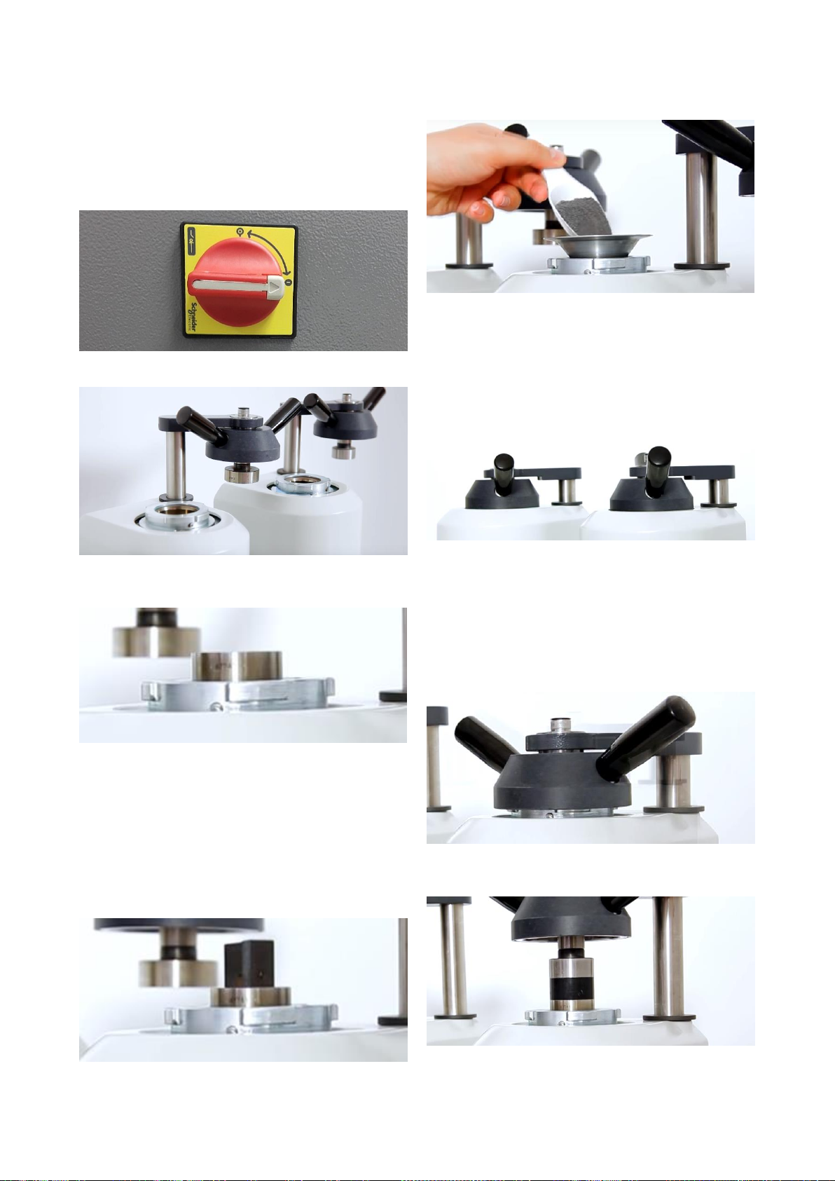
OPERATION
Making a Mould
Turn on the equipment from the main switch at the rear
side.
Open the bayonet closure.
Move the ram upmost position by pressing “Ram Up”
button.
Clean the powder residue from the upper and bottom
rams. Brush away any loose mounting material or other
deposits from around the mold area before making a
mold.
Apply Mould Release Spray after every fifth or sixth mold
to prevent buildup of molding powder on the inside of
the mold cylinder and the outside faces of the upper and
lower rams.
Put a specimen on the ram as below.
Move the ram to the bottom position by pressing “Ram
Down” button.
Put enough amount of mounting powder inside the
mould.
Clean the sidewalls of the mould and upper ram.
Otherwise, upper ram cannot go inside the mould and
bayonet closure cannot be closed. Because there is very
small tolerance between the rams and mould.
After cleaning, close the bayonet closure. Be sure that
the closure is closed properly. Hear the click noise to be
sure that it is closed properly. Otherwise, the thread of
the closure may break under pressure.
Set parameters or select a specific program and press
“START” button. The mounting cycle will be completed
automatically. An audio signal will notify the operator
when mounting operation is completed.
After mounting operation is completed, turn the bayonet
closure to unlock it. Do not try to pull it up. Because, the
upper ram is expanded due to temperature and cannot
be moved up easily.
Press “Ram Up” button to move ram up. You can take
your specimen.

18
Setting Parameters (for ECOPRESS 52)
Adjusting Pressure
Follow below steps to adjust pressure:
Put some mounting powder inside the mould and close
the bayonet closure.
Press “START” button.
Wait until bottom ram goes up and apply pressure.
Pull up the pressure regulator to unlock it.
Set the pressure by turning pressure regulator. Observe
the pressure from the gauge.
After desired pressure value is set, push the pressure
regulator to lock it.
Press “STOP” button.
The pressure is set!
Gauge
ATTENTION
The maximum allowable pressure for different
types of moulds are marked on the gauge.
Never increase the pressure into the “DANGER”
zone. This may damage the hydraulic system.
Warranty will not cover the damages due to operator fault.
NOTE
The pressure is already set in the METKON
Factory according to purchased mould
diameter and Bakelite mounting powder (BAK).
However, if you change the mold later with
different diameter, it is required to adjust the pressure. If you
are using different type of mounting powders, you do not
have to change pressure parameter every time. You can use
same pressure parameter for each mounting powders. Just
adjust the pressure parameter for the mounting powder,
which require the highest pressure.
ECOPRESS 52 Control Panel
Moving the Bottom Ram
Press “Ram Down” button to move the ram downwards.
Press the same button again to stop the ram.
Press “Ram Up” button to move the ram upwards. Press
the same button again to stop the ram.
Setting Heating Temperature
Press the “Heating Temperature” button. The LED of this
button will blink and the last parameter will be seen on
the display.
Set heating temperature by turning knob.
Push the knob to save heating temperature.
Heating temperature is set.
Setting Heating Time
Press the “Heating Time” button. The LED of this button
will blink and the last parameter will be seen on the
display.
Set heating time by turning knob.
Push the knob to save heating time.
Heating time is set.
Setting Cooling Time
Press the “Cooling Time” button. The LED of this button
will blink and the last parameter will be seen on the
display.
Set cooling time by turning knob.
Push the knob to save cooling time.
Cooling time is set.
19
Slow Cooling
Slow cooling feature is used while moulding with
Transparent Acrylic Powder (NET). This mounting powder
will be clear only with the slow cooling.
When you press “Slow Cooling” button, the LED of this
button will be on and slow cooling mode will be
activated. In slow cooling, the cooling water will be on
for 5 second, will be off for 30 seconds. This cycle will
continue until mould temperature reaches to 35 °C.
When slow cooling mode is active, the cooling time
parameter will be deactive.
Press same button again if you want to deactive the slow
cooling mode. The LED of this button will be off and slow
cooling mode will be deactivated.
Changing the Slow Cooling Parameters
Keep pressing the “Slow Cooling” button for 5 seconds.
The final temperature will be seen on the display. Set the
final temperature by turning knob and press on the knob
to save the parameter.
After that, press “Slow Cooling” button. Now, the “water
on time” will be seen on the display and the LED of this
button will blink. Set and save the “water on time” by
knob in same way.
Finally, press again “Slow Cooling” button. Now, the
“water off time” will be seen on the display and the LED
of this button will blink. Set and save the “water off time”
by knob in same way.
Manuel Soğutma
When you press “Manual Cooling” button, the LED of this
button will be on and cooling water will be active. The
water circulation will continue as long as manual cooling
mode is active.
Press the same button again to turn off the cooling water.
Start and Stop
Press the “Start/Stop” button to run or stop the
equipment. The LED of this button will be on when
equipment is running.
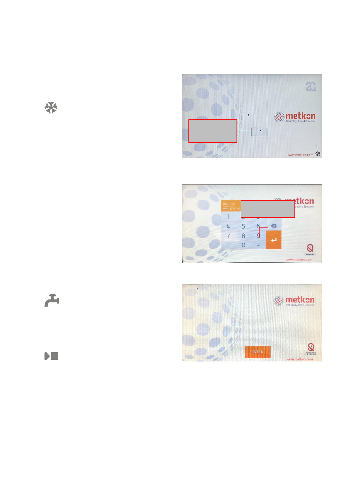
Setting Parameters (for ECOPRESS 102/202)
Turn on the equipment from the main switch at the rear
side. The screen will become light up as below.
Starting Screen
Enter the starting password: 1840
Entering the Starting Password
Press ENTER button to continue.
Starting Screen
Press here to
enter the starting
password.
ENTER the starting
password: 1840
20
The menu will appear as below. Press MAIN MENU
button to continue.
Starting Menu
The MAIN MENU will appear as below:
Main Menu
Service and Maintenance Menu - From this menu, you
can see the lists of possible faults, for periodic
maintenance, and the factory settings.
Service and Maintenance Menu
In order to have Access to the “maintenance” division, you
need to login. The user name is “USER 1” and the password is
“1234”.
You can follow the instructions listed in this menu for
maintenance and monitoring of your equipment. The date and
the time is also set in this menu.
ATTENTION
Every week, month & year you will be advised
of required maintenance procedures via the
machines software. The functions will not
work unless you adhere to the maintenance
menu.
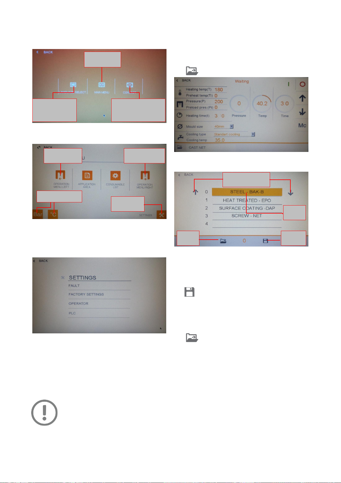
Creating and Saving Mounting Parameters
Set all the parameters from the touch screen and depress
“Load” button.
Operation Menu
Program Save/Load menu will appear as below:
Save Program
Select an empty area by the help of up/down arrows.
Touch the naming area.
Type a specific program name.
Press save button.
NOTE: The parameters can be changed and adjusted
during the mounting process.
To load an existing program, select an existing program
by the help of up/down arrows and then press the “Load”
icon.
You can change
the language
from this menu
Enters the
MAIN MENU
You can see the
contact information
of METKON.
Mould Selection
(Left)
Mould Selection
(Right)
Metric / Imperial
Service &
Maintenance
Move up & down for
program numbers
Program
Save
Program
Load
Naming
Area
This manual suits for next models
5
Table of contents
Popular Power Tools manuals by other brands

Würth
Würth 1952 004 530 Translation of the original operating instructions

Makita
Makita HM1810 instruction manual

Powerfix Profi
Powerfix Profi PKRS 1.5 A1 operating instructions

Chicago Electric
Chicago Electric 66001 Set up and operating instructions

Berner
Berner BACHG Original instructions

Grizzly
Grizzly G9859 instruction manual


