WHAT'S
IN
THE
BOX
Harley-Davidson
Street
Glide
and
Road
Glide
2014-2022
Infinity
and
Saddle
Tramp
two
speaker
kit
Visit
metraonllne.
c
om
to
view
the
available
installation
parts
and
Motorcycle
accessories.
Not
compatible
with
the
Rockford
Fosgate
OE
system
.
KIT
FEATURES
•
Kappa
Perfect
6.5"
speakers
•
All
installation
equipment
provided
•
For
2014
-
2022
Harley
Davidson
Street
and
Road
Glide
motorcycle
fairings
•
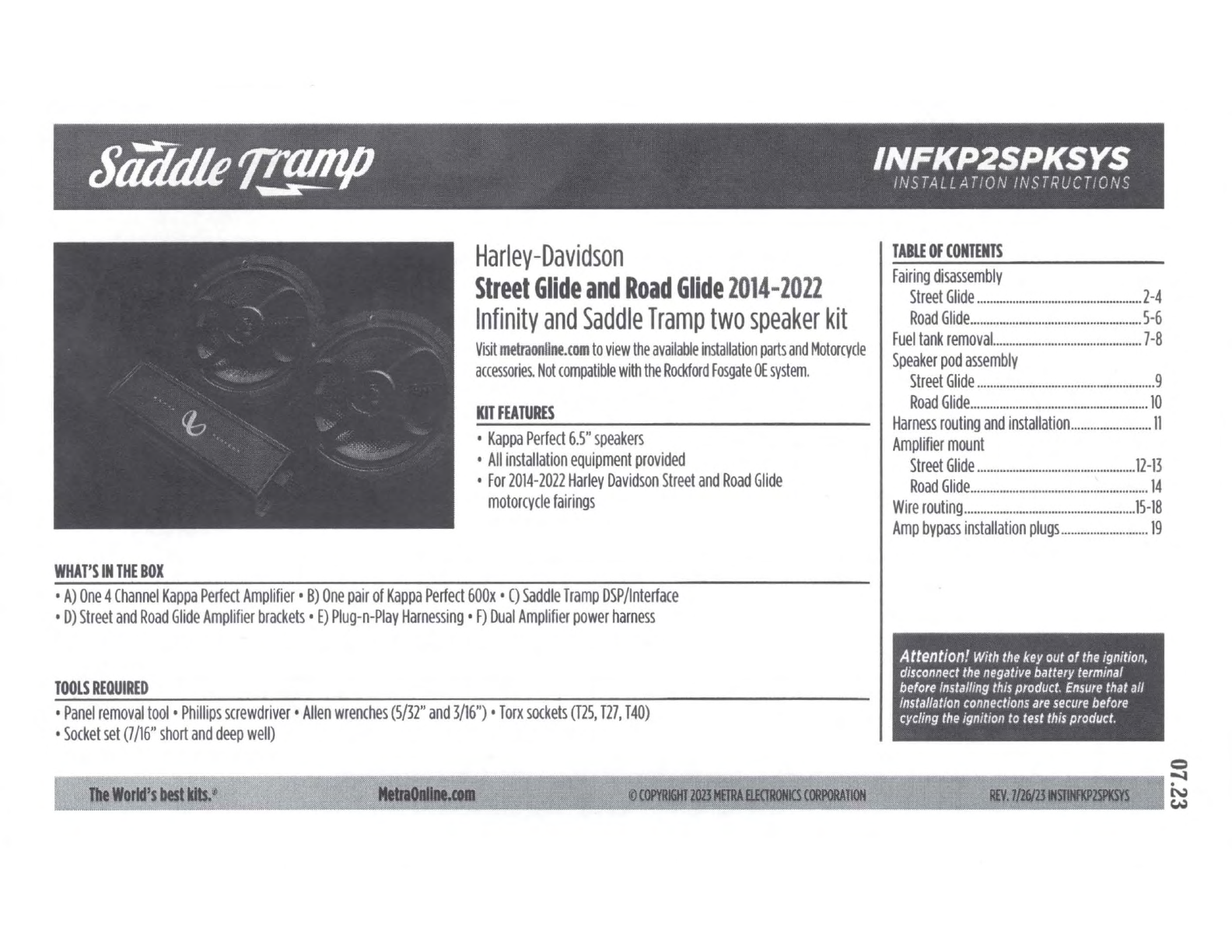
A)
One
4
Channel
Kappa
Perfect
Amplifier•
B)
One
pair
of
Kappa
Perfect
600x
•
C)
Saddle
Tramp
DSP/lnterface
•
D)
Street
and
Road
Glide
Amplifier
brackets
•
E)
Plug
-
n-Play
Harnessing
•
F)
Dual
Amplifier
power
harness
TOOLS
REQUIRED
•
Panel
removal
tool
•
Phillips
screwdriver•
Allen
wrenches
(5/32"
and
3/16")
•
Torx
sockets
(T25,
T27,
T40)
•
Socket
set
(7
/16"
short
and
deep
well)
le
Worlfs
IMst
••
•
~
TABLE
OF
CONTENTS
Fairing
disassembly
Street
Glide
...................................................
2-4
Road
Glide
...........
...
..
.........
.....
..
......
...............
5-6
Fuel
tank
removal...
..
...
..
..
.
...
..
.....
.
..................
....
7-8
Speaker
pod
assembly
Street
Glide
...
..
....
........
....
.
.........
..
.......
.
.........
.
...
.9
Road
Glide
.......................................................
10
Harness
routing
and
installation
..........
.
.............
.
11
Amplifier
mount
Street
Glide
...........
.
..
........
....
......
..........
.......
12-13
Road
Glide
.
...
..
..............................................
...
14
Wire
routing
.
.....
.
....
..
...
...........
....
............
..........
15-18
Amp
bypass
installation
plugs
..
...
.
..
.............
..
....
19
Attention!
With
the
key
out
of
the
ignition,
disconnect
the
negative
battery
terminal
before
Installing
this
product.
Ensure
that all
lnstallatlon
connections
are
secure
before
cycling
the
ignition
to
test
this
product.
Q
~~~~~~~t":::'11
~
N
~