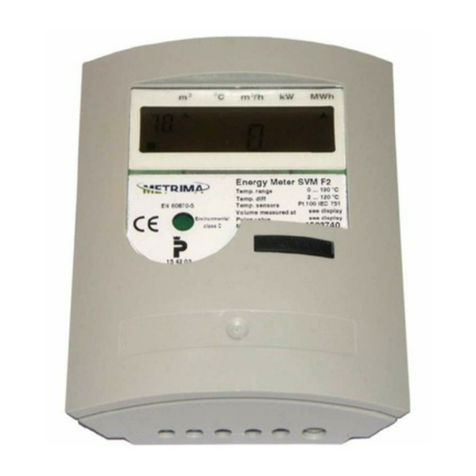
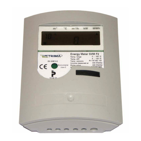
Metrima SVM F4 User manual

SVM F4
Calculator
Manual

2
Calculator F4
manual
1 GENERAL 4
1.1 Installation 4
1.2 Principle of energy measurement 5
1.2.1 Alternative naming 5
1.3 Calculator specifics 5
1.3.1 Monthly values 7
1.3.2 Account days 7
1.3.3 Pulse counter register 1 and 2 8
1.3.4 Placing of flow sensor 8
1.3.5 M-Bus 8
1.3.6 Communication address 8
1.3.7 Power cut 8
2 BUTTONS AND JUMPERS 9
2.1 Push button 9
2.2 Service buttons 9
2.3 Test button 9
2.4 Save data button 9
2.5 2/4-Wire method temperature sensors
jumpers 10
2.6 ON/OFF jumper battery powered
calculators ONLY 10
2.7 Slot jumpers Signal/Power
redirecting 10
2.8 Power ON/OFF 10
3 DISPLAY 11
3.1 Back-light 11
3.2 Display test 11
3.3 Display modes 12
3.3.1 Transport mode 12
3.3.2 Initial mode ( INIT mode) 12
3.3.3. Service Mode 13
3.3.3.1 Service/INIT mode sequence 13
3.3.4 Test mode ( programming mode) 14
3.3.5 Normal mode ( operating mode ) 15
3.3.5.1 Display sequence normal mode 16
3.3.5.2 Display seq. normal mode 2 17
3.3.5.3 Display sequence normal mode
(summary) 17
3.3.5.4 Display sequence normal mode
schematics 18
3.4 Error codes 19
4 SEALS, CALCULATOR
PROTECTION 20
4.1 Volume check 20
5 CONNECTING THE
CALCULATOR / HANDLING 21
5.1 Circuit board F4 21
5.2 Connection terminals 22
5.2.1 Sensors and M-Bus connection 22
5.2.1.1 EN1434 terminal table 22
5.2.2 Pulse input connection 23
5.2.3 Pulse output connection 23
5.2.4 Connection 3V/12V 23
5.2.5 Save data 24
5.2.6 Alarm output connection 24
5.2.7 Option board connection 24
5.2.8 Potential free output 24

3
5.3 Battery and mains connection 25
5.4 Calculator connection 25
5.5 Mains connection and backup
battery 25
5.6 Option board handling 26
5.6.1 Option board installation
procedure 26
5.6.1.1 Installing several option
boards at the same time 26
5.6.2 DIP-Switch setting of option board 27
5.6.3 Installing additional option boards
when one or several option boards
is/are installed 27
5.6.4 Configure the option board 27
5.6.5 Reconfigure option boards 27
5.6.6 Uninstall, removal of option boards or
reconfiguring option boards 27
5.7 Cable fittings 28
5.8 Mounting 28
5.9 Zero sequence current 29
5.9.1 Description of zero sequence
current 29
6 METER MEASURING
6.1 Calculation of flow 30
6.1.1 Momentary flow 30
6.2 Calculation of power 31
6.3 Temperature measurement and
4-wire measurement 31
6.4 Storing values 31
7 TESTING, PROGRAMMING &
SERVICE 32
7.1 Programming the calculator 32
7.2 Display test 32
7.3 Installation test 32
7.4 Service 33
7.4.0 Time 33
7.4.1 Date 33
7.4.2 Pulse value 33
7.4.4 Account days 33
7.4.6 Communication address
(primary address) 33
7.4.7 Resetting stored error time 33
7.4.8 Placement of flow sensor placing33
7.4.9 Recommended date for battery
replacement 33
7.4.A Return to normal mode 33
7.4.10 Clarifications on format 33
7.5 Verifying the calculator 34
8 TECHNICAL DATA 35
8.1 Data output table 35
8.2 Power supply 36
8.3 Temperature sensors 36
8.4 Flow sensors 36
8.5 Temperature ranges 36
8.6 Ambient temperature &
Temperature class 36
8.7 Flow sensor placing 36
8.8 Maximum values for power 36
8.9 Dynamic behaviour 36
8.10 Data output interfaces 36
8.11 Pulse outputs 37
8.12 Pulse inputs 37
8.13 Alarm output 37

4
1 General
1.1 Installation
The calculator is delivered set in “Transport mode”,
but depending on delivery options the calculator
can be delivered in other “display modes”, e.g.
“Transport mode”, see display modes for more
information. Follow this procedure to install the
calculator:
1. Setting of calculator, see “Service, setting
meter” for more information.
2. Install option boards, see “Install option
boards” for more information.
3. To mount the calculator, see “Mounting”.
4. Connecting the calculator, see “Connections”.
5. Check Seal, see “Seals”.
6. Display and function test, see “Display and
function tests”.
7. Set the calculator into normal mode, see
“Different display modes” for more
information.
8. Function test, see “Tests”

5
1.2 Principle of energy
measurement
Energy measurement consists of:
1. Calculator
2. Two paired temperature sensors, resistance
thermometers, PT100 or PT500
3. Flow sensor, that emits pulses
The calculator calculates energy by measuring
temperature difference at each flow pulse emitted
by the flow sensor, or at the sum of several pulses.
Data stored in calculator can be read on the display
or through an external communication. M-Bus is
the standard communication protocol. Other
communication protocols are available on option
boards.
1.2.1 Alternative naming
The nomenclature for the energy industries are not
unified, different words are used to explain the
same things. The words recommended are under-
lined.
Calculator,Heat meter or meter
Flow sensor:
Supply, forward, hot and high.
Return, cold, low
1.2.2 Medium
The F4 calculator algorithm is only for measuring
energy in water.
When using water mixtures another algorithm is
required then the calculator MF4, a calculator for
mixtures is required.
Fig. 1.1, Principle of energy measurement
ABB
F4
1
Supply
2
Return
3
2
SVM

6
1.2.3 Operating conditions
All electronics have limitations like response time,
in memory capacity and so on. In order for the
battery consumption and for trouble free usage of
the calculator following limitations apply for the
F4, see below.
1.2.3.1 Normal operating conditions
for battery supplied calculators
The usage of the calculator is different. In order for
the battery life expectancy to be valid, following
definition of normal operating condition, limits
where one can use the calculator:
M-Bus telegram reading (all protocols) maximum
once per day. High frequency usage of M-Bus
reading reduces battery life.
Only one option board can be installed in the
calculator. When more boards are required and
installed the battery life expectancy will be
reduced. E.g. one option board 10 years, two option
boards 6 years. Note: Not every option board can
be used in a battery supplied calculator, see the
option board documentation for more information.
Flow sensor pulses emitted at the average rate of
maximum 1,5 p/min and with the maximum
temperature difference at 50 degrees K. The
average shall be based on the whole lifetime of the
battery. The calculator shall also have standard
decimal setting, see standard decimal setting
Appendix, A1.
Configuration by using the “FlexServ program”
wrongly can seriously reduce battery life
expectancy on the calculator. Use factory settings
when possible, the settings in which the calculator
was delivered from factory.
Calculator must be set in normal mode (sequence
“10” on display) when using the calculator for
measuring, see also 3.3.5 normal mode. Service-
/Init-/Test-mode reduces battery lifetime expect-
ancy when the calculator is set in these modes for
longer periods of time.
1.2.3.2 Limitations mains supplied
The M-Bus reading frequency must not exceed
once every 20 min. When the reading frequency
exceed this interval the calculator must be equipped
with “galvanic separation board” (FCR2-M1A, for
slot A).

7
1.3 Calculator specifics
The calculator also stores additional data, besides
recorded and calculated values. The calculator
specifics are explained below.
1.3.1 Monthly values
The calculator has up to 37 monthly registers. In
these registers monthly values are stored at then
end of each month. The monthly value is a snap
shot of values at the end of the month. The values
are: oWhen values are stored
oAccumulated energy
oVolume, according to flow sensor
oVolume, according to energy calculation
oEnergy
oAccumulated volume form pulse 1
oAccumulated volume from pulse 2
oPossible error code, at the time of storage
When the maximum number of monthly values is
reached normally 37 values, the calculator replaces
the “oldest” value with a new.
The monthly values can be read in the display and
over the M-Bus the calculator. The order of
presentation is the “newest” value first and then the
previously stored value will be presented and so on.
The number of monthly values can be changed by
using the “FlexServ version 2”. Note: Only by
authorized personnel from Metrima AB.
See also 3.3.5.1 table 3.2 for more information on
sequence 40.
1.3.2 Account days
Some utility companies prefer to read all their
meters at the same time twice a year, at two
predicated days (specific dates) also called account
days.
The F4 has the possibility to store two account
days. The user can specify when these dates are
using service mode or the “FlexServ program”.
Values stored in the account days register are the
same set of values as for monthly register, see
monthly values 1.3.1. Account day is default set to:
Account day 1: 1 January (0101)
Account day 2: 1 July (0701)
The values for the account day will be stored at the
day shift. E.g. Calculator will store the account day
values at 00:00, 1:st of January and at 00:00, .1:st
of July each year.
The “newest” value will be presented first and then
the previously stored value and so on. The “old”
account day values will be replaced when “new
ones” are to be stored. See also 3.3.5.1 table 3.2 for
more information on sequence 30.
Account days can only be changed by the
“FlexServ program version 2”. Note: Only by
authorized personnel from Metrima AB.

8
1.3.3 Pulse counter register 1 and 2
The calculator has two (2) pulse inputs that acts as
volume accumulators in [m³]. To set the volume
accumulators to pulse counters the pulse weight in
calculator must be set to:
1000 [l/p], 0 decimals
Example: 1000 [l/p], 0 decimals -1 m³ per pulse
(One pulse one increment of display). See also
3.3.5.1 table 3.2 for more information on sequence
13 and 14.
1.3.4 Placing of flow sensor
The calculator uses different algorithms to calculate
the energy depending on which pipe (hot or cold)
the flow sensor is placed. Always set the flow
sensor placing correctly in the calculator.
Recommended flow sensor placing is in the return
(cold) pipes, see also fig 1.1, 1.2 principle of energy
measurement, as this side normally is the “cooler
side” for the flow sensor.
The flow sensor placing can be set in the “service
mode”, see Service 7.4 or by using the “FlexServ
program” version 2 or higher.
See also 3.3.5.1 and table 3.2 for more information
on sequence 64, flow sensor placing.
1.3.5 M-Bus
The F2/3/4 calculator is equipped with M-Bus
communication. The M-Bus in the calculator is
according to M-Bus standard and the recommen-
dation according to M-Bus user group.
Battery powered calculators are sensitive and may
not be connected into loops with more than 250 M-
Bus nodes with maximum one M-Bus read once a
day, otherwise the battery life expectancy in the
calculator will be affected.
Extreme M-Bus communication, when the
calculator is flooded by the M-Bus, the calculator
will prioritize the M-Bus over the display. This
flooding will result in strange calculator display
behaviour.
Flooding of the M-Bus communication will not
affect the calculator readings.
1.3.6 Communication address
The calculator has two (2) communication add-
resses in M-Bus.
Primary address, this is a value from 1-250. The
primary address can be changed in the “service
mode”, see also service 7.4 or by using the
“FlexServ program” version 2 or higher.
When two or more meters within a M-Bus loop use
the same primary address a communication coll-
ision will occur. The primary address must be
unique for each calculator in the M-Bus loop.
“Secondary address”, is normally set to F4 serial
number (S/N).
When two or more calculators in an M-Bus loop
use the same primary address a communication
collision will occur. This is why secondary
addressing is recommended when no calculator has
the same secondary address from factory.
In most M-Bus reading programs the user can
choose to address the calculator by the primary or
secondary address. The transfer and communication
speed for the calculator will not be affected by
choosing the primary or the secondary addressing
in M-Bus.
1.3.7 Power cut
Mains powered
When the mains power is cut the calculator will run
following sequence:
1. Automatically switch over to the backup
battery.
2. Store calculator data to an EEProm.
3. Generate an error code “0000080” on display
sequence 15. See also Error Codes, 3.4 (Only
when selected in the calculator programming).
The F4 calculator has a backup battery (both mains
and battery driven calculators). This battery will
supply the calculator with power when main power
is cut. The backup battery will last up to 10 years at
normal usage of calculator, maximum one M-Bus
reading per day and normal energy values.
When power fails, the calculator stores all data to
the EEProm at dayshift. When power is cut from
both mains and backup battery and the calculator
looses all recorded data in temporary memory,
there are two (2) cases:
1. All data stored after dayshift will be lost, see
also storing values, 6.4
2. All data stored after the save by short circuit
the “Save data button” will be lost, see also 2.4
Save data button. Only when the “save data
button” is short circuit after a dayshift.

9
2.3b, Error code displayed when data is saved.
Fig 2.3, Test key
2 Buttons and jumpers
2.1 Push button
The calculator is equipped with a “Push button”.
With the “Push button” the user can toggle between
different values on the display at the display
sequence the calculator is in at the moment. The
user can also use the button to in enter different
display sequences by holding the button until the
calculator shift sequence. There are two ways to use
the “Push button”,
1. Push, e.g. press (and release) to toggle
between different values in the display seq-
uence, see “Display” for more information.
2. Hold, e.g. hold Push button and hold it pressed
until the display changes display sequence, see
“Display” for more information.
2.2 Service button
The service button is used in combination with
holding the “Push button” to enter service mode,
see also “Service mode 3.3.3”.
Tool: Screwdriver or any other suitable dull object.
To enter (or exit) service mode, hold the service
button (carefully) pressed using a small screwdriver
and then hold the “Push button” pressed a few
seconds (5s), then release the “Push button” and
then release the screwdriver. The display sequence
changes to “01” (or back to “10”). For more
information, see “Display 3” for more information.
2.3 Test button
This button is used in combination with holding the
“Push button” to set calculator into test mode.
Tool: Test key
(Rubber key with a leading top)
Enter test mode, hold test button
using “Test key” and then hold
the “Push button” pressed in for
approximately five (5) seconds
then release the “Push button”
and then release the rubber key.
A flash will appear on the display
to indicate the test mode.
Exit test mode, by using the same procedure as
entering the “test mode”, see above, the flash will
disappear after exiting the test mode.
Note: only to be used by authorized personnel
2.4 Save data button
The save data button is used when saving data is
necessary, when changing batteries or when
installing option boards.
When the “Save data button” is short circuited, the
calculator makes readings and saves all data from
temporary memory to the calculator EEPROM.
Note: Data from option boards will not be saved.
Tool:Test key
(Rubber key with a leading
top to short circuit buttons.)
To save, use the “Test key”
and short circuit the “Save
data button” the calculator
will store all temporary data
to the EEPROM.
Check “save data” procedure:
The calculator will display an error code when data
is properly saved. Prior to “save” change the
display sequence to number 15. Then short circuit
the “Save data button” using a “Test key”, the code
“0000080” will be displayed and confirm data
storage, see also Error codes 3.4.
Service button
Test button
Fig 2.2, Location of service and test buttons
Fig 2.4, Save data button
Pu
sh button
Fig 2.1, Push button

10
Fig 2.5, 2/4
-
Wire jum
p
ers
Fig. 2.6, ON/OFF jumper,
OFF, no jumper
2.5 Jumpers 2/4-Wire method
for temperature sensors
The F4 is by default configured for 2-wire
measuring method connection for temperature
sensors. The calculator allows 4-wire measuring
method, by removal of jumpers, see fig 2.5.
4-wire
connection,
remove jumpers
J1, J2, J3 and J4.
2-wire
connection, place
jumpers J1, J2, J3
and J4.
Note: the jumpers
must be placed
according to fig 2.5.
Note: Wrongly placed jumpers can damage the
calculator.
2.6 ON/OFF jumper battery
powered calculators
ONLY
Some F4 is equipped with an ON/OFF jumper this
jumper should be used for battery powered
calculators only.
Note: When cutting the power to the calculator, e.g.
setting calculator “Power OFF” remove the “K2”
then “K3”. See also Power ON/OFF 2.8 below.
Note: ON/OFF jumper only applicable on calculat-
ors powered with batteries. To cut power from
mains supplied calculator see fig 5.1, Circuit board
5.1 and Power ON/OFF.
Power off, no jumper
Power on, jumper on
To cut power from
mains supplied
calculator see fig. 5.1,
Circuit board 5.1 or
2.8 Power ON/OFF.
WARNING: The ON/OFF jumper will not set a
mains powered calculator into “pow-
er OFF” mode. When installing opti-
on boards in a “mains powered” cal-
culator this operation (ON/OFF jum-
per) will only damage the option
board and the calculator.
2.7 Slot jumpers
Signal/Power redirecting
On the slots “C” and “D” there are jumpers for
redirecting power and bus signals. When these are
removed without placing a correct option board in
to the slot, the signals from the calculator can be
disturbed and the calculator’s pulse output and
alarm output can be disabled depending on which
jumper that is wrongly removed.
2.8 Power ON/OFF
For power off cut the power to the calculator by
removing the 4-pole connector “K2” and then
“K3”. Recommended procedure:
Power OFF:
1. Save data, short circuit
“Save data button” (avoid
loosing any data).
2. Remove K2 (main)
3. Remove K3 (backup)
Power ON:
1. Connect K3 (backup)
2. Connect K2 (main)
Fig 2.7, Slot jumpers on slot C and slot D
Fig. 2.7, Power off

11
3 Display
The F2/3/4 calculators are equipped with a LCD
(Liquid crystal display). The units on display label
and decimal placing is different depending on
calculator configuration. See also clarification of
display fig. 3.1:
1. Display sequence, in this case “10”, default
position, (the position the calculator returns to
after 60 seconds of “push-button” inactivity).
The digit “1” displays the sequence and the “0”
displays the order in the sequence. The digits
together form the display sequence “10”, see
also fig. 3.1b (below).
2. Sensor pulse indicator square, indicates a flow
pulse emitted from flow sensor. The square can
also indicate that an error has been detected.
At error (revers to normal); the square will
appear as long as the calculator do not receive
pulse, and disapear when receiving a pulse.
At High frequency (2Hz or more); The square
will appear steadily and disappear on error.
3. Value, max. seven (7) digits
4. Value unit indicator arrow, the triangle points
on the correct unit on the display label for the
unit. (Only when the calculator is correctly
set).
5. Different units on display label, depends on
ordering configuration of calculator.
6. Decimal placing.
Note: the digits after the decimalplacing
“blinks” only in sequence “10” in accordance
with EN1434, according to the standard the
decimals on the display must be clearly
marked.
3.1 Back-light
The calculator display can be equipped with a
“back-light” function. The “back-light” will light
up the display each time the “Push button” is
pressed, and will be turned off one minute after
“Push button” inactivity.
In the display modes Service/INIT/Test mode the
light will light steadily. Avoid setting a calculator
equipped with “back-light” in these modes for
longer periods (10min.). Do not set the calculator
into these modes during transport otherwise the
backup battery life span will seriously be reduced.
During transport and temporarily storage of the
calculator the “Transport mode” mode is to prefer,
in this mode the “back-light” is off. See display
modes, 3.3 for information about display modes.
Note: The “back-light” function consumes more
energy than a calculator without “back-
light” function. Battery powered calcul-
ators (powered with only batteries) should
not be equipped with the “back-light”
function.
3.2 Display test
In accordance with EN1434 all calculators must
have display test. For F2/3/4 the display test is on
sequence 12.
mC
m/h
kW
MWh
3 3
10
1
2
5
4
3
6
Fig 3.1, Display, m
3
, C…
Fig 3.1b, sequence number, value
number together form display
sequence.
Sequence number
Value number
Fig. 3.2, Display test

12
3.3 Display modes
The calculator can be set in different display modes
depending on what data that shall be accessed in the
calculator. To enter the different modes the seals
must be broken and a recommended tool should be
used, see below. The calculator is normally
delivered in “Transport mode”. Depending on
programming the calculator can be delivered in
other display modes as well.
The sequences in the different display modes can
vary depending on different programming of the
calculator. The display modes are:
1. Transport mode
2. Initiation-mode (INIT-mode) programming
by using “Push button”, see service mode.
3. Service mode, programming by only using
the “Push button”
4. Test mode (test and programming mode), by
using the “service program” version 2 or
higher the calculator can be programmed.
5. Normal mode, operating mode, working
mode.
Note: Avoid setting the calculator into “service/
initial mode” or “testing mode” for longer
time periods (1 hour) otherwise the battery
life length expectancy will be effected.
3.3.1 Transport mode
The calculator normally is delivered in transport
mode. In transport mode the calculator “sleeps”, no
measurements and no communication from or to
the calculator will be preformed. In transport mode
only the system clock and (if any) option board will
be supported with minimum power requirements.
The calculator’s “operating time” (display sequence
50) will be in a stand still.
To exit “Transport mode”, hold “Push button”
pressed (approximately 5 seconds) until the “no”
sign disappears. The display sequence changes to
“00” or “10” depending on calculator settings. In
most settings the calculator enters the INIT-mode.
The INIT-mode is indicated by display sequence
“00” see also initiation mode 3.3.2 for further
information.
Using the “service program” version 2.0 or higher
the calculator can be set in “Transport mode”, only
to be used by authorized personnel.
3.3.2 Initial mode ( INIT mode)
The calculator enters the INIT mode after exiting
the transport mode (this can vary depending on
setting of the calculator). The INIT mode is
indicated by display sequence “00”, see also fig 3.5
above. In the INIT mode some calculators setting
can be altered using the “Push button” prior to an
installation without braking any calculator seals.
See Service/INIT mode display sequence 3.3.3.1.
The calculator’s INIT mode can be identical to its
service mode. In some calculators a few sequences
are missing compared to the service mode
depending on calculator setting. For service/INIT
mode sequence, service mode sequence 3.3.3.1.
In INIT-mode the value digit to be changed will
blink and the display sequence will indicate unit for
the value, see service mode 3.3.3 for more
information.
To change value digit, push “Push button” until
correct value is acquired, see fig 3.5 below.
To change digit “to be changed”, hold “Push
button” until the next value digit starts to blink, see
fig 3.5.
To exit INIT mode without braking any seals
when in INIT mode:
1. Hold “Push button” until display sequence
“0A” appears.
2. Release the “Push button”
3. Press “Push button” once to change the
value digit to “1” (exit INIT mode).
4. Hold “Push button” to exit the INIT mode,
the display sequence should read “10”,
normal mode.
Fig. 3.3, Sequence transport mode
Fig. 3.5, Sequence service or INIT mode
Sequence
Service /
INIT
mode
“Blinking” value digit,
digit to be changed.
Hold “push button” for next
digit to be changed.
Push “push button” to change
the value digit.

13
3.3.3 Service Mode
In service mode the settings of the calculator can be
altered using the “Push button”. The service mode
is indicated by “00” (or “0x”) in the display
sequence. See also service 7.4 for more information
on each service sequence and INIT mode 3.3.2 for
initial mode.
To enter “service mode”, hold the “Service
button” pressed with and screwdriver (or another
dull object) at the same time hold “Push button”
pressed in 1-2 seconds. Then release the “Push
button” and the display sequence will change to
service mode, display sequence “00” (also remove
the screwdriver), see also service buttons 2.2.
To exit “service mode”, the same procedure as
when entering the service mode, see above.
To change value digit, push “Push button” until
correct value digit is acquired.
To change value digit “to be changed”, hold
“Push button” pressed until required value digit
starts to blink. Note: The changed value digit is
changed, only when the next value digit is selected
and starts to blink. E.g. do not exit service mode
when the changed value digit is still blinking.
Ensure that the change has been carried out by the
calculator, by first reaching the next service
sequence (example from “01” to “02”) before
exiting the service mode.
To enter next sequence, hold the “Push button”
until next service sequence appears on display, see
also fig. 3.1b.
To exit Service mode in service sequence “0A”:
1. Hold “Push button” until display sequence
“0A” appears.
2. Release the “Push button”
3. Press “Push button” once to change the
value digit to “1” (exit INIT mode).
4. Hold “Push button” to exit the INIT mode,
the display sequence should read “10”,
normal mode.
3.3.3.1 Service/INIT mode
sequence
Sequence Description, format
00 Time, HHMM
01 Date, YYMMDD
02 Pulse value, 0000-9999
e.g. 2.5l/p is displayed with 2500
03 Pulse value decimal places, 0-4
04 Account days 1, MMDD
05 Account days 2, MMDD
06 Primary communication address set
with three (3) digits,
e.g. “5” is set to “0005”
07 Resetting stored error time,
0 = Reset stored error time (default)
1 = Do not reset error time
08 Flow sensor placing,
0 = installed at low temp.(default)
1 = installed at high temperature
09 Replacement of battery date, YYMMDD
Do not change without consulting
Metrima AB
0A Exit service sequence,
1 = Exit
0 = Return to sequence “00”
Table 3.1, Service display sequence,
HH–Hour, mm-Minutes,
YY-Years, MM-months, DD-Days.
See, “Testing…., Service” for additional information
Note: Values in the service mode may only
be altered by trained professionals.
Note: The display sequences in service mode
may vary depending on calculator
configuration.
Warning: Altering the values in the service mode
can seriously effect on the calculator
performance and can result in wrong
measuring.
Fig. 3.5, Sequence service or INIT mode
Sequence
service /
INIT
mode
“Blinking” value digit,
digit to be changed.
Hold “Push button” for next
digit to be changed.
Push “Push button” to change
the value digit.

14
3.3.4 Test mode
(programming mode)
In the test mode all the calculator parameters can be
configured, with the “service program” version 2.0
or higher. Tests can also be performed on the
calculator, see verifying the calculator 7.5. A flash
on the display will indicate this mode, see fig 3.6.
The calculator also activates the optical interface
and emits high frequent pulses corresponding to the
energy increment. See Service 7.4 for more
information. The M-Bus and the display response
in this mode will be slower and in some cases
disturbed.
Setting calculator into test mode by using the
“test key”, a rubber key with an electric leading
head. Hold the “test key” pressed to short circuit
the “test button” (at the same time), hold the “Push
button” pressed (approximately 1-2 seconds), and
then release the “Push button”. The display will
show a “flash” indicating “test mode”, (remove the
“test key”), see also fig 3.6 (below).
Exit test mode, the same procedure as to “set the
calculator into test mode”, see above. The “flash”
will disappear from the display upon exit.
Energy consumption will be higher in “Test
mode” than in calculator normal operating mode.
Avoid setting the calculator into “Test mode” for
longer period than (>1h) or the battery/backup
battery life length will be seriously reduced.
Only Service program version 2.00 (00-10-09) or
later versions may be used to program F4. With the
service program the calculator can be programmed
(configured). This program is backward compatible
e.g. F3/2 can be programmed with the service
program version 2.00 or higher. See also the
Service program manual for further information.
In the service program:
Read type, the calculator programming is read into
the service program.
Change mode, the display mode is changed.
Change type will erase all previously stored
calculator readout data.
Note 1: Avoid to set the calculator into “Service/
Initial mode” or “Testing mode” for
longer time periods (1 hour), when
battery life length will be affected.
Note 2: Calculators delivered with energy unit
“BTU” and flow unit “USG/min” has
fixed decimal setting.
Warning 1: Changing the programming using the
service program version 2.0 or higher
can seriously affect the calculator
behaviour, such as parameters as
battery life length can be seriously
reduced and measuring will be aff-
ected. Do not use the service program
without proper education or
consulting Metrima AB.
Warning 2: When programming the F4 only use
Service program version 2.0 or high-
er, otherwise the calculator will be
seriously damaged!
Warning 3: When programming the F4 only use
Service program version 2.0 or high-
er, otherwise the calculator will be
seriously damaged!
Fig 3.6, Display in test mode, “flash” in display
Flash

15
3.3.5 Normal mode
( operating mode )
Normal mode is the calculators operating mode. In
this mode the calculator accumulates energy,
calculates and makes measurements. The calculator
can also communicate by using M-Bus or SIOX
protocols (SIOX only with an extra option board).
Display sequences
The first digit from left is the sequence number, see
also fig. 3.1b below. This number announces in
which sequence currently is on display (1 to F).
The second digit from left is the value number and
announces which value is displayed in the specific
sequence. The value numbers loops within each
sequence (there are a few exceptions).
See also, display sequence schematics 3.3.5.4 and
display sequence normal mode 3.3.5.1.
Enter next sequence
Hold the “Push button” to enter next sequence,
release when correct display sequence is reached.
Repeat this procedure to enter next sequence. When
exiting the last display sequence F0 the display will
return to the first display sequence 10.
On exiting the display sequence 30 and 40 the
calculator will return to display sequence 10.
Read values
Press “Push button” to toggle to the next display
value. After the last value in the specific sequence
the first value in this sequence will be displayed
and so on.
Default position
When calculator is set in normal mode the display
will return to the default sequence position after
60s, (the return time can be altered by using the
“Service program 2.0” or higher).
Blinking digits
In accordance with EN1434 the digits after the
decimal places blink.
Unit arrow
An arrow will indicate the correct unit for the
value, the display labels varies depending on
calculator.
Example, calculator delivered with different dis-
play labelling depending on kWh, MWh, GJ or
MBTU to be outputted by the calculator.
Note: When calculator is reprogrammed the
“service program” version 2.0 or higher the
label is not “automatically” changed.
Fig 3.7, Display sequence “10” in nor
mal
(seq. 10 default sequence position).
Fig 3.1b, Sequence number and
value number together form display
sequence.
Sequence number
Value number

16
3.3.5.1 Display sequence normal mode
Table 3.2, Display sequence 10 –70, normal mode
Seq Description
10 Accumulated energy (Default position)
11 Accumulated volume according to flow sensor1
12 Display test, see fig.3.2
13 Accumulated volume for pulse input 1, [m3]
14 Accumulated volume for pulse input 2, [m3]
15 Error code, see Error code
16 Error time, [Minutes]
20 Momentary power
21 Momentary flow
22 High temperature, 0 decimals
23 Low temperature, 0 decimals
24 Temperature difference, 1 decimals
30 Account days2, when values are stored, [YYMMDD]
31 Account days2, Accumulated energy
32 Account days2, Accumulated volume according to flow sensor.
33 Account days2, Accumulated volume according to energy calculation
34 Account days2, Accumulated volume pulse input 1, [m3]
35
Account days2, Accumulated volume pulse input 2, [m3]
36 Possible error code, at time of storage of account days
37 Possible accumulated error time, at the time of storage account days, [Minutes]
3x Following account days registers (loop back)
40 Monthly registers3, date when values are stored, [YYMMDD]
41 Monthly registers3, Accumulated energy
42 Monthly registers3, Accumulated volume according to flow sensor
43 Monthly registers3, Accumulated volume according to energy calculation
44 Monthly registers3, Accumulated volume pulse input 1, [m3]
45 Monthly registers3, Accumulated volume pulse input 2, [m3]
46 Possible error code, at time of storage of monthly register
47 Possible accumulated error time, at the time of storage, [Minutes]
4x Following monthly registers (loop back)
50 Operating time, [Hours]
51 Relevant date, [YYMMDD]
52 Relevant time, [HH.MM]
53 Recommended date for battery replacement, [YYMMDD]
60 Communication address, Primary address
A0 Communication address, Secondary address (normally same as meter S/N)
bx Meter S/N5
63 Pulse value [l/p]
64 Placing of flow sensor, [H/L], L = Low
70 Accumulated volume corresponding to accumulated energy
71 Last remote read accumulated energy
72 Time since latest remote read accumulated energy, [Hours]
73 Accumulated error time, [Minutes]
74 Previous error code
75 Time for previous error code, [Minutes]

17
3.3.5.2 Display seq. normal mode 2
For more information on the sequences:
See also for further information, 0calculator specifics.
___________________________________________________________________________
3.3.5.3 Display sequence normal mode (summary)
10 - Readout values 1 (Power, flow)
20 - Readout values 2 (Temperature, momentary values)
30 - Account days values
40 - Monthly registers
50 - Date registers
60 - Communication, settings
70 - Volume check, error listings
90 - Option board status
A0 -F0 Option board sequences
90 ID Option card A
91 Status option card A
92 ID Option card B
93 Status option card B
94 ID Option card C
95 Status option card C
96 ID Option card D
97 Status option card D
98 ID Option card E
99 Status option card E
9A ID Option card F4
9b Status option card F4
A0 Sequence option card A
b0 Sequence option card B
C0 Sequence option card C
d0 Sequence option card D
E0 Sequence option card E
F0 Sequence option card F4
Table 3.2b, Display sequence normal mode
1F2/F3/F4 have two registers for accumulated volume. Value 11, is incremented at the
rate of arrived flow pulses. The other register, value 70 is incremented in
conjunction with energy calculation.
2In order to change to the next account day, keep pushing the button until the date
starts to increment, then release the button. After the display 37, see table above,
the next account day will display. Note: If one hold the “Push button” again the
display reverts to default position (seq. 10).
3To change to another month keep pushing the button until the date starts to
increment. Release at the requisite month. After display 47, see above, the next
stored date will be displayed. Note: If one hold the “Push button” again the display
reverts to default position ( seq. 10).
4This sequence’s slot is only available in the F2, but will also be displayed in the
F4. The F4 has maximum 5 slots.
5The second digit form left in the sequence “bx” (e.g. x) will marke the most
significant digit in the calculator serialnumber. Example: Calculator serialnumber is
“0000 0015” the sequence will display “b0”, and if the seraialnumber is “8000 0015”
the sequece will display “b8”.

18
3.3.5.4 Display sequence normal mode schematics
Fig 3.8, Display schematics for “normal mode”
One (1) Option
board selected
six (6) Option
board selected
10
20
30
40
50
60
70
90
A0
b0
Only when option
board are selected
Loop back to next
monthly register
Loop to next
account day
Default
position
C0
d0
E0
F0*
How to:
To change sequence HOLD the
“Push button” until the display
changes sequence.
To change values within a specific
sequence PUSH “Push button” until
the display changes value.
*
Only in F2. No such option board slot in F4 but will be displayed in
the display sequence.

19
3.4 Error codes
Sometimes an error code will appear in display sequence 15, 37, 47, 74 and on M-Bus.
The error code message can be interpreted using the table below. The error codes consist
of three (3) hexadecimal (Hex) digits, e.g. 0 –15. Each digit can have up to 4 different
error codes in combination. The correct error code can be acquired by combining the
digits, see also example below. The digits shall be read from the right to the left.
Example: 0000005 = 1 + 4 = error 1 and error 4, low temperature sensor disconnected
and high temperature sensors disconnected.
1 Low temp. sensor disconnected
2 Low temp. sensor short circuit
4 High temp. sensor disconnected
Display
digit 1
first
( from
right ) 8 High temp. sensor short circuit
1
Internal bus collision has occurred within
24 hours.
2 I²C error ( internal bus error )
4 Low flow
Display
digit 2
second
( from
right ) 8 Alarm input, low voltage*
1 Battery expire
2 Oscillator error
4 Pulse input too long
Display
digit 3
third
( from
right) 8 Not in use
Table 3.3, Error code numbers
A good help to is use the table below to find out which error the calculator displays
Example: 00000045
First digit 5 from right = Error code 4 + Error code 1 = Temperature sensors (low+high) disconnected
Second digit 4 from right = Error code 4 = Low Flow Error
*“0000080”,can vary depending on setting in the
calculator.
1. No voltage (default value), the calculator will
show this error code when there is no power
supplied from the mains.
2. External alarm set, alarm from an external device.
This error code will also appear when the “Save
data button” is short circuited, see also 2.4, Save
data button.
No.
Hex. Dec. Error
number(s)
0 0 0
1 1 1
2 2 2
3 3 1 + 2
4 4 4
5 5 4 + 1
6 6 4 + 2
7 7 4 + 2 + 1
8 8 8
9 9 8 + 1
A 10 8 + 2
B 11 8 + 2 + 1
C 12 8 + 4
D 13 8 + 4 + 1
E 14 8 + 4 + 2
F 15 8 + 4 + 2 + 1
Table 3.3b, Error hex decoding key
mC
m/h
KW
Mwh
3 3
Fig 3.10, error at display sequence “15”
first digit “5”, second digit “4”
First digit
Second digit
Third digit

20
4 Seals, calculator
protection
The F2/3/4 are tampering protected with seals. To
enter the calculator or to enter “Test mode”,
“Service mode” or to enter the electronics inside
the calculator several seals need to be broken, see
placement of the seals below:
4.1 Volume check
The F2/3/4 have an extra volume check, e.g. the
calculator has two different accumulated volume
registers:
Volume accumulated from flow sensor
(Display sequence 11)
Volume accumulated from energy calcula-
tion, e.g. calculated from increment register.
(Display sequence 70)
This function prevents tampering of flow pulses
programmed in meter and acts as an extra check.
Normally there is a small difference between these
two registers.
Seals
1. Installation seal, installation and tampering
protection.
2. Service seal, to protect the calculator entering
the service mode.
3. Test seal, to protect the calculator entering and
program the calculator.
4. Factory seal, the electronics protection
4.2 Neutral seals
With every delivery of the F2/3/4 four neutral seals
are included. These neutral seals can be used after
installation.
Fig 4.2, Neutral seals can be used after an installation.
4
1
2
3
Fig 4.1, Placement of seals F3/F4
4
3
2
Fig 4.1, F2 Placement of seals
Table of contents
Other Metrima Calculator manuals
Popular Calculator manuals by other brands
Sentry
Sentry CA338 user guide
Casio
Casio CFX-9850G PLUS Calculations guide

Texas Instruments
Texas Instruments TI36X - Solar Scientific Calculator user guide
Texas Instruments
Texas Instruments TI-83 Plus Silver Edition manual
Citizen
Citizen SDC-9008N instruction manual
Sharp
Sharp Elsi Mate EL-331A Operation manual
