METRObility Optical Systems RADIANCE Series Operation manual

Installation & User Guide
Models: R131-13 / R131-14 / R131-15 / R131-16 / R131-17 / R131-1J /
R131-1X / R131-1Y / R131-33 / R131-34 / R131-36 / R131-44 /
R131-47 / R131-4J / R131-54 / R131-55 / R131-56 / R131-66 /
R131-77 / R131-JJ / R133-13 / R133-14 / R133-15 / R133-16 /
R133-17 / R133-1E / R133-1J / R133-1K / R133-1M / R133-1X /
R133-1Y
RADIANCE 100MBPS
SINGLE INTERFACE LINE CARDS
PWR
LK
LK
M
M
AT
AT
100 BASE
S
M
LK
AT
FX
S
M
PWR
AT
LK
100 BASE
LK
AT
FX
M
M
PWR
LK
AT
T
X
100 BASE
LK
AT
S
M
PWR
LK
AT
100 BASE
PWR
LK
LK
AT
AT
100 BASE
PWR
LK
LK
S
M
S
M
AT
AT
100 BASE
PWR
LK
LK
AT
AT
100 BASE
LK
AT
L
H
PWR
LK
L
H
AT
100 BASE
LK
AT
M
M
PWR
LK
T
XAT
100 BASE
LK
AT
PWR
LK
AT
100 BASE
LK
AT
PWR
LK
AT
100 BASE
R
X
T
X
TX TX
M
M
R
X
T
X
R
X
T
X
S
M
M
M
R
X
T
X
R
X
T
X
R
X
T
X
R
X
T
X
M
M
S
M
R
X
T
X
R
X
T
X
T
X
M
M
R
X
R
X
T
X
T
X
R
X
R
X
T
X
T
X
R
X
R
X
E
L
H
S
M
T
X
T
X
R
X
R
X
M
M
M
M
T
X
T
X
R
X
R
XLK
AT
FX
B
W
D
M
PWR
AT
LK
100 BASE
TX
LK
AT
PWR
AT
LK
100 BASE
LK
AT
MM
PWR
LK
AT
T
X
100 BASE
T
X
FD
LB
SM
FD
LB
LK
AT
PWR
LK
AT
T
X
100 BASE
FD
LB

This publication is protected by the copyright laws of the United States and other countries, with all rights
reserved. No part of this publication may be reproduced, stored in a retrieval system, translated,
transcribed, or transmitted, in any form, or by any means manual, electric, electronic, electromagnetic,
mechanical, chemical, optical or otherwise, without prior explicit written permission of Metrobility Optical
Systems, Inc.
© 2001-2004 Metrobility Optical Systems, Inc. All rights reserved. Printed in USA.
Radiance 100Mbps Single Interface Line Cards
Full-Featured Copper to Fiber with LLCF, FEF, Remote Loopback, Auto-
Negotiation, and Auto-Crossover:
R133-13 ___ RJ-45 to FX multimode SC
R133-14 ___ RJ-45 to FX singlemode SC
R133-15 ___ RJ-45 to FX multimode ST
R133-16 ___ RJ-45 to FX singlemode ST
R133-17 ___ RJ-45 to FX singlemode SC (40km)
R133-1E___ RJ-45 to FX multimode MT-RJ
R133-1J ___ RJ-45 to FX singlemode SC (100km)
R133-1K___ RJ-45 to FX multimode LC
R133-1M __ RJ-45 to FX singlemode LC
R133-1X___RJ-45 to FX singlemode SC 1550/1310nm bidirectional
wavelength division multiplexed (BWDM)
R133-1Y___ RJ-45 to FX singlemode SC 1310/1550nm BWDM
Copper to Fiber with LLCF:
R131-13 ___ RJ-45 to FX multimode SC
R131-14 ___ RJ-45 to FX singlemode SC
R131-15 ___ RJ-45 to FX multimode ST
R131-16 ___ RJ-45 to FX singlemode ST
R131-17 ___ RJ-45 to FX singlemode SC (40km)
R131-1J ___ RJ-45 to FX singlemode SC (100km)
R131-1X___ RJ-45 to FX singlemode SC 1550/1310nm BWDM
R131-1Y___ RJ-45 to FX singlemode SC 1310/1550nm BWDM
Fiber to Fiber with LLCF:
R131-33 ___ FX multimode SC to FX multimode SC
R131-34 ___ FX multimode SC to FX singlemode SC
R131-36 ___ FX multimode SC to FX singlemode ST
R131-44 ___ FX singlemode SC to FX singlemode SC
R131-47 ___ FX singlemode SC to FX singlemode SC (40km)
R131-4J ___ FX singlemode SC to FX singlemode SC (100km)
R131-54 ___ FX multimode ST to FX singlemode SC
R131-55 ___ FX multimode ST to FX multimode ST
R131-56 ___ FX multimode ST to FX singlemode ST
R131-66 ___ FX singlemode ST to FX singlemode ST
R131-77 ___ FX singlemode SC (40km) to FX singlemode SC (40km)
R131-JJ ___ FX singlemode SC (100km) to FX singlemode SC (100km)

Table of Contents
Radiance 100Mbps Single Interface Line Cards
Installation & User Guide
Overview..............................................................................................................4
Installation Guide ...............................................................................................5
STEP 1: Unpack the Line Card .............................................................5
STEP 2: Set the Jumper (R131 Only) ...................................................5
STEP 3: Set the MDI-II/MDI-X Switch
(R131-1x twisted-pair ports only) .......................................... 6
STEP 4: Set the DIP Switches (R133 Only) .........................................7
STEP 5: Install the Line Card ............................................................... 9
STEP 6: Connect to the Network ........................................................10
User Guide ........................................................................................................13
LED Indicators ....................................................................................13
Link Loss Carry Forward (LLCF) ......................................................14
Far End Fault (FEF—R133 Only) ......................................................16
Remote Loopback (R133 Only) ..........................................................17
Topology Solutions .............................................................................18
Technical Specifications......................................................................19
Product Safety, EMC and Compliance Statements .............................21
Warranty and Servicing....................................................................... 22
Metrobility, Metrobility Optical Systems, and NetBeacon are trademarks of Metrobility Optical Systems,
Inc. The Metrobility Optical Systems logo is a trademark of Metrobility Optical Systems, Inc. All others
are trademarks of their respective owners.
The information contained in this document is assumed to be correct and current. The manufacturer is
not responsible for errors or omissions and reserves the right to change specifications at any time
without notice.

4
Overview
For updating or expanding an existing network, Metrobility® offers the
Radiance 100Mbps single interface line cards in various combinations including
copper to fiber, multimode to singlemode, and fiber optic distance extension.
Use the optical extender units to increase your network reach up to 100km over
singlemode cables at full duplex without the need for repeaters. These line cards
allow you to maximize your Fast Ethernet segments and transparently transmit
all signal activity for multimode-to-multimode or singlemode-to-singlemode
configurations.
The mixed-media line cards offer seamless integration of copper and fiber connec-
tions in copper-to-fiber networks. This innovative solution provides full signal
restoration ensuring accurate data transmission and guaranteeing maximum cable
length support. All line cards are compatible with any Fast Ethernet device.
Through Metrobility’s unique management functionality, you can manage
remote connections through console commands, our NetBeacon®or WebBeacon
software, or with any standard SNMP application. This end-to-end visibility of
your network not only simplifies network management but also increases
network reliability.
The Radiance 100Mbps line card provides the following key features:
• Fused power on each line card to protect the rest of the cards in the
chassis from a short circuit. The power (PWR) LED on an affected card
will not be lit if its fuse is blown.
• Half and full duplex support.
• Auto polarity support on all twisted-pair ports.
• Link Loss Carry Forward functionality to aid in troubleshooting.
• MDI-II/MDI-X switch on all R131 twisted-pair ports. The R133 provides
built-in crossover to automatically perform the function of the switch.
• On the R133, the copper port supports auto-negotiation and the fiber port
supports both Far End Fault (FEF) and remote loopback.
• Data frame size transparency.
• Numerous connectivity options, including bidirectional wavelength
multiplexed (BWDM) fiber.

Radiance 100Mbps Single Interface Line Cards 5
Installation Guide
Follow the simple steps outlined in this section to install and start using the
Radiance 100Mbps single interface line card.
NOTE: Electrostatic discharge precautions should be taken when handling any
line card. Proper grounding is recommended (i.e., wear a wrist strap).
Unpack the Line Card
Your order has been provided with the safest possible packaging, but
shipping damage does occasionally occur. Inspect your line card
carefully. If you discover any shipping damage, notify your carrier and
follow their instructions for damage and claims. Save the original
shipping carton if return or storage of the unit is necessary.
Set the Jumper (R131 Only)
All Radiance 100Mbps single interface line cards incorporate LLCF
(Link Loss Carry Forward) functionality as an aid in troubleshooting a
remote connection. Ajumper configures LLCF*operation on the R131
models.
Jumper Settings
See the diagram below for the location of the LLCF jumper.
• Connect pins 1 and 2 to enable LLCF.
• Connect pins 2 and 3 to disable LLCF. (default)
*LLCF also can be controlled through console commands or with Metrobility’s NetBeacon or WebBeacon management
software. Refer to the
Command Line Interface Reference Guide, NetBeacon Element Management Software Installation
& User’s Guide
or
WebBeacon Management Software Installation & User’s Guide
for software management information.
LLCF
LLCF
Jumper
3 OFF
2
1 ON
Port 1
Port 2
This is a generalized diagram of a Radiance R131
100Mbps single interface line card and is not specific to
any particular model.
1
2

6 Installation Guide
3
Set the MDI-II/MDI-X Switch
(R131-1x twisted-pair ports only)
To eliminate the need for crossover cables, the R131-1x line card has
an MDI-II to MDI-X slide switch for its twisted-pair port. The switch is
positioned directly behind its associated RJ-45 connector and allows
simple setup in either straight-through (default) or crossover configura-
tions. See the diagram below for the location of the switch.
LLCF
OFF
ON
3
2
1RJ-45
Slide Switch
MDI-X Position
MDI-II Position
(default)
When setting the MDI-II to MDI-Xswitch, observe the positioning of
the following symbols:
• The parallel symbol (II) indicates a straight-through or parallel
connection. (default)
• The cross symbol (X) indicates a crossover connection.
These symbols are clearly marked on the printed circuit board. Simply
slide the switch in the direction of the appropriate symbol. Use the
following table as a guide.
A device that is wired straight through needs one crossover connection:
If the cable is
straight through
crossover
the MDI-II to MDI-X Switch Setting should be
X
II
A device that is wired crossover needs a parallel connection:
If the cable is
straight through
crossover
the MDI-II to MDI-X Switch Setting should be
II
X
Radiance 100Mbps Single Interface Line Cards 7
4
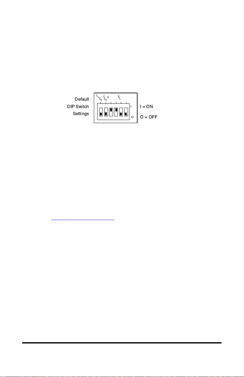
Set the DIP Switches (R133 only)
The R133 provides a set of six DIP switches located on the back of the
board. These switches allow you to select from several modes of
operation. To enable a function, set the switch UP (lever pushed away
from the printed circuit board); to disable a function, set the switch
DOWN (lever pushed toward the circuit board). The default settings are
shown below.
Default
DIP Switch
Settings
I
O
L
L
C
F
I=ON
O = OFF
F
E
F
A
N
1
F
D
1
D
S
L
B
R
L
B
K
Link Loss Carry Forward Switch (LLCF)
The R133 incorporates Link Loss Carry Forward functionality as an aid
in troubleshooting remote connections. When LLCF is enabled, the loss
of inbound link pulses on a port stops the transmission of outbound link
pulses from the opposite port. For example, if LLCF is enabled, the loss
of incoming link pulses at Port 1 will stop the transmission of link
pulses out of Port 2. Conversely, if Port 2 stops receiving link pulses,
Port 1 will not transmit link pulses.
Link Loss Carry Forward is enabled simultaneously on both ports when
switch LLCF is enabled. The unit is shipped with LLCF disabled. Refer
to Link Loss Carry Forward in the User Guide section of this manual
for further details.
Far End Fault Switch (FEF)
The R133 supports Far End Fault functionality to detect the loss of link
by the remote unit’s fiber port receiver.
FEF is only applicable to the fiber port (Port 2). When FEF is enabled
on a port, the loss of the inbound link pulses on that port generates an
alarm, which is sent out the port’s transmitter. FEF also enables a port
to read the alarm. To function properly, the FEF setting on both the
local and remote R133 line cards must be the same.
For example, if FEF is enabled on both line cards and the remote unit’s
fiber receiver (RX) stops detecting link pulses, then its fiber transmitter
(TX) will send an alarm. The local line card will receive the alarm and
report it through its fiber port FEF LED, which will turn amber. No

8 Installation Guide
alarm will be issued if FEF is disabled on the remote card. The FEF
LED will not turn amber if FEF is disabled on the local R133 line card
because it will not be able to detect the alarm.
Far End Fault is enabled on Port 2 when switch FEF is ON. The unit is
shipped with FEF disabled. Refer to Far End Fault in the User Guide
section of this manual for more information.
Auto-Negotiation Switch (AN1)
Switch AN1 controls the use of auto-negotiation on the copper port.
Auto-negotiation determines whether the port operates at half or full
duplex. WhenAN1 is enabled, the copper port advertises full duplex
capabilities to its connected device, if the duplex switch, FD1, is
enabled. The port will advertise half duplex capabilities if FD1 is
disabled. If AN1 is disabled, the duplex switch will determine the port’s
duplex mode. By default, auto-negotiation is enabled.
Duplex Switch (FD1)
Switch FD1 sets the duplex mode for the copper port when auto-
negotiation is disabled. The port operates at full duplex when FD1 is
enabled; and it operates at half duplex when FD1 is disabled. If auto-
negotiation is enabled, the FD1 switch setting will determine whether
the port advertises full or half duplex (refer to Auto-Negotiation above).
The default is set to full duplex enabled.
Copper Port Configuration Table
Use the table below to set the duplex and auto-negotiation DIP
switches to obtain specific modes of operation for the copper port.
noitarugifnoCtroPreppoC1DF1NA
xelpuDlluFNOFFO
xelpuDflaHFFOFFO
xelpuDlluFetaitogeN-otuANONO
xelpuDflaHetaitogeN-otuAFFONO
Disable Loopback Switch (DSLB)
This switch determines the response of the fiber port when it receives
the remote loopback command. If the DSLB switch is enabled, the port
will ignore all remote loopback commands. When the switch is
disabled, the port will permit remote loopback to occur. By default, the
response switch is disabled, which allows remote loopback.

Radiance 100Mbps Single Interface Line Cards 9
Remote Loopback Switch (RLBK)
The remote loopback switch allows you to test the fiber connection
between two Metrobility x133 units. Enabling the switch sends a
loopback request to the remote fiber port. To run the remote loopback
test properly, the following conditions must be met:
• The remote unit must be a Metrobility x133. The remote unit
may be either a standalone converter or line card.
• The DSLB response switch on the remote unit must be disabled.
If the conditions are satisfied, the remote loopback sequence will begin.
The remote fiber port will go into loopback mode. Next, the local card
will generate a test pattern that is sent to the remote unit and then
looped back. The local card will read the returned data to verify proper
transmission. The LB LED on the local card will indicate whether the
test passed (green) or failed (amber). Refer to Remote Loopback for
further information.
If the conditions for remote loopback are not met, the remote loopback
test will always fail. By default, remote loopback is disabled.
Install the Line Card
The Radiance 100Mbps single interface line card offers the ease of
plug-and-play installation and is hot-swappable. The card must be
firmly secured to the chassis before network connections are made.
Follow the simple steps outlined below to install your line card.
• Grasp the card by the front panel as shown.
5
FX
PWR
RX
RX
LK
LK
M
M
FL
TX
TX
10/100
M
M
RX
LK
TX
FX
M
M
II
x
PWR
100 FD
RX
LK
T
X
TX
10/100
II
x
PWR
100 FD
RX
RX
LK
LK
T
X
M
M
FL
TX
TX
10/100
II
x
II
x
PWR
100 FD
100 FD
RX
RX
LK
LK
T
X
T
X
TX
TX
10/100
RX
LK
TX
FX
M
M
II
x
PWR
100 FD
RX
LK
T
X
TX
10/100
MGT-10
LK
AT
C
O
N
S
O
L
E
T
P
PWR
A
B
R
ER
FX
PWR
RX
RX
LK
LK
M
M
FL
TX
TX
10/100
M
M
PWR
RX
RX
LK
LK
M
M
FL
TX
TX
10/100
FX
M
M
PWR
M
M
OC-12
R
XLK
LK
T
X
S
M
R
X
T
X
LX
LK
LK
PWR
1000BASE
S
M
SX
M
M
PWR
1000BASE
LK
LK
SX
M
M
LX
S
M
R
X
T
X
Card Guide
Card Guide Slot for Management Card
Thumb Screw
Blank Panel
IMPORTANT!
Tighten thumb screw
to secure each card firmly
to chassis before making
network connections.
FX
PWR
RX
RX
LK
LK
M
M
FL
TX
TX
10/100
M
M
FX
PWR
RX
RX
LK
LK
M
M
FL
TX
TX
10/100
M
M
PWR
M
M
OC-12
R
XLK
LK
T
X
S
M
R
X
T
X
PWR
M
M
OC-12
R
XLK
LK
T
X
S
M
R
X
T
X
PWR
M
M
OC-12
R
XLK
LK
T
X
S
M
R
X
T
X
PWR
M
M
OC-12
R
XLK
LK
T
X
S
M
R
X
T
X
R
X
T
X
LK
PWR
100 BASE
AT
R
X
TX
LK
AT
T
X
FX
10 Installation Guide
• Insert the card into a slot on the chassis making sure that the top
and bottom edges of the board are aligned with the top and
bottom card guides in the chassis. Do not force the card into the
chassis unnecessarily. It should slide in easily and evenly.
• Slide the card in until the top and bottom edges of the front
panel are flush and even with the top and bottom edges of the
chassis.
• To secure the line card to the chassis, turn the thumbscrew
clockwise until it is snug. The card is now properly installed and
ready for connection to the network.
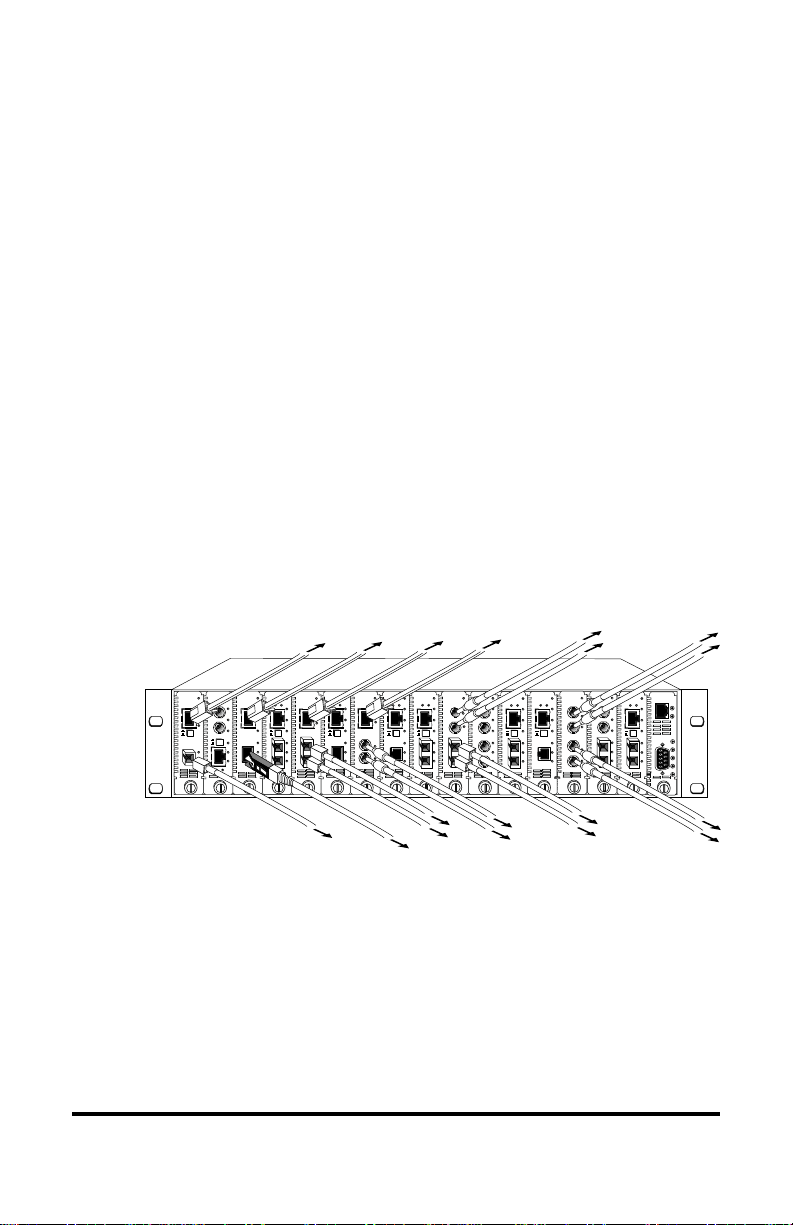
Connect to the Network
To connect the Radiance line card to the network, insert the cables into
the appropriate connectors as illustrated below. Be sure the card is
secured to the chassis before making network connections. Once power
is applied to the unit, correct connectivity can be verified via the LK
(link) LED.
LK
AT
FX
PWR
AT
LK
100 BASE
RX
LK
TX
FX
M
M
II
x
PWR
100 FD
RX
LK
T
X
TX
10/100
RX
LK
TX
FX
M
M
II
x
PWR
100 FD
RX
LK
T
X
TX
10/100
LK
AT
FX
R
X
PWR
FD
RX
100 BASE
II
x
PWR
100 FD
RX
RX
LK
LK
T
X
M
M
FL
TX
TX
10/100
II
x
PWR
RX
LK
B
W
D
MTX
100 BASE
RX
LK
TX
FX
M
M
II
x
PWR
100 FD
RX
LK
T
X
TX
10/100
RX
LK
TX
FX
M
M
II
x
PWR
100 FD
RX
LK
T
X
TX
10/100
LK
AT
LB
PWR
LK
AT
T
X
FD
100 BASE MGT-10
LK
AT
C
O
N
S
O
L
E
T
P
PWR
A
B
R
ER
FX
PWR
RX
RX
LK
LK
M
M
FL
TX
TX
10/100
M
M
PWR
RX
R
X
LK
AT
M
M
TX
T
X
100 BASE
S
M
RX
LK
TX
FX
M
M
II
x
PWR
100 FD
RX
LK
T
X
TX
10/100
RX
LK
TX
FX
M
M
II
x
PWR
100 FD
RX
LK
T
X
TX
10/100
PWR
R
X
LK
LK
M
M
T
X
100 BASE
PWR
RX
RX
LK
LK
M
M
FL
TX
TX
10/100
FX
M
M
RX
LK
TX
FX
M
M
II
x
PWR
100 FD
RX
LK
T
X
TX
10/100
R
X
T
X
LK
TX
T
X
TX
R
X
T
X
M
MS
M
R
X
M
M
T
X
AT
AT
TX
Twisted-Pair Interfaces
All twisted-pair ports provide a shielded RJ-45 connector that supports
a maximum segment length of 100 meters. Use only Category 5 cables.
Fiber Optic Interfaces
When making network connections, make sure that the transmit (TX)
port of the card connects to the receive (RX) port of the connected
device. Be sure that the transmit (TX) port of the connected device
connects to the receive (RX) port of the card.
6

Radiance 100Mbps Single Interface Line Cards 11
All multimode (MM) fiber optic interfaces support a maximum
segment length of 2km for remote links.
The singlemode (SM) interface supports a maximum segment length of
20km, 40km, or 100km. Refer to the Network Connections list below
for the maximum cable length supported by each model number.
BWDM Interfaces
The bidirectional wavelength division multiplexed (BWDM) port
provides one singlemode SC connector that supports a maximum
segment length of 20km. BWDM line cards must always be used in
complementary pairs. That is, a -1X model must always be connected
to a -1Y. The -1X cards are designed to transmit data at a wavelength of
1550nm and receive at 1310nm. Correspondingly, the -1Y cards
transmit data at 1310nm and receive at 1550nm.
Network Connections
TX-to-FX: Max Distance
R131-13 RJ-45 to FX multimode SC _________________ 100m/2km
R131-14 RJ-45 to FX singlemode SC________________ 100m/20km
R131-15 RJ-45 to FX multimode ST _________________ 100m/2km
R131-16 RJ-45 to FX singlemode ST ________________ 100m/20km
R131-17 RJ-45 to FX singlemode SC________________ 100m/40km
R131-1J RJ-45 to FX singlemode SC _______________ 100m/100km
R131-1X RJ-45 to FX singlemode BWDM SC_________ 100m/20km
R131-1Y RJ-45 to FX singlemode BWDM SC _________ 100m/20km
R133-13 RJ-45 to FX multimode SC _________________ 100m/2km
R133-14 RJ-45 to FX singlemode SC________________ 100m/20km
R133-15 RJ-45 to FX multimode ST _________________ 100m/2km
R133-16 RJ-45 to FX singlemode ST ________________ 100m/20km
R133-17 RJ-45 to FX singlemode SC________________ 100m/40km
R133-1E RJ-45 to FX multimode MT-RJ ______________ 100m/2km
R133-1J RJ-45 to FX singlemode SC _______________ 100m/100km
R133-1K RJ-45 to FX multimode LC_________________ 100m/2km
R133-1M RJ-45 to FX singlemode LC _______________ 100m/20km
R133-1X RJ-45 to FX singlemode BWDM SC_________ 100m/20km
R133-1Y RJ-45 to FX singlemode BWDM SC _________ 100m/20km
MM-to-MM:
R131-33 FX multimode SC to FX multimode SC ________ 2km/2km
R131-55 FX multimode ST to FX multimode ST ________ 2km/2km

12 Installation Guide
MM-to-SM:
R131-34 FX multimode SC to FX singlemode SC _______ 2km/20km
R131-36 FX multimode SC to FX singlemode ST _______ 2km/20km
R131-54 FX multimode ST to FX singlemode SC _______ 2km/20km
R131-56 FX multimode ST to FX singlemode ST _______ 2km/20km
SM-to-SM:
R131-44 FX singlemode SC to FX singlemode SC _____ 20km/20km
R131-47 FX singlemode SC to FX singlemode SC _____ 20km/40km
R131-4J FX singlemode SC to FX singlemode SC ____ 20km/100km
R131-66 FX singlemode ST to FX singlemode ST _____ 20km/20km
R131-77 FX singlemode SC to FX singlemode SC _____ 40km/40km
R131-JJ FX singlemode SC to FX singlemode SC____ 100km/100km

Radiance 100Mbps Single Interface Line Cards 13
User Guide
This section contains information about the operating features of the
Radiance 100Mbps single interface line cards.
LED Indicators
The Radiance 100Mbps single interface line cards provide several LEDs for the
visible verification of unit status and proper functionality. These LEDs can help
with troubleshooting and overall network diagnosis and management. There are
separate activity (AT) and link (LK) indicators for each port. Once power is
applied to the card, verify correct connectivity via the LK LED.
R131 LEDs
DEL lebaL DEL emaN)sutatS(roloC noitacidnI
RWPrewop)ydaets(neerg.NOsitinuehT
KLknil)ydaets(neerg.dehsilbatseknilsahtropehttahtseifireV
TAytivitca)gnihsalf(neerg.atadgniviecersitropehT
DEL lebaL DEL emaN)sutatS(roloC noitacidnI
RWPrewop)ydaets(neerg.NOsitinuehT
sDELtroPreppoC
KLknil)ydaets(neerg.dehsilbatseknilsahtropehttahtseifireV
TAytivitca)gnihsalf(neerg.atadgniviecersitropehT
DFxelpud)ydaets(neerg -flahnisitI.tilnehwedomxelpud-llufnisitropehT .tiltonnehwedomxelpud
sDELtroPrebiF
KLknil )ydaets(neerg.dehsilbatseknilsahtropehttahtseifireV
)ydaets(rebma tonsitroprebifetomerehT.detcetedtluafdneraF .tinulacolehtmorflangisdilavagniviecer
TAytivitca)gnihsalf(neerg.atadgniviecersitropehT
BL etomer kcabpool
)ydaets(neerg ehtnoRO;lufsseccussawtsetkcabpooletomeR .nrettaptsetgniviecersitroprebif,dracetomer
)ydaets(rebma etomerehtnoRO;deliafsahtsetkcabpooletomeR .nrettaptsetgniviecertonsitroprebif,drac
ffo.noitarepolamroN
R133 LEDs

14 User Guide
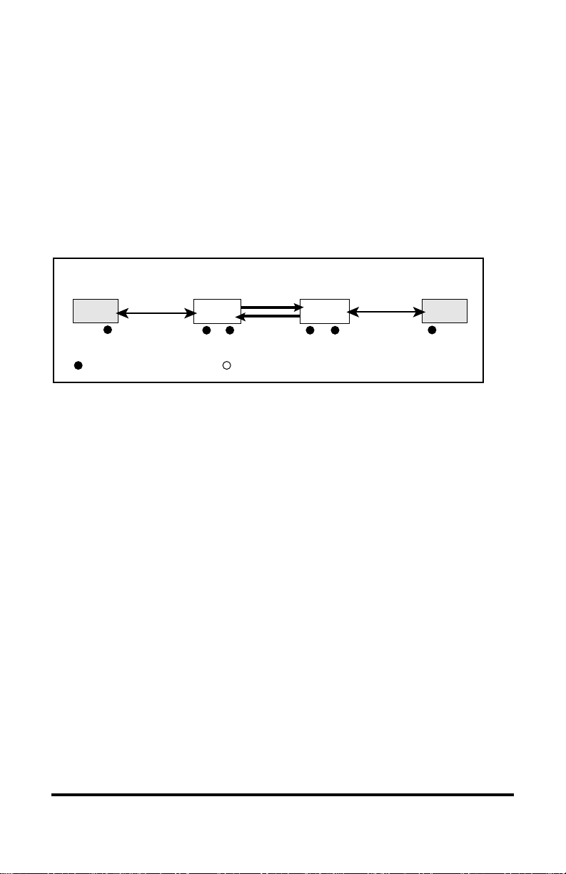
Link Loss Carry Forward (LLCF)*
The Radiance 100Mbps single interface line cards incorporate an LLCF function
for troubleshooting a remote connection. When LLCF is enabled, the ports do
not transmit a link signal until they receive a link signal from the opposite port.
The diagram below shows a typical network configuration with a good link
status using Radiance line cards for remote connectivity. Note that LLCF is
enabled as indicated in the diagram.
Management
Station Management
Station
Switch/Hub
w/SNMP Switch/Hub
w/SNMP
Radiance
Line Card Radiance
Line Card
LED lit = established link LED unlit = no link
LLCF is ON LLCF is ON
TX TXFX
Remote
Cable
If the fiber connection breaks, the line cards carry the link loss forward to a
switch/hub which generates a trap to the management station. The network
administrator can then determine the source of the problem.
Link Loss Carried Forward Link Loss Carried Forward
LED lit = established link LED unlit = no link
Management
Station Management
Station
Switch/Hub
w/SNMP Switch/Hub
w/SNMP
Radiance
Line Card Radiance
Line Card
LLCF is ON LLCF is ON
TX TX
Broken
FX Remote
Cable
Link Loss Carried Forward
LED lit = established link LED unlit = no link
Management
Station Management
Station
Switch/Hub
w/SNMP Switch/Hub
w/SNMP
Radiance
Line Card Radiance
Line Card
LLCF is ON LLCF is ON
TX
Broken
TX
Cable
FX
Remote
Cable
Important: When connecting a Radiance line card with LLCF enabled to an
auto-negotiating device, force both sides of the configuration to 100Mbps and
either full or half duplex. This allows the card to immediately see link pulses and
start passing data.
* Line cards are shipped with LLCF disabled.
Radiance 100Mbps Single Interface Line Cards 15
LLCF with Auto-Negotiation (R133 only)
Important: To prevent synchronization problems, we recommend that you do
not enable both LLCF and auto-negotiation at the same time on both the local
and remote Radiance line cards. Disable one of the functions on either card to
ensure quick link establishment.
When LLCF and auto-negotiation (AN) are enabled simultaneously on both the
local and remote Radiance line cards, as shown in the following diagram, it may
take a few seconds for the cards to establish link.
Radiance
Line Card Radiance
Line Card
LED lit = established link LED unlit = no link
LLCF is ON LLCF is ON
Fiber
Cable
Copper
Cable Copper
Cable
AN is ON AN is ON AN is ON
AN is ON
As connections are created, the line cards may enter a situation in which the
LLCF and auto-negotiation functions become synchronized but slightly out of
phase. This will cause continuous up-down link conditions on all ports. That is,
the link (LK) LEDs on the ports will blink on and off.
If the condition lasts more than 10 seconds, reset one of the Radiance line cards,
or unplug and then reconnect one of the connectors. The links should be
established within a few seconds.

16 User Guide
Far End Fault (FEF—R133 Only)
The R133 is designed with Far End Fault*functionality to identify the loss of
link in the remote unit’s fiber receiver. FEF is not applicable to the copper port.
Setting FEF on the fiber optic port enables two operations:
1. It allows the fiber transmitter to issue a FEF alarm when the fiber
receiver fails to detect a valid link.
2. It enables the port to read the FEF alarm, so it can report the condition by
changing the color of the LK LED to amber.
Important: To function properly, the FEF setting on both the local and remote
R133 line card must be the same.
The diagram below shows a typical network configuration with good link status
using two Radiance R133 line cards with FEF enabled.
If one of the optical conductors is bad (as shown in the diagram box below),
Card B will send a FEF alarm to its link partner on Card A. The condition will
be indicated on Card Athrough its amber LK LED on the fiber port.
PC Remote
Station
Switch/Hub
w/SNMP Switch/Hub
w/SNMP
Radiance
Line Card A Radiance
Line Card B
Copper Copper
Fiber
Cable
LK LED green = established link LK LED unlit = no link
FEF is ON FEF is ON
LK LED amber = FEF detected
PC Remote
Station
Switch/Hub
w/SNMP Switch/Hub
w/SNMP
Radiance
Line Card A
FEF Alarm Sent
LK LED green = established link LK LED unlit = no link
Copper Copper
Broken
Fiber
Conductor
FEF is ON FEF is ON
Radiance
Line Card B
LK LED amber = FEF detected
*Line cards are shipped with the FEF function disabled.
In the example described above, if FEF is disabled on Card B, the FEF alarm
will not be transmitted to Card A. If FEF is disabled on CardA, it will not be
able to read the FEF alarm and its LK LED will remain green.

Radiance 100Mbps Single Interface Line Cards 17
Remote Loopback (R133 Only)
The Radiance R133 line card supports remote loopback testing, which is
typically used to verify the integrity of the fiber link to and from a remote unit.
Use this feature to remotely initiate loopback testing from a central office and to
monitor the results without making a trip to the remote site.
Remote loopback is enabled through software commands or through the DIP
switch labeled RLBK on the locally managed line card. When it is set, a request
for loopback is sent to the remote fiber port. To run the loopback test properly,
the following conditions must be met:
• The remote unit connected to the fiber port is another Metrobility x133.
The remote unit may be either a standalone converter or another line card.
• The disable loopback (DSLB) response switch on the remote unit is
disabled. DSLB determines whether commands to enter remote loopback
are executed or ignored.
If the two conditions are not met, the remote loopback test will always fail.
If the conditions are satisfied, the remote loopback sequence begins:
• The remote unit goes into loopback mode, in which the fiber port returns
the incoming traffic back to the sender.
• The local line card generates a test pattern that is sent to the remote port
and then looped back.
Local Radiance
Line Card Remote Radiance
Line Card
Fiber
test
test
RLBK = ON DSLB = OFF
• The local line card reads the returned data to see if there are any errors or
problems.
• The LB LED color on the local line card indicates whether the operation
succeeded (green) or failed (amber). On the remote unit, the LB LED is
green when it receives the test pattern and amber when it does not.
Remote Loopback Time Out
The fiber port is designed to resume normal data transmission within 15 seconds
after receiving the remote loopback command. If the RLBK switch is still
enabled on the local line card after time-out period occurs, the remote port will
repeat the loopback sequence. During this transitional period, when the remote

18 User Guide
Topology Solutions
20km
CPE
CPE
CPE
CPE
CPE
CPE
CPE
40km
100km
CENTRAL OFFICE POP
POP
Radiance R5000 with 100Mbps Line Cards
Metrobility Standalone
Media Converter
Radiance
R5000
Radiance
R5000
port has reset itself and is no longer looping back the test pattern, the LB LED
on the local card may briefly turn amber. For example, if the RLBK switch is
ON for 40 seconds, the LB LED may briefly turn amber after 15 seconds and
again after 30 seconds.
If the RLBK switch setting on the local line card is changed from ON to OFF
before the remote card resets itself, the LB LED on the remote unit may be
amber for a few seconds. This is because the remote port has not timed out and
is still in loopback mode waiting to receive test patterns. The remote port will
resume normal operation after the time out occurs, which will be in less than 15
seconds.
Time Out Indications
DELBLlacoLDELBLetomeR
roloC )sutats( noitacidnI roloC )sutats( noitacidnI
rebmA )feirb(
tesersahtropetomeR gnissapnigebotflesti eht,revewoh,atad kcabpooletomer delbanellitssihctiws .tinulacolehtno
rebmA ssel( 51naht )sdnoces
hctiwskcabpooletomerehT neebsahtinulacolehtno tropetomerehttub,delbasid .teytuodemittonsah

Radiance 100Mbps Single Interface Line Cards 19
Technical Specifications
Data Rate
Data Rate ____________________ 100Mbps half duplex; 200Mbps full duplex
Power
Input _________________________________ 5V @1.0A, 5W average (R131)
______________________________ 5V @ 0.5A, 2.5W average (R133)
Network Connections
Twisted-Pair Interface
Connector __________________________________ Shielded RJ-45, 8-pin jack
Impedance________________________________________ 100 Ohms nominal
Signal Level Output (differential) __________________________ .95 to 1.05V
Signal Level Input ____________________________ 350mV minimum (R131)
_____________________________ 200mV minimum (R133)
Supported Link Length_________________________________________100m
Cable Type ________________________________ Category 5 or 5E UTP/STP
(R131-1x: For NEBS Level III and EN55024:1998 compliance, use
only Category 5 STP cables.)
Multimode F/O Interface
Connector _____________________________________ LC, MT-RJ, SC, or ST
Wavelength ________________________________________________1310nm
RX Input Sensitivity ________________________________ -31 dBm minimum
______________________ -32 dBm minimum (R133-1K)
Output Power ______________________ -23.5 dBm to -14 dBm (50/125 µm)
______________________ -20 dBm to -14 dBm (62.5/125 µm)
___________________________________ -20 dBm (R133-1K)
Supported Link Length____________________________ up to 2km full duplex
Cable Type ________________________________ 50/125 or 62.5/125 µm F/O
Singlemode F/O Interface
Connector ____________________________________________LC, SC, or ST
Wavelength ________________________________________________1310nm
RX Input Sensitivity __________________________-35 dBm minimum (R131)
____________________________-31 dBm (R133-14, -16)
______________________________ -32 dBm (R133-1M)
Output Power ____________________________________ -15 dBm to -8 dBm
Supported Link Length___________________________ up to 20km full duplex
Cable Type ___________________________________________ 9/125 µm F/O

20 User Guide
Singlemode F/O Interface — long haul distance support
Connector _____________________________________________________SC
Wavelength ________________________________________________1310nm
RX Input Sensitivity ________________-35 dBm minimum (R131-17, -47, -77)
_______________________ -34 dBm minimum (R133-17)
Output Power ______________________ -5 dBm to 0 dBm (R131-17, -47, -77)
_____________________________ -6 dBm to 0 dBm (R133-17)
Supported Link Length___________________________ up to 40km full duplex
Cable Type _______________________________________ 9/125 µm SM F/O
Singlemode F/O Interface — extended long haul distance support
Connector _____________________________________________________SC
Wavelength ________________________________________________1550nm
RX Input Sensitivity ________________ -37 dBm minimum (R131-1J, -4J, -JJ)
_______________________ -34 dBm minimum (R133-1J)
Output Power _______________________ -3 dBm to 0 dBm (R131-1J, -4J, -JJ)
__________________________________ -5 to 0 dBm (R133-1J)
Supported Link Length__________________________ up to 100km full duplex
Cable Type _______________________________________ 9/125 µm SM F/O
Singlemode BWDM Fiber Optic Interface
Connector _____________________________________________________SC
RX Input Sensitivity ________________________________ -32 dBm minimum
Output Power ____________________________________ -15 dBm to -8 dBm
Supported Link Length___________________________ up to 20km full duplex
Cable Type ___________________________________________ 9/125 µm F/O
(R131-1X, R133-1X)
TX Wavelength ________________________________________ 1550 nm
RX Wavelength ________________________________________ 1310 nm
(R131-1Y, R133-1Y)
TX Wavelength ________________________________________ 1310 nm
RX Wavelength ________________________________________ 1550 nm
Environmental
Operating Temperature _________________________ 0°to 50°C (R131 series)
_______________________ -20°to 70°C (R133 series)
Storage Temperature ____________________________________ -30°to 70°C
Operating Humidity _________________________ 5% to 95% non-condensing
Weight_______________________________________________ 5 oz (0.14 kg)
Regulatory
Compliance___________________________________ IEEE 802.3 and 802.3u
This manual suits for next models
31
Table of contents
Other METRObility Optical Systems Recording Equipment manuals

Popular Recording Equipment manuals by other brands


Thermo Scientific
Thermo Scientific Dionex DRS 600 product manual

H3C
H3C LSPM2SP2P user manual

LOVATO ELECTRIC
LOVATO ELECTRIC EXM10 13 manual

Drive.web
Drive.web savvyPanel touch Installation & operation manual

AudioSource
AudioSource SS THREE owner's manual

Feena Electronics
Feena Electronics FMDJ9303 user manual


