METROTEC U15 Series User manual

Oxygen Measuring and Control Device
U15 Series Measuring module
*** Version 1.6 ***
METROTEC
Systeme zur Messung und Regelung von Sauerstoff
U15-DIGITAL

METROTEC
EC Declaration of Conformity
for
Oxygen measuring and control unit Typ U15-Serie
This device has been designed for industrial purposes in accordance with:
EN 61000-6-4
EN 61000-6-2
It is compliant with the directives:
EMC Directive: 2014/30/EU
Low Voltage Directive: 2014/35/EU
RoHs: 2011/65/EU
Radio Equipment Act Directive: 2014/53/EU
This device complies with following standards:
EN 61010-1
EN 61000-6-4
EN 61000-6-2
EN 63000
EN 300220-2
Description of measures taken to assure compliance:
Quality management system DIN EN ISO 9001:2015, No. 12 100 27736 TMS
This declaration becomes invalid if changes are made without
our consent.
Kirchheim/Teck, 27/11/2019
Place, Date Signature
© 2019 METROTEC GmbH
Heinkelstraße 12 • D-73230 Kirchheim
Telefon 07021/95336-0 • Fax 07021/95336-13
www.metrotec.eu • info@metrotec.de

METROTEC
Table of Contents
1Safety Instructions.......................4
2Preface..........................................5
3Introduction.................................7
3.1 Measuring Principle .................................................................................................................7
3.2 Measuring Module ...................................................................................................................8
3.3 Sensor.......................................................................................................................................8
4General Layout............................8
4.1 Description of the Measuring Electronics................................................................................8
5Device Start-up............................9
5.1 Switching the Measuring Module on.......................................................................................9
5.2 Measurement............................................................................................................................9
5.3 Switching the Measuring Module off.......................................................................................9
6Measured Value Output ...........10
6.1 LIN Measured Value Output..................................................................................................10
6.2 LOG Measured Value Output................................................................................................10
7Configuration.............................11
7.1 Enabling Configuration..........................................................................................................11
7.2 Correcting the Measured Value..............................................................................................11
7.3 Adjusting the Limit Value......................................................................................................12
7.4 Practical approach ..................................................................................................................13
7.5 Definition of Analog Outputs.................................................................................................13
7.6 Analog Interfaces ...................................................................................................................15
7.7 Digital Interfaces....................................................................................................................15
8App for Android Smartphone..15
9Specifications .............................15
10 Connection Diagrams................16

METROTEC
4
1Safety Instructions
Please read through this operating manual very carefully before
installing and commissioning the unit.
Incorrect utilisation will invalidate the guarantee!
Correct functioning and the operating safety of the unit can only be
guaranteed if the ambient conditions specified in the Specifications
chapter are maintained.
Only qualified specialists are permitted to commission and operate
the unit. The owner of the unit must ensure that the installation
complies with the relevant laws and directives. These include, for
example, the EU Directives covering safety in the workplace,
national safety in the workplace regulations and the prevention of
accidents regulations, etc.
You must ensure that the power supplies concur with the details
listed on the nameplate. All of the covers needed to ensure that the
unit cannot be touched when operating must always be fitted. You
must consider the effects of the overall operation and take the
necessary precautions if the unit will be linked up with other
equipment and/or devices before you switch on.
Parts and surfaces will occasionally become and remain hot during
the installation or de-installation. Suitable precautions must be taken
in order to prevent injuries or damage to the unit from occurring.
If the unit shows signs of having been damaged and you are of the
opinion that that safe operation is no longer possible then you must
not run the unit. We recommend that periodical inspections are
carried out at our factory or by our customer service department at
least once a year.
Future disposal must always comply with the legal regulations.

METROTEC
5
2Preface
With the aid of an oxygen sensor , the measurement unit serves to measure the
oxygen partial pressure in gaseous atmospheres. Such sensors work at high
temperatures and so it is necessary for measures to be taken to ensure that no
flammable gas mixtures contact the sensor or the unit. In the event of the sensor
ceramic suffering breakage the measurement gas could escape or air could enter the
measurement gas side of the unit and so suitable measures have to be taken to
avoid such an event leading to environmental pollution or damage being done to
equipment.
In the event of incorrect parameters being set or the occurance of leakage,
corrosion, condensation, etc., damage could be done to the equipment and
incorrect measurement results be indicated and so it is essential that all parts
of equipment be regularly serviced.
The oxygen sensor and its accessories are subjected to
thorough quality control in accordance with DIN ISO
9001 in the course of their manufacture and testing.
They must only be installated and used in compliance
with all applicable local and special regulations,
particularly the VDE and DVGW standards that apply in
Germany.
The measurement accuracy and effective function of the
measurement device will need to be checked at intervals
whose frequency will depend on the applicaton
concerned. Such a check must be effected in the course of
a calibration and examination check on the equipment
being first put into operation.

METROTEC
6
Figure: Oxygen Measuring Module Type U15-Digital
This description is valid for the versions listed here
Versions of u15-Digital
Designation
Sensor
Output
Alarm
Supply
U15-Digital
Extractive
1
2
230VAC
U15-Digital-2
Extractive
2
2
230VAC
U15-Digital-24
Extractive
1
2
24VDC
U15-Digital-224
Extractive
2
2
24VDC
U15-Digital-C
Inline
1
2
230VAC
U15-Digital-2C
Inline
2
2
230VAC
U15-Digital-C24
Inline
1
2
24VDC
U15-Digital-2C24
Inline
2
2
24VDC

METROTEC
7
3Introduction
3.1 Measuring Principle
Oxygen measurement units are designed to process signals transmitted from an
oxygen sensor constructed of stabilized zirconium oxide. Zirconium oxide, a ceramic
material that is also spoken of as a solid-state electrolyte, acts as an excellent
oxygen-ion conductor when at a high temperature.
Within certain temperature limits, that depend on the doping of the material
concerned, such ion conductors are able to fill empty spaces in their crystal lattice
with oxygen ions. The oxygen ions occur against an electrically conductive surface
that is generally of platinum.
The concentration of oxygen in a measurement gas is thus decisive for the extent of
oxygen activity, and thus for the number of oxygen ions.
An oxygen sensor consists essentially of a solid-state electrolyte with a contact
surface on both sides.
One side of the electrolyte is in contact with a reference gas such as air, and the
other with the gas whose oxygen content is to be measured. The mechanical
construction of the sensor prevents contact between the two gases so that there is
no risk of their being intermixed.
Depending on the application concerned, heated or unheated sensors are used.
Unheated sensors are generally used in furnaces while heated sensors are used for
applications where the gas to be measured is at a temperature of less than around
600 degrees Celsius (the measurement principle necessitates the sensor being
maintained at a temperature of not less than 500 - 650 degrees Celsius).
Heated sensors are maintained at a set temperature by an electronic temperature
regulator that forms part of the electronic control unit. The temperature of both
heated and unheated sensors as measured by the electronic control is an important
parameter for inclusion in the calculation of the oxygen content (oxygen partial
pressure) in accordance with the following equation:
EMF R T
FP
P
4
1
2
ln( )
whereby:
R
=
8.31J/mol K
T
=
Temperature in Kelvin
F
=
96493 As/mol
P1
=
Oxygen partial pressure on the reference side with
0.20946 bar
P2
=
Oxygen partial pressure on the measurement gas
side
EMF
=
Electromotive forcein Volts

METROTEC
8
3.2 Measuring Module
The U15-DIGITAL series measuring module includes the following functions:
-Measures the oxygen partial pressure in connection with a separate series A or C
sensor
-Output of measured value 0 to 20 mA, switchable to 4 to 20 mA.
-Generation of alarms
The module is parameterized after the installation, if necessary, and will operate permanently
with these settings.
Note:
In order to implement extensive changes and to display measured values, the "METROTEC
U15 App" for Android Smartphones is required.
3.3 Sensor
Depending on the version, the measuring module requires a separate extractive oxygen sensor
or an inline sensor to carry out its functions.
Connecting the sensor: See section "Connection Diagram" as well as separate operating
instructions of the sensor.
4General Layout
4.1 Description of the Measuring Electronics
The front is divided into several areas representing key panel and display.
Left LED strip
Right LED strip
Control buttons
Sensor-plug
Terminal strip

METROTEC
9
5Device Start-up
5.1 Switching the Measuring Module on
The measuring module is wired up in accordance with the wiring diagram. The module is
ready to start when the supply voltage is applied.
The right LED strip lights up. See Table 1, Figure 1.
After heating up the sensor, the green LED signals readiness. See Table 1, Figure 2.
If the current measured value is below the set limit, both LEDs are green. See Table 1, Figure
3.
Table 1: Status display of right LED array
Waiting for sensor
temperature
Sensor temperature reached,
measuring value has exceeded
the limit value.
Readiness and measuring
value have exceeded the limit
value.
Figure 1
Figure 2
Figure 3
Ab Bereitschaft liefert das Messmodul am mA-Ausgang den übertragenen Messwert.
5.2 Measurement
After the starting routine the device is ready for use and can determine the oxygen content in
gases. This requires supplying the sample gas according to the sensor type. Alternatively the
sample gas contains the sensor. See the operating instructions of the respective sensor.
5.3 Switching the Measuring Module off
It is advisable to keep the device in operation continuously. This will avoid the condensation
of steam in heated sensors which may cause corrosion.
Should the unit need to be switched off, the energy supply of the measuring module will be
interrupted.
See the operating instructions of the respective sensor.

METROTEC
10
6Measured Value Output
The measuring module can output the measured value in linear or logarithmic mode. The
standard setting is "linear". This setting can be changed on location. See section "Definition of
analog outputs".
6.1 LIN Measured Value Output
The linear output of measured values implicates the assignment of the measured values to
either the 0 to 20 mA or the 4 to 20 mA output in linear mode. This assignment is permanent
and can only be changed on location by means of the "METROTEC U15 App" for Android
Smartphone .
6.2 LOG Measured Value Output
The logarithmic output of measured values implicates the assignment of the measured values
to either the 0 to 20 mA or the 4 to 20 mA output in logarithmic mode. This assignment is
permanent and can only be changed on location by means of the "METROTEC U15 App" for
Android Smartphone .
The output can take on values between 100and 10–30 . The values represent the logarithm of
the oxygen partial pressure. This presentation helps to output values stretching over many
powers of ten.
Conversion table
%
bar
ppm
log (x)
10x
100
1
1000000
0,00
100
10
0,1
100000
-1,00
10-1
1
0,01
10000
-2,00
10-2
0,1
0,001
1000
-3,00
10-3
0,01
0,0001
100
-4,00
10-4
0,001
0,00001
10
-5,00
10-5
0,0001
0,000001
1
-6,00
10-6
0,00001
0,0000001
0,1
-7,00
10-7
0,000001
0,00000001
0,01
-8,00
10-8
The measurement module can process values between 100and 10–30 .

METROTEC
11
7Configuration
Configuration changes can be carried out on location while only limit value and measured
value adjustments can be performed without METROTEC U15 App for Android
Smartphone
Note:
In order to implement extensive changes and to display measured values, the "METROTEC
U15 App" for Android Smartphones is required.
7.1 Enabling Configuration
The configuration will be enabled by pressing "T1" until the bottom LED of the left LED
array lights up. See Table 2, Figure 2.
See also sections "Correction of Measured Values" and "Limit Value Setting"
Table 2: Status display of left LED array
No settings
possible
Adjustment mode for
reference point
Adjustment mode for
Measured value
Setting mode for
Limit value
Figure 1
Figure 2
Figure 3
Figure 4
--------
LED flashes while value is being changed via "T3" or "T4".
7.2 Correcting the Measured Value
The current measured value can be corrected, if required. In this case it is advisable to make
the adjustment after a stable measurement has been achieved and possible errors in
measurement can be ruled out.
The adjustment will be started by pressing "T1" until the bottom LED of the left LED array
lights up. See Table 1, Figure 2.
The measuring module has now switched the reference point to the measuring output. If
required, the measuring output will also be set to the midpoint of the measuring output range.

METROTEC
12
In the 0 to 20 mA configuration this is at 10 mA, in the 4 to 20 mA configuration this is at 12
mA.
An adjustment should be made only, if the following conditions are met:
1. The sensor must have reached operating temperature
2. The sensor must have been flushed with clean air
The adjustment is made by pressing "T3" for PLUS and "T4" for MINUS.
Pressing "T1" again switches the left LED array to the next stage. See Table 2, Figure 3.
The measuring module has now switched the measured value to the measuring output. If
required, the measuring output will be set to the expected measured value. An adjustment
should be made only, if the following conditions are met:
3. The sensor must have reached operating temperature
4. The sensor must have been flushed with a known sample gas or test gas.
The adjustment is made by pressing "T3" for PLUS and "T4" for MINUS. The continued
pressing of the buttons accelerates the steps while the LED is flashing.
When finished, the setting is saved by pressing "T2" which also serves to leave the setup
menu. All LEDs in the left array are off. See Table 1, Figure 1.
7.3 Adjusting the Limit Value
The limit value is switched when the current measured value exceeds the current limit value.
Usually the limit value is within the programmed measuring range. An alarm status is
signalled at the bottom of the right LED array. See Table 1, Figure 2. At the same time the
semiconductor relay, which is connected to the terminals 10 and 11 of the terminal strip,
switches.
The approval for changing the setting will be started by pressing "T1" until the bottom LED
of the left LED array lights up. See Table 2, Figure 2. The measuring module has now
transformed the limit value into a measured value and connected it with the measuring output.
The new adjustment is made by pressing "T3" for PLUS and "T4" for MINUS. The continued
pressing of the buttons accelerates the steps while the LED is flashing.
When finished, the setting is saved by pressing "T2" while the setup menu is exited at the
same time. All LEDs in the left array are off. See Table 1, Figure 1.

METROTEC
13
7.4 Practical approach
In many cases the visual display of the mA signal is not within sight distance of the
measuring module. Thus our recommendation is to disconnect the mA connection from
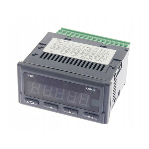
terminals 4 and 5 and replace it by a commercially available portable mA measuring device.
Now the adjustments and settings described above can be carried out. After finishing these
settings the previously disconnected connections are restored.
7.5 Definition of Analog Outputs
Switching the analog output from 4 to 20 mA to 0 to 20 mA occurs by means of a jumper
between the terminals 12 and 13. Should there be a 2nd analog output, it will also be switched
over in the process.

METROTEC
14
Example for 0 to 20 mA and for 4 –20 mA at 0-20% oxygen.
0
5
10
15
20
0 4 8 12 16 20
mA
Oxygen%
0
5
10
15
20
0 5 10 15 20
mA
Oxygen %
Switching the analog output to linear / logarithmic occurs by means of a jumper between the
terminals 16 and 17. Should there be a 2nd analog output, it will also be switched over in the
process.
Example for logarithmic output 0 to 20 mA at 0.01-100% oxygen.

METROTEC
15
Interfaces
7.6 Analog Interfaces
There are 1 or optionally 2 analog 0/4-20 mA interfaces. These can be used at the same time.
7.7 Digital Interfaces
Semiconductor relay for oxygen limit value
Semiconductor relay for readiness
8App for Android Smartphone
The "METROTEC U15 App" for Android Smartphone enables you to look at measuring
values and change configuration settings. First the measuring module must be activated.
This is done by pressing "T2". The top green LED in the right LED array starts to flash. This
signals readiness for establishing a Bluetooth connection. Now the "METROTEC U15 App"
for Android Smartphone can be connected up. As soon as the connection has been
established, the LED will light permanently. Pressing "T2" again will switch the Bluetooth
connection and the green LED off.
An exact description is available in the "METROTEC U15 App" for Android Smartphone
operating instructions.
9Specifications
Measuring range
100 % to 10-35 bar O2
Ambient temperature
0 to 45 degrees Celsius
Measuring accuracy
+/- 0.3 mV of the sensor e.m.f.
+/- 2 degrees Celsius
+/- 2% of the mA output
+/- 2% of the log oxygen partial pressure
Dimensions
ca. 150 x 180 x 90 mm (HxWxD)
Weight
ca. 1.5 kg
Supply voltage
230 VAC, 24 VDC
Observe type plate! Wrong power supply can
destroy the module!
Output
Acc. to sensor type, ca. 100 VA max.
1 (optionally 2) analog output(s)
0/4 –20 mA configurable, floating
2 Relay outputs
configurable for alarms, 1A, 24 V (ohmic)

METROTEC
16
10 Connection Diagrams
Note:
Digital outputs are floating semiconductor contacts (1A, 24V)
mA Output 1 and 2 are electrically isolated from one another.
Connecting sensors
Note: Please refer to the operating instructions of the respective sensor.
Extraktive Sensoren
Pin
Function
1
Heating
2
Heating
3
Sensor +
4
Sensor -
Inline-Sensoren
Pin
Function
1
Thermocouple +
2
Thermocouple -
3
Sensor +
4
Sensor -

METROTEC
17
U15-Digital
Terminal
Function
Definition
1
230 VAC
Supply
2
230 VAC
Supply
3
PE (Protective Earth)
Protective Earth
4
mA+
Measured value output 1 +
5
mA-
Measured value output 1 -
6
----
----
7
----
----
8
Semiconductor relay
Readiness 24 VDC, 1 A
9
Semiconductor relay
Readiness 24 VDC, 1 A
10
Semiconductor relay
Limit value 24 VDC, 1 A
11
Semiconductor relay
Limit value 24 VDC, 1 A
12
Connection to 13
Connection if 0-20 mA
13
Connection to 12
Connection if 0-20 mA
14
----
Test output for factory setting
15
----
Test output for factory setting
16
Connection to 17
Connection if logarithmic measuring output
17
Connection to 16
Connection if logarithmic measuring output
U15-Digital-2
Terminal
Function
Definition
1
230 VAC
Supply
2
230 VAC
Supply
3
PE (Protective Earth)
Protective Earth
4
mA+
Measured value output 1 +
5
mA-
Measured value output 1 -
6
mA+
Measured value output 2 +
7
mA-
Measured value output 2 -
8
Semiconductor relay
Readiness 24 VDC, 1 A
9
Semiconductor relay
Readiness 24 VDC, 1 A
10
Semiconductor relay
Limit value 24 VDC, 1 A
11
Semiconductor relay
Limit value 24 VDC, 1 A
12
Connection to 13
Connection if 0-20 mA
13
Connection to 12
Connection if 0-20 mA
14
----
Test output for factory setting
15
----
Test output for factory setting
16
Connection to 17
Connection if logarithmic measuring output
17
Connection to 16
Connection if logarithmic measuring output

METROTEC
18
U15-Digital-C
Terminal
Function
Definition
1
230 VAC
Supply
2
230 VAC
Supply
3
PE (Protective Earth)
Protective Earth
4
mA+
Measured value output 1 +
5
mA-
Measured value output 1 -
6
----
----
7
----
----
8
Semiconductor relay
Readiness 24 VDC, 1 A
9
Semiconductor relay
Readiness 24 VDC, 1 A
10
Semiconductor relay
Limit value 24 VDC, 1 A
11
Semiconductor relay
Limit value 24 VDC, 1 A
12
Connection to 13
Connection if 0-20 mA
13
Connection to 12
Connection if 0-20 mA
14
----
Test output for factory setting
15
----
Test output for factory setting
16
Connection to 17
Connection if logarithmic measuring output
17
Connection to 16
Connection if logarithmic measuring output
U15-Digital-2C
Terminal
Function
Definition
1
230 VAC
Supply
2
230 VAC
Supply
3
PE (Protective Earth)
Protective Earth
4
mA+
Measured value output 1 +
5
mA-
Measured value output 1 -
6
mA+
Measured value output 2 +
7
mA-
Measured value output 2 -
8
Semiconductor relay
Readiness 24 VDC, 1 A
9
Semiconductor relay
Readiness 24 VDC, 1 A
10
Semiconductor relay
Limit value 24 VDC, 1 A
11
Semiconductor relay
Limit value 24 VDC, 1 A
12
Connection to 13
Connection if 0-20 mA
13
Connection to 12
Connection if 0-20 mA
14
----
Test output for factory setting
15
----
Test output for factory setting
16
Connection to 17
Connection if logarithmic measuring output
17
Connection to 16
Connection if logarithmic measuring output

METROTEC
19
U15-Digital-24
Terminal
Function
Definition
1
24 VDC +
Supply
2
24 VDC -
Supply
3
PE (Protective Earth)
Protective Earth
4
mA+
Measured value output 1 +
5
mA-
Measured value output 1 -
6
----
----
7
----
----
8
Semiconductor relay
Readiness 24 VDC, 1 A
9
Semiconductor relay
Readiness 24 VDC, 1 A
10
Semiconductor relay
Limit value 24 VDC, 1 A
11
Semiconductor relay
Limit value 24 VDC, 1 A
12
Connection to 13
Connection if 0-20 mA
13
Connection to 12
Connection if 0-20 mA
14
----
Test output for factory setting
15
----
Test output for factory setting
16
Connection to 17
Connection if logarithmic measuring output
17
Connection to 16
Connection if logarithmic measuring output
U15-Digital-224
Terminal
Function
Definition
1
24 VDC +
Supply
2
24 VDC -
Supply
3
PE (Protective Earth)
Protective Earth
4
mA+
Measured value output 1 +
5
mA-
Measured value output 1 -
6
mA+
Measured value output 2 +
7
mA-
Measured value output 2 -
8
Semiconductor relay
Readiness 24 VDC, 1 A
9
Semiconductor relay
Readiness 24 VDC, 1 A
10
Semiconductor relay
Limit value 24 VDC, 1 A
11
Semiconductor relay
Limit value 24 VDC, 1 A
12
Connection to 13
Connection if 0-20 mA
13
Connection to 12
Connection if 0-20 mA
14
----
Test output for factory setting
15
----
Test output for factory setting
16
Connection to 17
Connection if logarithmic measuring output
17
Connection to 16
Connection if logarithmic measuring output

METROTEC
20
U15-Digital-C24
Terminal
Function
Definition
1
24 VDC +
Supply
2
24 VDC -
Supply
3
PE (Protective Earth)
Protective Earth
4
mA+
Measured value output 1 +
5
mA-
Measured value output 1 -
6
----
----
7
----
----
8
Semiconductor relay
Readiness 24 VDC, 1 A
9
Semiconductor relay
Readiness 24 VDC, 1 A
10
Semiconductor relay
Limit value 24 VDC, 1 A
11
Semiconductor relay
Limit value 24 VDC, 1 A
12
Connection to 13
Connection if 0-20 mA
13
Connection to 12
Connection if 0-20 mA
14
----
Test output for factory setting
15
----
Test output for factory setting
16
Connection to 17
Connection if logarithmic measuring output
17
Connection to 16
Connection if logarithmic measuring output
U15-Digital-2C24
Terminal
Function
Definition
1
24 VDC +
Supply
2
24 VDC -
Supply
3
PE (Protective Earth)
Protective Earth
4
mA+
Measured value output 1 +
5
mA-
Measured value output 1 -
6
mA+
Measured value output 2 +
7
mA-
Measured value output 2 -
8
Semiconductor relay
Readiness 24 VDC, 1 A
9
Semiconductor relay
Readiness 24 VDC, 1 A
10
Semiconductor relay
Limit value 24 VDC, 1 A
11
Semiconductor relay
Limit value 24 VDC, 1 A
12
Connection to 13
Connection if 0-20 mA
13
Connection to 12
Connection if 0-20 mA
14
----
Test output for factory setting
15
----
Test output for factory setting
16
Connection to 17
Connection if logarithmic measuring output
17
Connection to 16
Connection if logarithmic measuring output
This manual suits for next models
1
Table of contents
Other METROTEC Measuring Instrument manuals
Popular Measuring Instrument manuals by other brands

Agilent Technologies
Agilent Technologies N5502A installation guide

Blue-White industries
Blue-White industries F-451 instruction manual

MIDWESTERN INSTRUMENTS
MIDWESTERN INSTRUMENTS Magnecord PT6-6 Series Instruction

UNITY Lasers
UNITY Lasers RAW 1.7 user manual

Berthold
Berthold BTwave LB 571-02 operating manual

Tektronix
Tektronix TriMode P7700 Series Technical reference