VOH VISIOTEST User manual

V9.0, 06.07.2018
VISIOTEST
USER GUIDE

VOH SA
GU-04-06-01
User guide
VISIOTEST
Version 8.0
Created 12/2017
Page 2 / 27
Table of Contents:
1GENERAL INFORMATION ............................................................................................................................................3
1.1 GUARANTEE....................................................................................................................................................................3
1.2 SECURITY .......................................................................................................................................................................3
1.3 TRANSPORT ....................................................................................................................................................................4
1.4 STORAGE........................................................................................................................................................................4
2PRODUCT DESCRIPTION ..............................................................................................................................................5
3CONTENTS AND ADDITIONAL OPTIONS.......................................................................................................................6
4USER INTERFACE .........................................................................................................................................................7
4.1 HMI PANEL CONNECTORS.................................................................................................................................................7
4.2 FUNCTIONS.....................................................................................................................................................................7
4.3 DEVICE SETTINGS.............................................................................................................................................................8
4.4 START SCREEN .................................................................................................................................................................9
4.4.1 Administrator Mode and SAV access ..........................................................................Erreur ! Signet non défini.
4.5 ADMINISTRATOR MODE ..................................................................................................................................................10
4.5.1 Adding a sensor.................................................................................................................................................12
4.5.2 Add Program .....................................................................................................................................................13
4.5.3 Import / Export sensors (and their programs) ..................................................................................................14
4.5.4 Administrator Mode: Main screen ....................................................................................................................15
4.6 USER MODE .................................................................................................................................................................16
4.6.1 Control Mode / Production Mode .....................................................................................................................18
4.6.2 Statistic module ................................................................................................................................................19
4.6.3 Measurement History Access............................................................................................................................20
4.6.4 Additional Functions and Transfer of DATA ......................................................................................................21
4.7 TRANSFER RESULTS VIA USB CABLE ...................................................................................................................................23
4.8 SERVICE (SAV) MODE ....................................................................................................................................................25
4.8.1 Calibration of FORCETEST sensors ....................................................................................................................25
4.8.2 Torque sensors calibration ................................................................................................................................26
5EXCLUSION OF RESPONSIBILITY AND/OR GUARANTEE .............................................................................................27
6MAINTENANCE AND SERVICE....................................................................................................................................27
7REPRESENTATION/DISTRIBUTION .............................................................................................................................27
Track changes :
Version
Date
Written
Change
Validated
Approved
V8.0
01.12.2017
JSA/BAP
Update V3.01 SW
V9.0
06.07.2018
BAP
Update V4.01 SW (.csv, basic mode,
units)

VOH SA
GU-04-06-01
User guide
VISIOTEST
Version 8.0
Created 12/2017
Page 3 / 27
1 General information
1.1 Guarantee
VOH SA warrants this product against any defects in manufacturing or in materials under normal conditions of
use and service for a duration of two years from the date of commissioning at the client’s premises. If, at any time
during the guarantee period, the product is found to be defective or fails, VOH SA shall repair or replace it (at the
discretion of VOH SA).
If the product is defective, please call VOH Customer Service on +41(32) 945 17 45.
The warranty shall not apply if VOH SA proves the default or failure is due to improper use of the equipment.
The product is equipped with seals of warranty. Breaking or severing these seals leads to cancellation of the
warranty.
Figure 1: Seal of warranty
The scope of VOH SA’s liability is limited to the repair or the replacement of the product under the terms set out
above.
VOH SA SHALL NOT BE HELD LIABLE FOR ANY LOSS OR DAMAGES, INCLUDING INCIDENTAL OR
CONSEQUENTIAL DAMAGES ARISING DIRECTLY OR INDIRECTLY FROM A BREACH OF THE
GUARANTEE, EXPRESS OR IMPLIED, OR ANY OTHER FAILURE OF THIS PRODUCT. THIS GUARANTEE
IS THE ONLY EXPRESS GUARANTEE PROVIDED BY VOH SA FOR THIS PRODUCT.
This guarantee only covers the initial buyer and is not transferable.
If you have any questions regarding the guarantee, please write to VOH SA at the following address:
VOH SA
La Praye 5a
CH-2608 Courtelary
Telephone: +41(32) 945 17 45
Fax: +41(32) 945 17 55
Internet: http://www.voh.ch
1.2 Security
Notice
Do not use the VISIOTEST if it has been damaged. Prior to starting up the machine, first inspect its
control box and electrical connections.
The VISIOTEST must be used in accordance with the specified guidelines of the fabricator (VOH SA).
Only personnel who have been properly formed in the user procedure, and have read this document
should use the VISIOTEST.

VOH SA
GU-04-06-01
User guide
VISIOTEST
Version 8.0
Created 12/2017
Page 4 / 27
Warning!!!
Please carefully read the information contained in this manual before using the device. Improper use
could severely damage the system or peripheral devices.
The VISIOTEST must be used in an industrial environment.
Before connecting the device for the first time, verify that the voltage corresponds to the suggested
voltage for the device (see the attached label)
In the instance that the machine is not used for a prolonged period of time, disconnect the power cable.
Do not under any circumstances take apart the VISIOTEST machine. Only the manufacture, VOH SA, is
entitled to repair or replace defective components.
This product should only be stored and employed at a room temperature not falling below 10°C or
exceeding 40°C (50-104 °F).
This User Guide must be kept in close proximity to the machine.
Please use only electric cables that correspond to the requirements of the VISIOTEST.
DO not place the VISIOTEST in close proximity to a heat source.
1.3 Transport
It is suggested that when transported over long or short distances that shock-preventative packaging (provided
upon delivery of the machine) is used.
1.4 Storage
The VISIOTEST must be stored in a dry place, protected from humidity and dust. The storage temperature
should not fall below 10°C (50° F), or surpass 40°C (104 °F).

VOH SA
GU-04-06-01
User guide
VISIOTEST
Version 8.0
Created 12/2017
Page 5 / 27
2 Product description
The VISIOTEST is a display unit for torque and force sensors. It is compatible with Atlas-Copco Microtorque,
Torquetest VOH and Forcetest VOH sensors (See Figure 2).
Technical specifications
Dimensions and weight
180mm x 100mm x
135mm (w x d x h) / 0.5
kg
Weight with power supply and cable
2kg

VOH SA
GU-04-06-01
User guide
VISIOTEST
Version 8.0
Created 12/2017
Page 6 / 27
3 Contents and additional options
Description
VISIOTEST and universal stylus pen for touch screen
Power supply 24V(input 110-240VAC, 50-60 Hz)
Power supply cord for CEE devices
User Guide
Figure 2: VISIOTEST and peripheral devices

VOH SA
GU-04-06-01
User guide
VISIOTEST
Version 8.0
Created 12/2017
Page 7 / 27
4 User Interface
4.1 HMI Panel Connectors
Figure 3: HMI VISIOTEST connectors
4.2 Functions
The VISIOTEST functions using a four-tier system of access:
- Basic: open access, no programming required
- User : open access, programming required
- Programming mode (admin) : password protected access
- SAV : password protected access
The diagram below depicts the basic functions of the device. Each function is presented in greater detail in the
paragraphs that follow.
Figure 4: Diagram of general functions of the VISIOTEST
Access to Programming (admin) Mode and SAV Mode is password protected. It is in Programming Mode that it is
possible to add, modify, or delete sensors and/or programs. These functions are presented in the following
paragraphs.

VOH SA
GU-04-06-01
User guide
VISIOTEST
Version 8.0
Created 12/2017
Page 8 / 27
4.3 Device Settings
To access device settings, it is necessary to click on the settings icon while the device is starting up (démarrage).
Figure 5: Screen during start up (Settings icon at top left)
From the Settings screen, users can modify language, date and time, select a printer, and change the password
for Administrator Mode.
Figure 6: VISIOTEST Settings
This configuration screen is for choosing after how much time of inactivity the brightness of the screen will be
reduced and at which intensity. Any click on the screen will set it back to full brightness.
Figure 7: Screensaver configuration

VOH SA
GU-04-06-01
User guide
VISIOTEST
Version 8.0
Created 12/2017
Page 9 / 27
4.4 Start screen
4.4.1Sensor list or basic measure access
Once the VISIOTEST has completed starting up, the home screen will appear. When a torque sensor (button
with “Nm” unit) and a force sensor (button with “N”) are connected, the screen in figure 8 is displayed.
Figure 8: Welcome screen (Information icon at top left)
The button on the right gives access to the list of connected sensor and their programs. The two other buttons
allows access to the “basic” measurement mode for each type of sensor connected.
If no or only 1 sensor is connected, the screens are presented according to the possibilities below:
Figure 9: Welcome screen (variation according to the connected sensors)
To access the info page or SAV, first select the Information icon. A selection of information relative to the
different functions of the device will appear on the screen. Select the SAV icon to access the Password login
screen.
Default password for SAV Mode: 1397
Figure 10: Administrator Mode/ SAV access

VOH SA
GU-04-06-01
User guide
VISIOTEST
Version 8.0
Created 12/2017
Page 10 / 27
4.5 Mode “Basic measurement”
This mode allows direct and simple measurement via one of the connected sensors.
Figure 11: Mode basic : on the left, a sensor with positive FSR, on the right with a +/- FSR
Symbols and buttons description :
Instantaneous value display
Display of the maximum measured value and possibly minimum value
in the case of a sensor in +/-
Send measurement data button (RS-232, USB and SD save)
Resetting the measurement

VOH SA
GU-04-06-01
User guide
VISIOTEST
Version 8.0
Created 12/2017
Page 11 / 27
4.6 Programming Mode
In Programming Mode, all sensors in the device memory can be viewed, browsed, deleted, and their names can
be modified. To access the programming mode, go to the "Sensors connected" page, click on the edit button
, and enter the admin password (1234) :
Figure 12: Programming Mode access
Each sensor is accompanied by a series of associated programs. An example of typical menu in Administrator
Mode is presented below:
Figure 13: Navigation in Programming Mode
All functions for management of the VISIOTEST are located on the column on the left-hand side of the screen.
1) Create/add a new program if a specific file is selected To create/add when a sensor is selected
highlighted in gray
2) Edit the name of a program, or a selected sensor
3) Delete a sensor or a program
4) Export sensor(s)
5) Import sensor(s)
User edit :
It is possible to authorize (or not) the modification of programs by the user. The « User edit » button located on
the top right of the screen allow this choice. If the button is activated (red), the user can change the tolerances
used. In any case, the user has the possibility to activate or not the “auto-tolerance” (automatic change of the
tolerance in production mode) as well as the “auto-reset” in control mode (automatic reset after measurement
OK).
BIP KO min :
The « BIP KO » button, located on top of the screen, allow the activation of a sound during a « KO min » : in case
the measurement has not reached the MIN tolerance and returns to 0 (Orange KO displayed). Of course, the
“KO” beep has to be activated in the program (see. : § 4.6.4 Administrator Mode: Main screen, page 15).
This parameter is common to all programs.

VOH SA
GU-04-06-01
User guide
VISIOTEST
Version 8.0
Created 12/2017
Page 12 / 27
Simply click on the corresponding line to select a sensor. The selected column (sensor/program) will change
color. The menu can be navigated from top to bottom with the arrow scroll on the right side of the screen.
To alternate between force and torque sensors, the user must click on the column header labeled: « Sensors ».
Figure 14: Alternate between Force <-> Torque
Once a sensor has been selected, the programs associated to that sensor will appear in the « Programs »
column.
When a sensor or a program are selected, it is possible to edit its name or delete it. Please see the below
diagrams for more details:
Figure 15: Edit sensor/program name or delete sensor/program
4.6.1Adding a sensor
Two scenarios are possible when a new sensor is connected to the VISIOTEST:
1) A similar type of sensor already exists in the VISIOTEST memory
2) The sensor is new, and not yet programmed in the VISIOTEST
Figure 16: Creating a new sensor
In the first case, it is possible to associate the new sensor to an existing program. This will create a new sensor
folder, which the user can name. If this option is chosen, the list of sensors available will appear and the
compatible sensors will be appear in black.

VOH SA
GU-04-06-01
User guide
VISIOTEST
Version 8.0
Created 12/2017
Page 13 / 27
Figure 17: Select a sensor to duplicate
Once the sensor has been selected, it is necessary to modify the sensor name to create a new folder. This new
sensor folder will be an exact duplicate of the existing sensor folder, with all the associated programs.
In the instance that the connected sensor is not recognized by the VISIOTEST and no similar sensors are in the
memory, the following screen will appear. It will automatically present the basic information for the newly
connected sensor.
Figure 18: Creating and editing a new sensor
To rename the sensor, select the field « Name ». Once the new name has been entered and confirmed, a new
sensor folder will be created.
4.6.2Add Program
Once a sensor folder has been created, new programs can be added by simply selecting the sensor name and
touching the « + » icon.
Figure 19: Add a program after selecting a sensor

VOH SA
GU-04-06-01
User guide
VISIOTEST
Version 8.0
Created 12/2017
Page 14 / 27
4.6.3Import / Export sensors (and their programs)
In Administrator Mode, it is possible to copy programs from one VISIOTEST and transfer them to another using
an SD card. Once the export icon is selected, the following screen appears.
Figure 20: Export sensors
Once the sensors to export are selected (force sensors or torque sensors), the Administrator can press on the
export icon to copy the sensors to an SD card. When the sensors have all successfully been copied to the SD
card, it is possible to transfer them onto another VISIOTEST. To transfer the data, insert the SD card into the
new VISIOTEST et select « Import » in Administrator Mode. To complete the import, next select the sensor files
to copy and push « Import » a second time.
Figure 21: Import sensors
.

VOH SA
GU-04-06-01
User guide
VISIOTEST
Version 8.0
Created 12/2017
Page 15 / 27
4.6.4Administrator Mode: Main screen
The main screen of Administrator Mode permits the user to modify or edit programs.
To access the main screen in Administrator Mode, it is necessary to:
1) Select a sensor
2) Select a program
3) Double click the selected program
The main screen in Administrator Mode will appear as follows:
Figure 22: Main screen, Administrator Mode
From the main screen tests can be edited (it is not possible to make measurements in this mode). It is also
possible for the Administrator to modify the tolerance of each individual tab with the « Active » icon. The inactive
tabs will not be accessible in normal User mode.
This option allows the Administrator to define the number of stages of each program (for example : a program is
meant to fit 3 hands 3 active tabs versus a program meant to fit one stoneone active tab)
To edit tolerance, press the « Edit » icon. The minimum/maximum effort can be adjusted individually for each
tolerance.
Figure 23: Edit tolerance
The icons on the left permit the following (top to bottom):
Back to the Main Menu
Edit the selected tolerance (right tab)
Access statistics module
Select Production/Control Mode
Acoustic signal
Function footswitch

VOH SA
GU-04-06-01
User guide
VISIOTEST
Version 8.0
Created 12/2017
Page 16 / 27
4.6.5Choice of tolerance units
From the tolerance page, it is possible to choose the units as well as the number of digits of the tolerance by
clicking on the button « » above.
Figure 24: Choice of tolerance units and digits
4.7 User Mode
In User Mode, only the sensors saved in the memory or physically connected to the VISIOTEST are accessible.
Figure 25: User Mode Menu
Once a sensor has been selected, the corresponding programs will be displayed on the screen. To begin a test,
simply select it and press the OK icon to bring up the measurement screen.
Figure 26: To select a sensor or a program

VOH SA
GU-04-06-01
User guide
VISIOTEST
Version 8.0
Created 12/2017
Page 17 / 27
Figure 27: Measurement screen
During the measurement stage, the greatest value measured will appear in the upper frame while the
instantaneous value will appear in the lower frame. A bar-graph permits the user to illustrate the evolution of
effort versus the range sensor used.
Figure 28: Measurement screens
The icons on the left permit the following (top to bottom):
Back to the Main Menu
Edit the selected tolerance (right tab)
Access statistics module
Select Production/Control Mode
Acoustic signal
Function footswitch

VOH SA
GU-04-06-01
User guide
VISIOTEST
Version 8.0
Created 12/2017
Page 18 / 27
4.7.1Control Mode / Production Mode
The VISIOTEST has two modes: Control Mode and Production Mode. It is always possible to change modes
when working in User Mode, independent of the activation of « User Edit ».
Figure 29: Control Mode (AR deactivated/ AR activated)
In Control Mode, it is possible to activate or deactivate Auto-Reset (AR). If Auto-Reset is activated, a reset to
zero will take place immediately three seconds after any completed tolerance measurements (OK). When Auto-
Reset is activated, the data will be automatically transferred following each completed measurement (OK). If this
option is not activated, the user can manually stop the test. This can be done by pushing on the « Reset » icon
on the display screen or on the button behind the FORCETEST sensors. Automatic modifications to the tolerance
are not available in Control Mode.
It is also possible in Control Mode to assign a particular function to the pedal. The options are the following:
Transfer data (via USB and RS-232)
Change tolerance (123451…)
Reset (exit measurement)
Figure 30: Production Mode (AT deactivated/ AT activated)
In Production Mode, it is possible to activate or deactivate Auto-Tolerance (AT). By activating Auto-Tolerance,
the machine will automatically change the tolerance following each completed measurement (OK). If this option is
not activated, the tolerance can be changed manually. This operation can be completed by selecting on the
tolerance tabs (at the right of the display screen), or on the button behind the FORCETEST.
In Production Mode, the receipt of the measurement will be prepared 3 seconds after the completion of a
successful test (OK). The measured value will be automatically transferred to the printer via the USB cable. The
pedal permits the user to reset via Auto-Reset. The Auto-Reset button must be pressed to print the receipt of a
KO measurement.

VOH SA
GU-04-06-01
User guide
VISIOTEST
Version 8.0
Created 12/2017
Page 19 / 27
4.7.2Statistic module
When a measure is completed, the meter (located on the top left of the screen) is incremented. It is then possible
to cancel the last measurement (and those preceding) by using the « Refresh» button located on the top right of
the screen.
Figure 31: Measurement screen with « Refresh » button
Once the measurements are completed, the statistics module can be accessed with a simple touch of the
Statistics icon.
Figure 32: Statistics Module
A measurement is labeled OK if the maximum effort measured is included within the specified tolerance. If the
effort exceeds the tolerance, the measurement is considered KO. In the case that a measurement is below the
tolerance, it is possible to restart the operation and the instantaneous value will be displayed again.
Each tab (tolerance) of each program has its own statistics module. The information relative to the sensor, to the
program, and to the tolerance used are summarized at the top of the screen. The statistics presented are the
following:
Count / %KO
Number of operations completed
% operations outside of the tolerance
Min / Max
Min. effort measured
Max effort measured
Average value of operations
Ecart type :
Process capability
Capability index
Statistics can be reset to zero by pushing on the Reset button on the Statistics Module page. To send the data
vis USB and RS-232 is possible by pressing the DATA button. (cf. :4.8
Warning !
Any and all ongoing statistics will be deleted if the User exits an ongoing test to return to the Main Menu.

VOH SA
GU-04-06-01
User guide
VISIOTEST
Version 8.0
Created 12/2017
Page 20 / 27
4.7.3Measurement History Access
The VISIOTEST permits the User to consult prior measurements completed in a tolerance test (note : if a User
quits an ongoing test, the data will be lost).
Access the measurement history using the cursors on the left side of the meter. In order to navigate, the sensor
must first be in a resting position (following a Reset maximum value and instantaneous values are shown in
black.
Figure 33: Resting state following a RESET/AUTO-RESET
Prior values may also be reviewed. The maximum value and measurement status will be shown.
Figure 34: Displaying a value from the History
When displaying values from the History, the RESET button will blink. Pressing the RESET button will permit the
User (cf.: Figure 33) to return to the ongoing measurement. When a historical value is displayed, pressing the
DATA button will transfer the measurement data via USB and saved onto the SD card.
Table of contents
Popular Measuring Instrument manuals by other brands
Prostat
Prostat PFM-711A user manual
VPInstruments
VPInstruments VPFlowScope M probe user manual
Blackline Safety
Blackline Safety G7 EXO Technical user's manual
MPFiltri
MPFiltri LPA2 user guide
Kyoritsu Electrical Instruments Works, Ltd.
Kyoritsu Electrical Instruments Works, Ltd. 5000 instruction manual
Kyoritsu Electrical Instruments Works, Ltd.
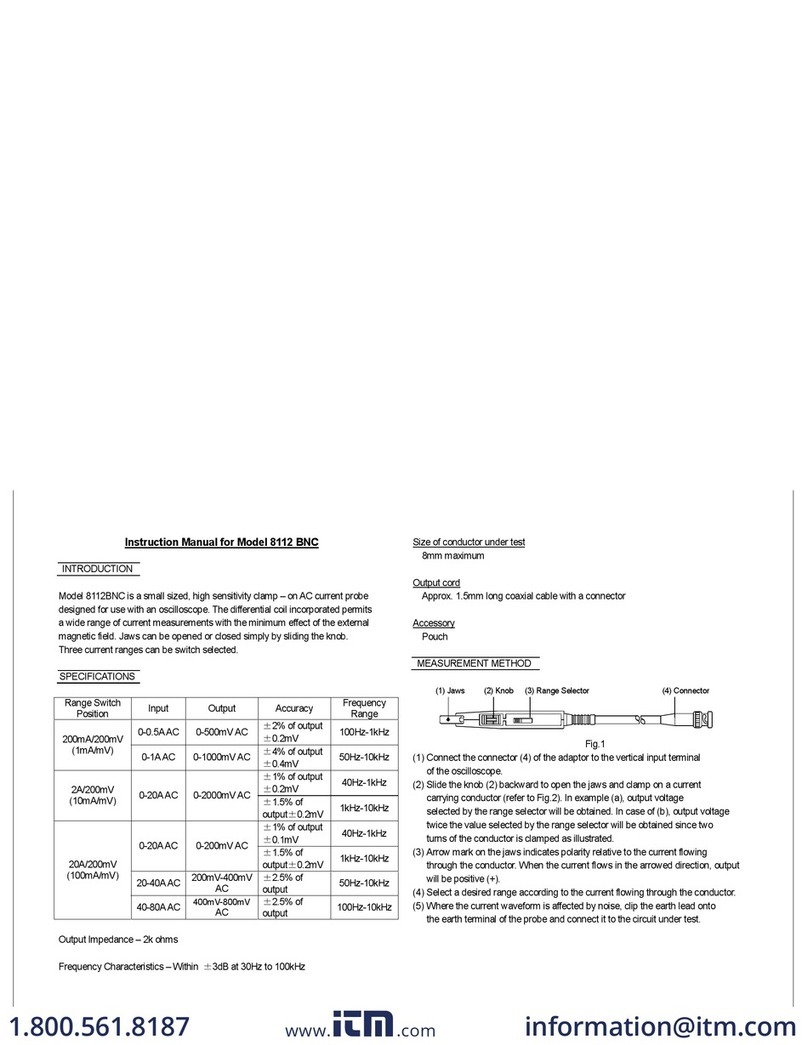
Kyoritsu Electrical Instruments Works, Ltd. 8112 BNC instruction manual
