Meyra 1.163 User manual

GB SERVICE MANUAL
SCOOTER
Models: 1.163
3.264
1.363 / 1.364
2.363 / 2.364
2.663 / 2.664
2.563 / 2.564
1
We move people.

2

3
Contents
Foreword .........................................................................................................................6
Requirements ..........................................................................................................................6
Term definitions ......................................................................................................................7
Vehicle identification .....................................................................................................7
Electronic vehicles ...................................................................................................................7
Overview .........................................................................................................................8
Cityliner 306, model 1.163 .....................................................................................................8
Cityliner 408+, model 3.264 ...................................................................................................8
Cityliner 406+, model 3.264 ...................................................................................................8
Cityliner 310+, model 1.363 ...................................................................................................9
Cityliner 410+, model 1.364 ...................................................................................................9
Cityliner 312, model 2.363 ...................................................................................................10
Cityliner 412, model 2.364 ...................................................................................................10
Cityliner 315, model 2.663 ...................................................................................................11
Cityliner 415, model 2.664 ...................................................................................................11
Ortocar 315 SP II, model 2.563 .............................................................................................12
Ortocar 415 SP II, model 2.564 .............................................................................................12
Drive ..............................................................................................................................13
Replacing the drive - Cityliner .............................................................................................13
Separating electric connections ...................................................................................14
Disassembly of the drive ...............................................................................................16
Assembly of the drive unit ............................................................................................19
Replacing the drive - Ortocar SP II ......................................................................................21
Disassembly of the drive ...............................................................................................22
Assembly of the drive ....................................................................................................24
Subsequent operations ........................................................................................................26
Functional checks ...........................................................................................................26
Brakes ............................................................................................................................27
Motor brake ..........................................................................................................................27
Magnetic brake .....................................................................................................................27
Disassembly of the spring pressure brake (magnetic brake) .....................................28
Carbon brushes ..............................................................................................................30
Alignment .....................................................................................................................33
Checking the alignment .......................................................................................................33
Adjusting the straight forward course (parallelity of front to rear wheels) ...................34
Adjusting the alignment ......................................................................................................34
Revetment .....................................................................................................................35
Removing the steering column revetment .........................................................................35
Attaching the steering column revetment .........................................................................37

4
Parking brake ................................................................................................................38
Renewing the bowden cable of the drum brake ..............................................................38
Disassembly of the bowden cable: ...............................................................................38
Pre-assembly of the bowden cable: .............................................................................38
Steering column locking device ...................................................................................40
Lighting .........................................................................................................................42
Adjusting the headlights .....................................................................................................42
Description of the rear lighting ...........................................................................................42
Electronic components ................................................................................................43
Control panel ........................................................................................................................43
Exchangeable electronic parts .............................................................................................44
Operating keypad PCB .........................................................................................................45
Voltage transformer .............................................................................................................48
Director ..................................................................................................................................49
Exchanging the director driving lever complete ........................................................49
Exchanging the director foot pedal complete ............................................................50
Exchanging the director hand gas complete ..............................................................51
Power electronic ...........................................................................................................52
Parametrics ............................................................................................................................53
Programming sequence .......................................................................................................54
Programming unit SP1 .................................................................................................55
Purpose ..................................................................................................................................55
Overview ...............................................................................................................................55
Driving parameter ................................................................................................................56
Programming sequence .......................................................................................................57
Standard settings ..................................................................................................................59
Tips for settings .....................................................................................................................59
PC-Programming ...........................................................................................................60
Purpose ..................................................................................................................................60
Programming sequence .......................................................................................................60
Operating panel with LCD display ..............................................................................61
Service-menu .........................................................................................................................61
Selecting the service menu ...........................................................................................61
Menu navigation ...........................................................................................................61
Clock adjust ...........................................................................................................................63
Scooter type (model) ............................................................................................................64
Wheel diameter ....................................................................................................................65
Audible warning ...................................................................................................................65
Tiller menu ............................................................................................................................66
Speed adjust ..........................................................................................................................67
Backlight menu .....................................................................................................................69
Hours (operating hours) .......................................................................................................69

5
Drive batteries ..............................................................................................................70
Battery replacement on model 1.163 .................................................................................70
Battery replacement on other models ................................................................................70
Maintenance .................................................................................................................71
Maintenance checklist ..........................................................................................................72
Electrical system .............................................................................................................72
Mechanic ........................................................................................................................74
DIN norms and guidelines .............................................................................................75
Error code display ........................................................................................................76
Notes ..............................................................................................................................78

6
FOREWORD
This service manual is designated for the author-
ised dealer.
☞ It is completed by the following documenta-
tion:
– the model dependent operating manual
(a users manual is supplied with each vehicle),
– the model dependent operating manual < LCD-
Display >,
(a users manual is supplied with each vehicle),
– the safety and general handling instructions <
Electronic vehicles >.
– the model dependent spare parts list.
The required spare parts lists will be sent to you
upon demand.
All documents can also be downloaded from the
following site in the internet:
< www.meyra-ortopedia.de >.
Requirements
Special knowledge is required to carry out the
maintenance work described in this service manual
and may therefore only be carried out by educated
qualified personnel.
☞ We therefore offer vehicle specific courses that
provide the specialised personnel with the re-
quired qualification.
!
Attention:
Watch for danger of jamming during all respec-
tive work!
☞ Note:
Tighten all screwed connections, when not spe-
cially declared, according to table torque accord-
ing to DIN for screwed connections, view chap-
ter < Maintenance/Maintenance checklist/DIN
norms and guidelines >.
MEYRA-ORTOPEDIA Vertriebsgesellschaft mbH
Meyra-Ring 2 · D-32689 Kalletal-Kalldorf
K 9232200005308 2009-52
5857098
100
kg
350
kg
max. 15 km/h
18 %
18 %
Type 2.663
210 140
KG
Electronic vehicles
7
VEHICLE IDENTIFICATION
For a definite vehicle identification in case you have
questions, or for spare parts orders, the following
data can be read off of the type plate:
1. The model description (in the field Type resp.
Typ)
2. The serial number (beside the space SN)
☞ On older vehicles it is the vehicle-identification-
number (underneath the space Fz-I-Nr)
Term definitions
Here you will find explanations to the term used in
this manual:
Service position (1)
– Scooter without seat and with lifted battery cov-
er in order to conduct maintenance work unen-
cumbered.
☞ Access to the electronic modules requires a pre-
vious removal of the rear revetment.
Working on the vehicle
☞ For maintenance and repairs the vehicle is to be
switched off and secured against unintention-
ally rolling away. Additionally the plugged con-
nections of the battery cables are to be pulled.
8
OVERVIEW
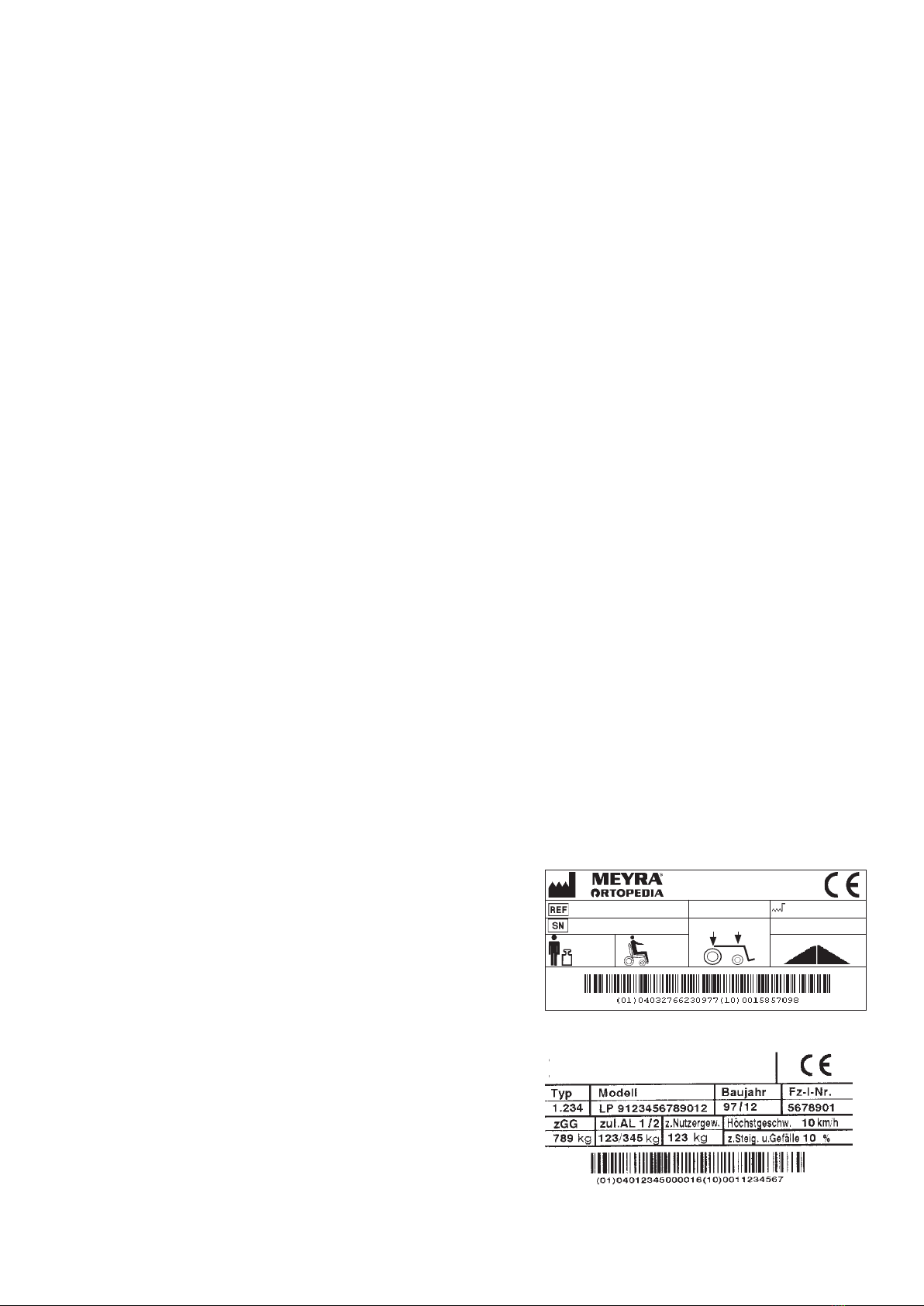
Cityliner 306, model 1.163
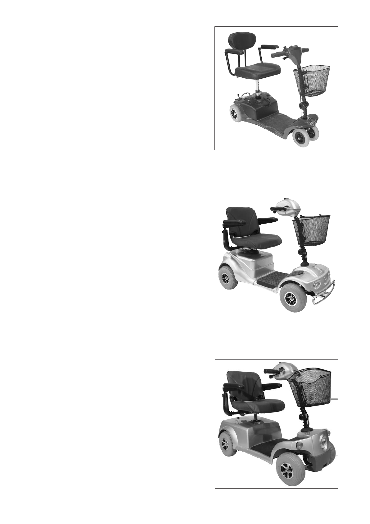
Cityliner 408+, model 3.264
Cityliner 406+, model 3.264

9
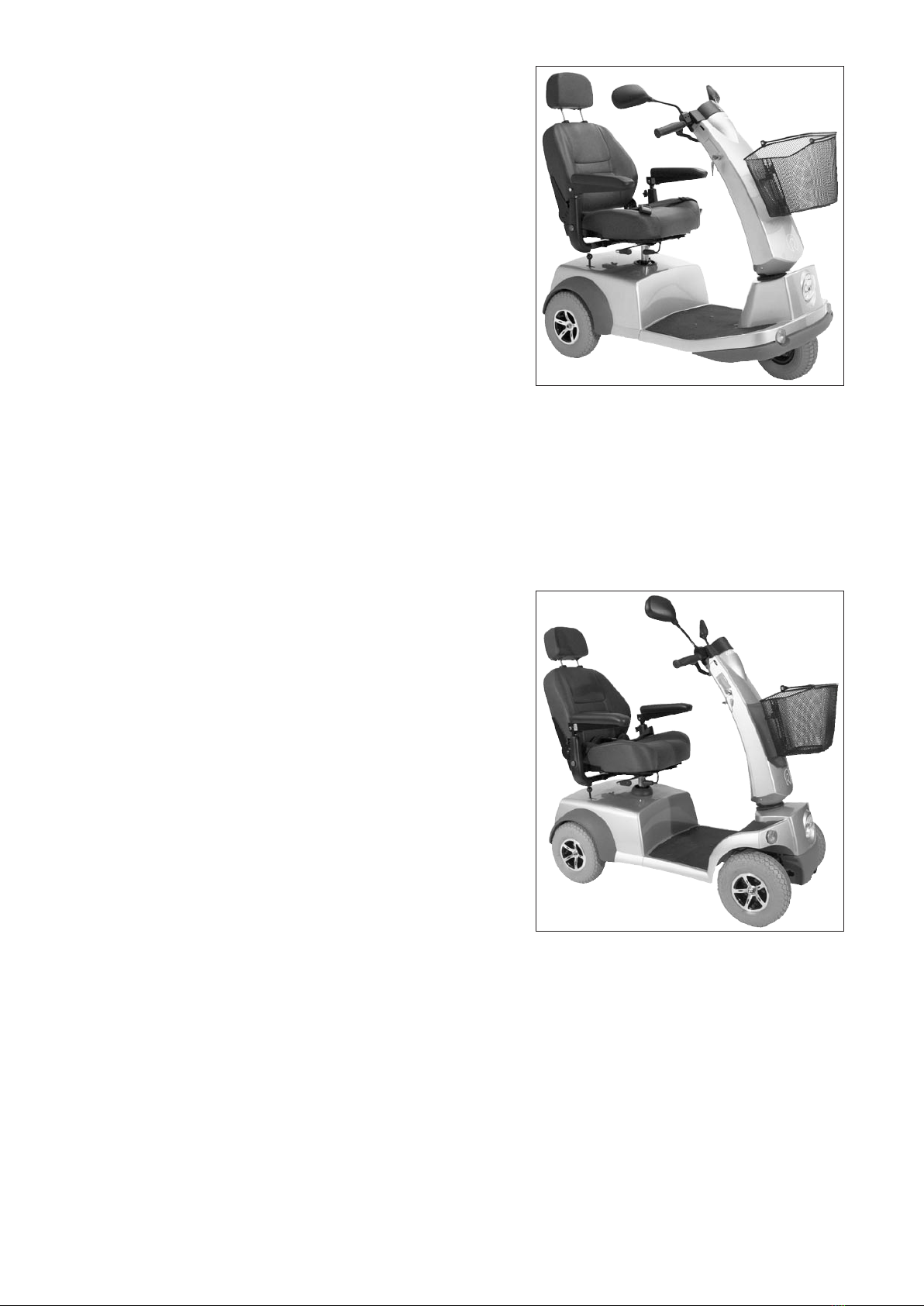
Cityliner 310+, model 1.363
Cityliner 410+, model 1.364
10
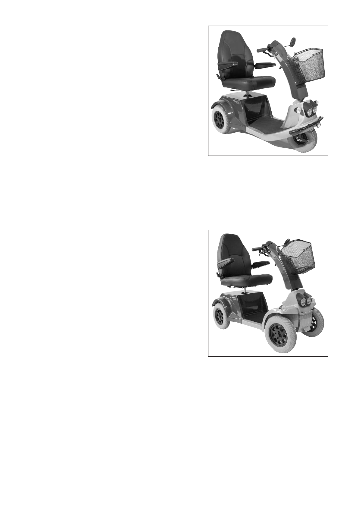
Cityliner 312, model 2.363
Cityliner 412, model 2.364

11
Cityliner 315, model 2.663
Cityliner 415, model 2.664
12
Ortocar 315 SP II, model 2.563
Ortocar 415 SP II, model 2.564
1
5
5
6
5
4
2
3
5
6
13
DRIVE
The power drive is fitted with a permanent mag-
net-Motor for 24 Volt DC current.
The drive [1] consists of:
– the motor (2),
– Carbon brushes (5),
– the magnetic brake (3),
– Drive locking switch (6),
– the differential gear (4).
☞ Note:
If the motor buckles while driving or does not
bring any performance without an error being
indicated, the carbon brushes and the collector
in the motor (2) have to be checked.
☞ Worn carbon brushes with dull contacts are to
be replaced.
☞ Therefore observe chapter < Carbon brushes >.
Replacing the drive - Cityliner
Preparations
1. To replace the drive the rear chassis has to be
detached [5].
☞ Therefore observe the corresponding chapter of
the respective < user manual >.
2. Afterwards disassemble the drive wheels [6].
1
3
1
1
2
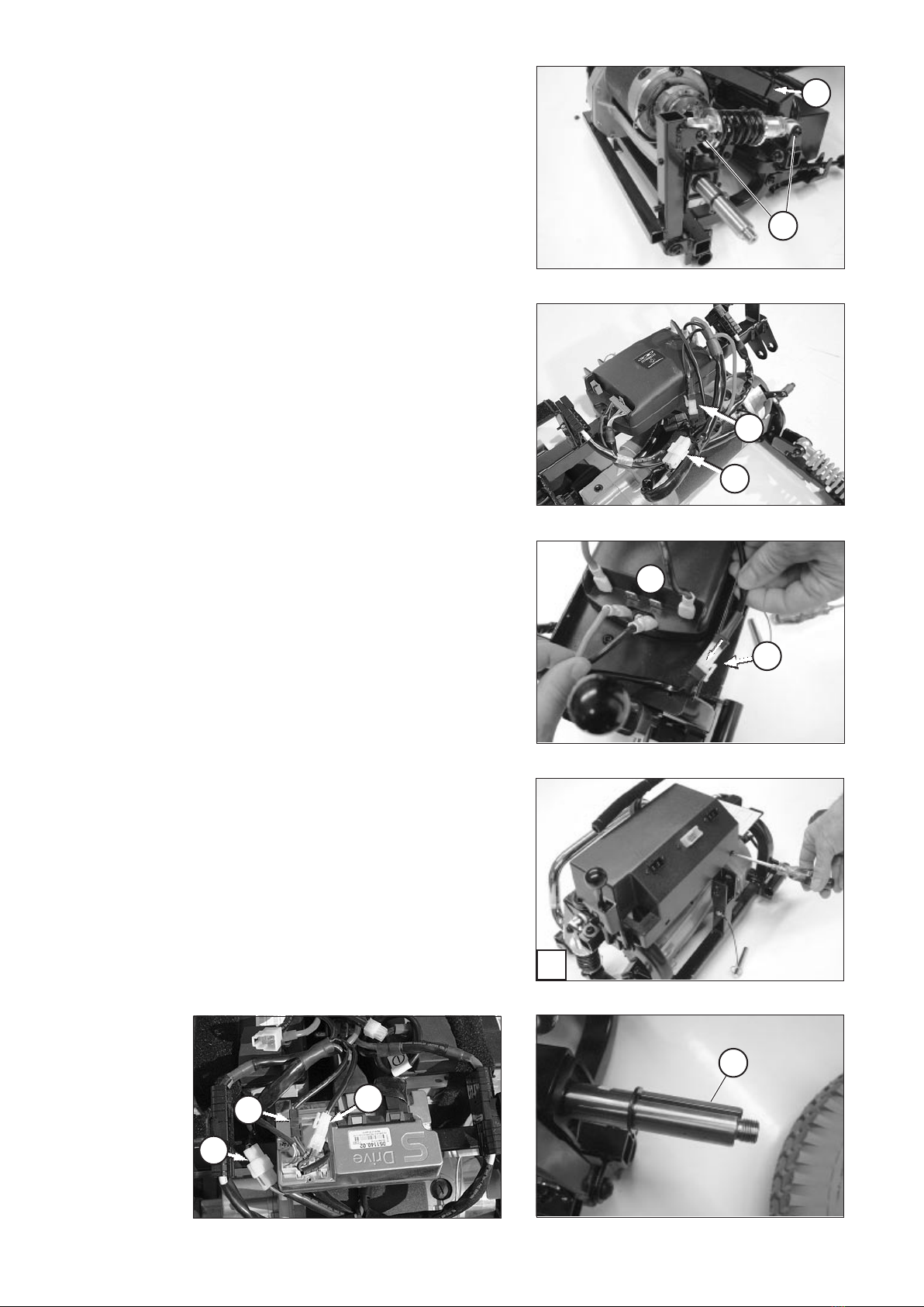
14
Separating electric connections
1. If necessary remove the electronic cover [1].
2. Unplug the cable connections of the motor and
spring pressure brake (if required drive locking
lever, only in respect to the S-Drive electronic)
from the control electronic [2].
3. Remove the cable binders (3).
2
1
1
3
4
15
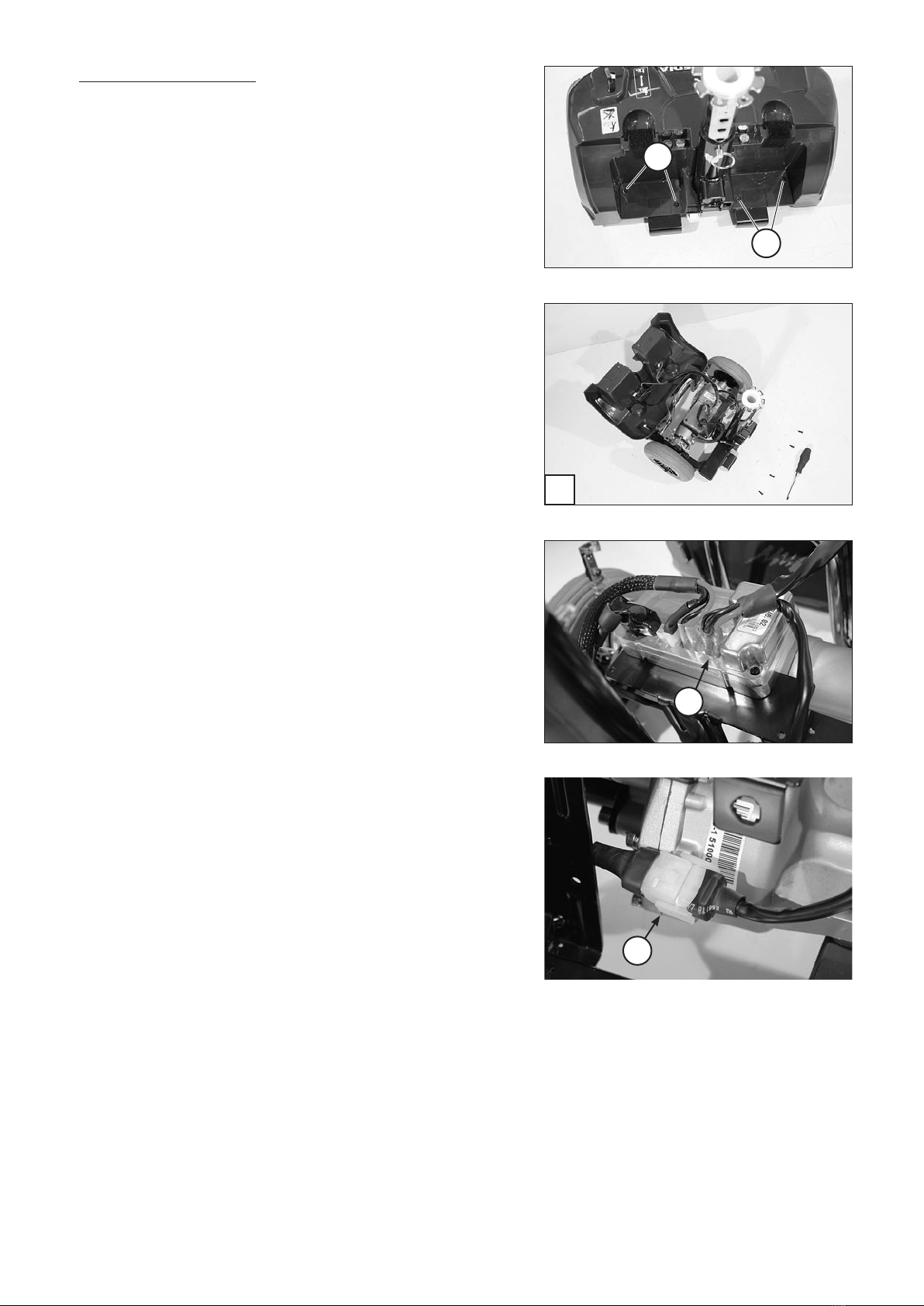
Only on model 1.163
1. Unscrew the countersunk screws (1) and care-
fully lift of the rear cover [2].
2. Pull the cable shoes (3) of the battery cable.
3. Disconnect the plugged connection (4) of the
motor cable.
☞ For this activate the release lever of the locking
device.
1
1
23
4
3
16
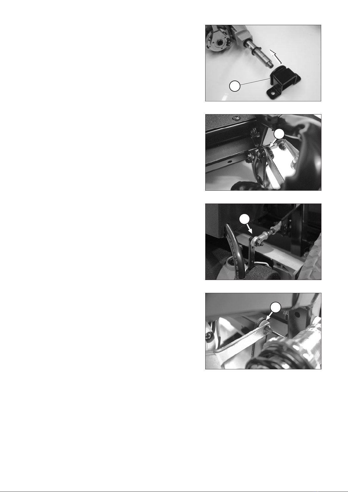
Disassembly of the drive
☞ Note:
Before removal of the drive you should observe
the position of the motor for the subsequent as-
sembly.
Model 1.163,
Model 3.264,
Model 1.363 / 1.364 and
Model 2.363 / 2.364:
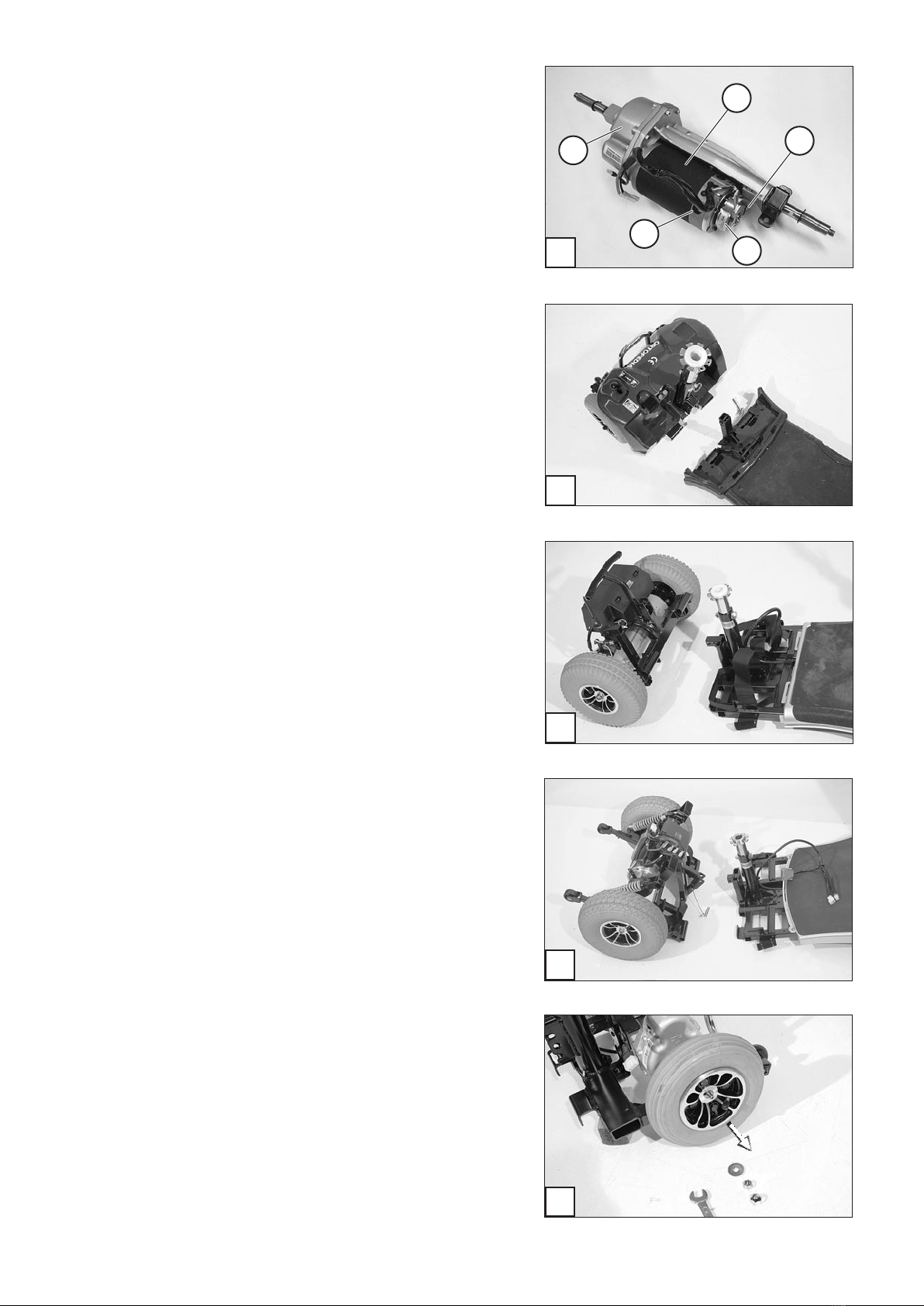
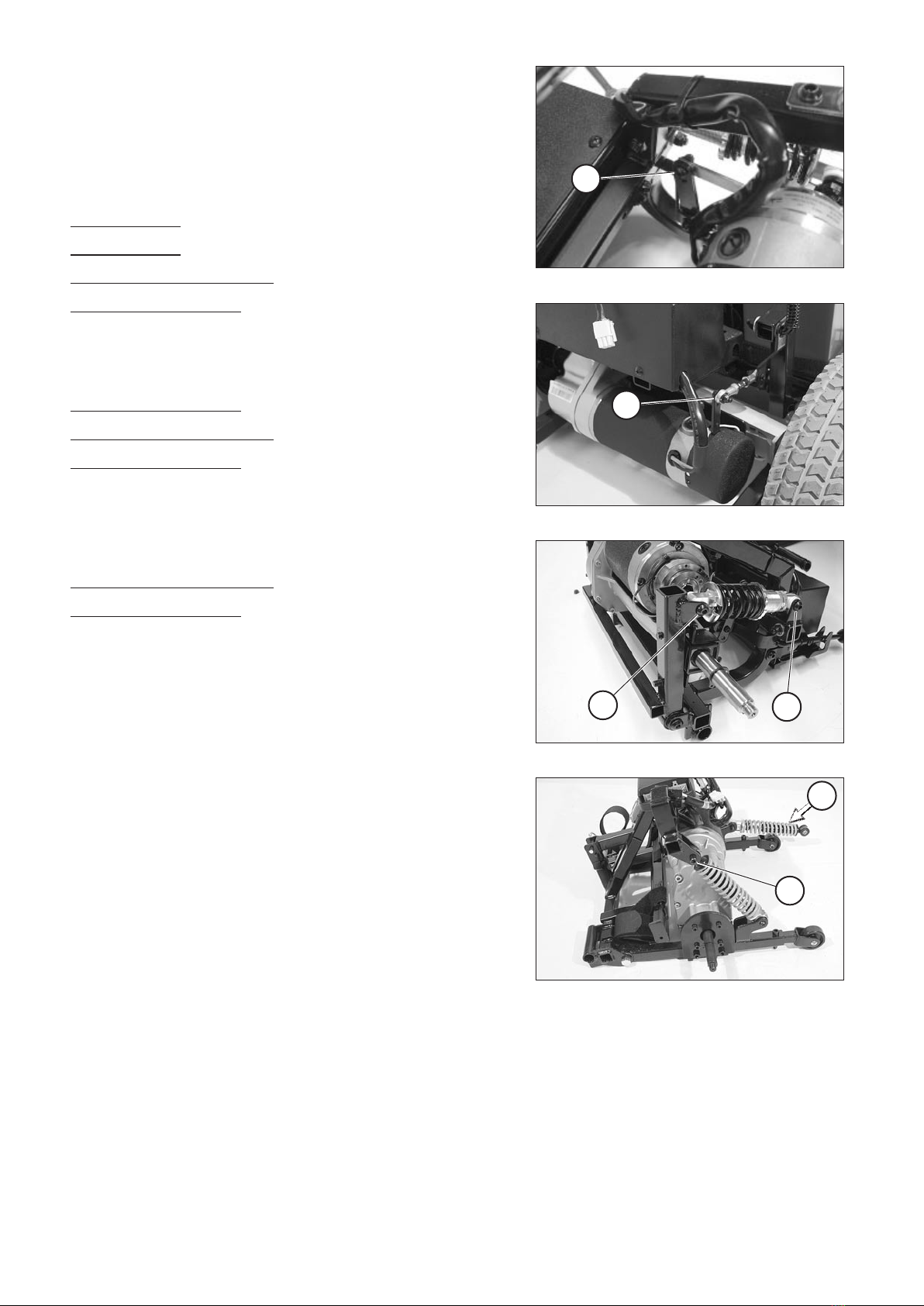
1. Disconnect the joint connection (1) of the hand
ventilated pressure brake (magnetic brake).
Model 1.363 / 1.364,
Model 2.363 / 2.364 and
Model 2.663 / 2.664:
2. Dismantle the two screwed connections (2)+(3)
and remove the shock absorber.
or
Model 1.363 / 1.364 and
Model 2.663 / 2.664:
2. Dismantle the upper screwed connections (3)
and swivel the shock absorber down toward the
back (4).

7
7
6
6
5
17
Model 3.264,
Model 1.363 / 1.364 and,
Model 2.363 / 2.364:
3. Dismantle the two screwed connections (5) of
the attachment clamp on both sides of the drive
[6].
4. Lift the drive out of the frame [7].

8
66
55
8
77
18
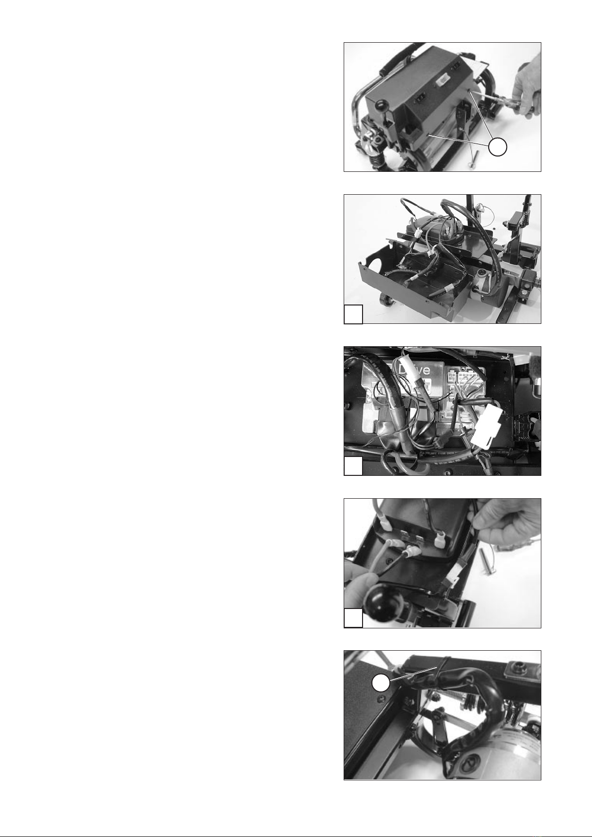
5. Pull off the attachment clamp with damping
rubber on both sides of the drive [8].
Only on model 1.163
3 Disassemble the screwed connections (6) to re-
move the ram guard.
4. Dismantle the two screwed connections (5) of the
attachment clamp on both sides of the drive.
5. Lift the drive out of the frame.
Only on model 2.663 / 2.664:
4. Dismantle the two screwed connections (7) of
the attachment plate on both sides of the drive.
5. Dismantle the four flange screws (8) on both
sides of the drive and remove the attachment
plates.
6. Lift the drive out of the frame.
1
2
2
3
19
Assembly of the drive unit
Assembly of the drive is achieved in reverse order
to the disassembly.
1. Slide the attachment clamp with the damping
rubber (1) onto the square of the drive.
2. Insert the drive into the rear frame and align it.
– The magnetic brake is located in driving direc-
tion to the right.
☞ Note:
Watch for the correct assembly position of the
drive.
3. Mount the attachment clamps of the drive to
the rear frame.
4. Mount the joint connection of the hand venti-
lated pressure brake (magnetic brake) (2).
☞ Note:
In doing so the plastic washer (3) is placed be-
tween the tin of the hand ventilation and the
joint arm.
☞ Only tighten the safety nut so far, that the turn-
ability of the lever is not encumbered.
☞ Check the hand ventilation lever for easy func-
tioning. – If necessary loosen the safety nut ac-
cordingly.
9
10
6
7
7
8
7
11
7
7
12
20
5. Insert the shock absorber and assemble the
screwed connections (6).
6. Re-establish the electric connections.
– Connect the corresponding plugs (7) to motor
and spring pressure brake (respectively drive
locking lever (12), only with respect to the S-
Drive electronic).
7 . If neccessary replace the electronic cover and
mount it [9].
8 . If neccessary fasten the motor cable with a ca-
ble binder (10).
☞ Watch for spring path and prevent bends and
abrasion spots.
9. Insert the fit-in key into the keyseat (11) and
mount the wheels.
☞ Pay attention to the torque in < Nm >.
Other manuals for 1.163
1
This manual suits for next models
9
Table of contents
Other Meyra Scooter manuals


