Meyra 1.254 User manual
en
Operating manual
We move people.
Scooter
Model 1.254

2
Contents
Meaning of the applied markers 6
Introduction 6
List of models 6
Indications 6
Acceptance 6
Specifications 7
Use 7
Adjustment 7
Reinstallment 7
Life span 7
Statutory regulations 8
High-frequency radiation 8
Overview 9
Model: 1.254 9
Operating module 10
Tips for accident prevention 11
First driving practice 11
Safety information 11
Handling of the Scooter 12
Securing the Scooter 12
Functional checks 12
Driving 12
Brakes 12
Service brake 12
Braking down the Scooter 12
Parking brake 12
Locking the brakes 12
Releasing the brakes 13
Drive-/push mode 14
Selecting the push mode 14
Selecting the motor mode 14

3
Driving lock 15
Drive key 15
Position OFF 15
Position ON 15
Locking the Scooter 15
Operating module-functions 16
Battery charging socket 16
Switching on the Scooter 16
Battery voltage 17
Battery gauge 17
Evaluation 17
Preselected final speed 18
Preselecting the final speed 18
Actuator 19
Forward driving speed 19
Backwards driving speed 19
Left/right turns 19
Braking down the Scooter 19
Selecting the operation 20
Pre-operation checks 21
Battery charging condition 21
Recharging batteries 21
Battery charging procedure 22
Seat 23
Turning the seat 23
Removing the seat 23
Attaching the seat 24
Adjustment of the seat height 24
Adjusting the distance seat to tiller 24
Back support 25

4
Arm supports 26
Swivel up the arm supports 26
Adjusting the arm support angle 26
Remove the arm support 26
Insert and position the arm support 26
Adjusting the height of the arm supports 27
Adjusting the headrest height 27
Reducing the size of the Scooter 28
Front basket 29
SeatBasket (Option) 29
Support castors 30
Batteries 30
Stillstand for more than four months 30
Retaining strap 31
Fastening the retaining strap 31
Opening the retaining strap 31
Adjustment of belt length 31
Maintenance 32
Maintenance 32
Maintenance schedule 33
Wheels 35
Fuses 35
Replacing the fuses 35
Fault correction 36
Service 37
Cleaning and maintenance 37
Upholstery and covers 37
Disinfection 37
Reinstallment 38
Repairs 38
Customer Service 38
Spare parts 38
Disposal 39
Information for the specialist dealer 40
Programming the driving behaviour 40

5
Technical data 41
Maximum range 41
Hill climbing ability 41
Values acc. to ISO 7176-15 for model 1.254 42
Further technical data for model 1.254 43
Meaning of the labels on the Scooter 45
Meaning of the symbols on the type plate 46
Inspection certificate 47
Warranty / Guarantee 48
Warrantee / Guarantee section 49
Inspection certificate for transfer 49
Notes 50

6
MEANING OF THE AP-
PLIED MARKERS
Safety instructions with a coloured back-
ground are mandatory and need to be
observed under any circumstance!
☞This symbol indicates tips and recom-
mendations
[ ] Reference to a picture number
( ) Reference to a function element within
a picture.
INTRODUCTION
Read and observe this manual before first
operation. Children and juveniles should
read this documentation together with
their parents respectively a supervisor or
accompanying person before first use.
This operating manual is to help you get ac-
customed to the handling of the Scooter as
well as to prevent accidents.
☞Please note that the illustrated equip-
ment variants can deviate from your
model.
We have therefore also listed chapters with
options that might not be applicable for
your vehicle.
Users with visual impairments can find the
PDF-files together with further information
on our website:
< www.meyra.com >.
☞Contact your specialist dealer when re-
quired.
Information about product safety, possible
recalls and general handling instructions of
our products can be found in the < Informa-
tion center > on our website:
< www.meyra.com >.
Our implemented assembly groups and
components fulfil the demands of the
norms of correspondence acc. to EN 1021 -2
for durability against inflaming.
LIST OF MODELS
This operating manual applies to the follow-
ing models:
Model 1.254
INDICATIONS
In case of allergic reactions, redness of
skin and/or pressure sores while using the
Scooter, contact a doctor immediately.
If the following indications occur we rec-
ommend the application of this mobility
product:
☞Inability to walk resp. extremely limited
walking abilities in the scope of the ba-
sic requirement to move around in your
own apartment and to be able to leave
the apartment, in order to catch some
fresh air outside or in order to reach
places close by for daily demands.
☞Provision with a scooter is required
when use of manual wheelchairs is not
possible due to the handicap, but op-
eration of an electronic drive lies within
the capabilities.
☞A bit of remaining walking abilities is re-
quired for the use of such vehicles.
ACCEPTANCE
All products are checked for faults in the
factory and packed in special boxes.
☞However, we request that you check
the vehicle for possible transport dam-
age immediately on receipt – prefera-
bly in the presence of the carrier.

7
☞The packaging of the Scooter should
be stored for a further transport that
might become necessary.
SPECIFICATIONS
The Scooter is an environment-friendly
electric vehicle. The Scooter was developed
to extend the mobility of persons with
health-related or age-related restrictions.
The Scooter fulfils the demands of handi-
capped people according to EN 614-1.
The model has been assigned the 'Use Class
C' as per the EN 12184 standard. The Scooter
solely serves to transport one person sitting
in the seat and not as a hauling aid, trans-
porter or similar.
USE
The scooter is driven through the driving
actuator that is integrated into the steer-
ing column.
The general capability of the driver to par-
ticipate in traffic must be given.
Refrain from jerky starts with your Scooter.
– Danger of tipping over or tilting!
Do not use the Scooter without a mount-
ed seat!
Avoid driving on inclinations or slopes
with insufficient surface condition.
The Scooter is applicable on level, firm sur-
faces and can be used as follows:
– Never expose the Scooter to extreme
temperatures and damaging environ-
mental conditions, such as sunlight or
extreme cold.
You must not let yourself be carried in your
wheelchair through the lifting of the wheel-
chair. Parts that are not securely fixed, e.g.
seat, revetment parts, can become loose
and thus cause an accident.
☞The Scooter is an electronic vehicle and
not a carrying device.
Only apply the Scooter within the scope of
the specifications and limitation described
in chapter Technical data on page 41.
ADJUSTMENT
Always have adaptation and adjustment
work carried out by a specialist dealer.
The Scooter offers manifold adjustment
possibilities to individual vital statistics. The
Scooter should be adapted to your needs
by a specialist dealer before the first use.
The adaptation will take into account the
driving experience, the physical limits of
the user and the main place of use of the
Scooter.
☞We recommend a regular control if the
Scooter adjustment in order to ensure a
long-term optimal provision even with
changing illness/handicap patterns of
the user. Especially for children and ju-
veniles an adjustment every 6 months
is recommendable.
REINSTALLMENT
The Scooter is suited for reinstallment. Be-
fore reinstallment the Scooter is to undergo
a complete inspection.
☞Hygienical measures required for rein-
stallment are to be carried out accord-
ing to a validated hygienic plan and
must include disinfection.

8
LIFE SPAN
We expect an average life span of about
5 years for this product, as far as the product
is applied for its designated purpose and all
maintenance and service guidelines. The life
span of your product depends upon the fre-
quency of use, the application environment
and care. The implementation of spare parts
can prolong the life span of the product. As
a rule spare parts are available up to 5 years
after production is discontinued.
☞The indicated lifespan does not consti-
tute additional guarantee.
STATUTORY
REGULATIONS
☞The product is permitted for use in
public traffic.
HIGH-FREQUENCY
RADIATION
Our electric vehicles are conform with the
corresponding requirements of the EG-di-
rective 93/42 EWG for medical devices. Nev-
ertheless Interferences from high frequency
rays of other electric devices cannot gener-
ally be ruled out.
Despite tested protective measures on the
electrical equipment of the vehicle, distur-
bances in the operation cannot be ruled
out when driving through extreme elec-
tric Interferences. These are manifested in
strange driving behaviour. If the electric ve-
hicle reacts uncontrollably in such a case or
if other electric devices (such as for example
highly sensitive, electromagnetic devices
such as antitheft units in shopping centres)
are influenced by the vehicle, stop imme-
diately and switch the electric vehicle off.
Never drive the electric vehicle in the prox-
imity of electronic medical equipment with
a high danger potential and/or life-support-
ing function or in the proximity of diagnos-
tic equipment.

9
1 2 3
4
5
6
7
8
10 11 12
13
14
15
17
18
16
9
OVERVIEW
Model: 1.254
The overview shows the most important components and operating devices of the Scooter.
(12) Front basket
(13) Drive key
(14) Lever for seat lock
(15) Lever for back support adjustment
(16) Back light / Rear indicator
(17) Support castor
(18) Selection lever drive-/push mode
Pos. Description
(1) Head support
(2) Arm support
(3) Steering column
(4) Left indicator
(5) Seat
(6) Headlights
(7) Steering wheel
(8) Lever for seat depth adjustment
(9) Driving wheel
(10) Steering column with driving actuator
(11) Control panel
3
2
1
3
56
4
7
8
10
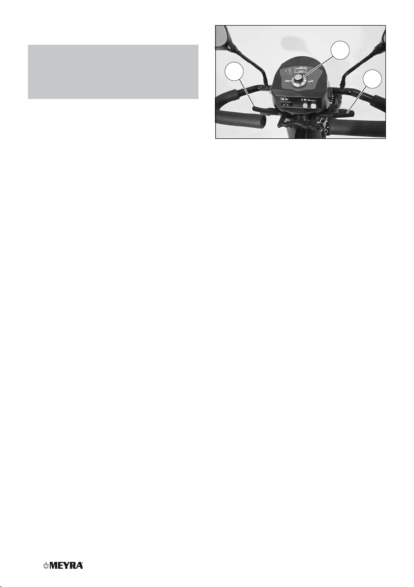
OVERVIEW
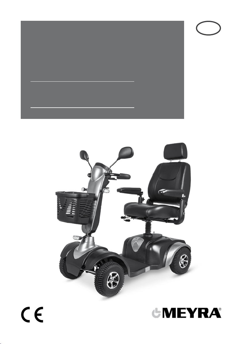
Operating module
The overview shows the operating controls
of the operating module.
Pos. Description
(1) Status indicator
– Control gauge for operational readi-
ness / error display.
(2) Battery voltage gauge
(3) Speed preselection
– Rabbit (highest selectable max. final
speed)
– Turtle (lowest selectable max. final
speed)
(4) Toggle switch turn signal left/right
(5) Lighting ON/OFF
(6) Horn
– When pressing this key a horn signal
sounds.
(7) Battery charging socket
– The battery charging socket is pro-
tected by a cover plate that can be
swivelled to the side.
(8) Hazard warning indicator ON/OFF

11
TIPS FOR ACCIDENT
PREVENTION
Only transfer into or out of the seat when
the Scooter is switched off and the se-
lection lever drive-/push mode is in drive
mode!
– An unintentional motion of the driving
actuator could otherwise let the Scooter
start uncontrolled! – Danger of accident!
First driving practice
☞A low speed is to be selected on the
control panel for first driving practice.
Get accustomed in steps to the driving
behaviour of the Scooter.
☞Carry out a short braking and steering
test at a very low speed immediately
after the start of motion.
Safety information
☞Curves and slopes are to be carried out
at adapted speed. – Danger of over-
turning.
☞There is a danger of tilting when driving
backwards on ramps!
☞The support castors can touch the
ground while driving down, e.g. in front
of the edge of an obstacle which can
cause the drive wheels to lift off the
ground. – The Scooter will the loose its
manoeuvrability!
☞Do not switch off the Scooter whilst it is
in motion. The Scooter will then switch
off and stop immediately.
☞The driving behaviour can change by
adding or removing accessories/com-
ponents.
☞Do not expose the Scooter to extreme
weather.
☞Temperature influence through lamps,
sun and other sources of heat can dam-
age the upholstery and revetment or
heat it up so much, that it can cause
burns when they come in contact with
bare skin.
☞Protect bare as well as heat sensitive
skin accordingly.
☞Mobile phones and other radio com-
munication devices should, for safety
reasons, only be used when the Scooter
is switched off.

12
HANDLING OF THE
SCOOTER
Securing the Scooter
The Scooter is to be secured as follows to
prevent it from rolling off unintentionally:
1. Slide the selection lever for drive-/push
mode toward the back into drive mode.
2. Pull out the drive key.
Functional checks
The functions and safety of the Scooter
must be checked before the start of each
journey.
Driving
You determine the speed and driving di-
rection yourself when driving through the
movement of the driving actuator and the
maximum top speed setting of your scoot-
er.
BRAKES
Brake the Scooter down carefully and in
time. This is especially the case when driv-
ing in front of people and while driving
downhill!
Service brake
The motor works electrically as an operat-
ing brake and decelerates the scooter softly
and jerk-free to a standstill.
Braking down the Scooter
For allotted braking of the scooter slowly
guide the driving actuator back to the cen-
tre position (zero-setting).
☞The scooter stops after a shortest dis-
tance after releasing the driving actu-
ator.
Braking distance
In delivery condition the braking distance
is according to the maximum values of EN
12184:
– 1.0 m with 6 km/h.
The braking distance may get longer de-
pending on the road conditions or the con-
dition of the tyres.
Parking brake
The parking brakes are only effective when
the selection lever drive-/push mode is set
to drive mode. They disengage automatical-
ly when the wheelchair starts off.
The parking brakes are manually disen-
gaged by switching the selection lever
drive-/push mode to push mode.

1
2
13
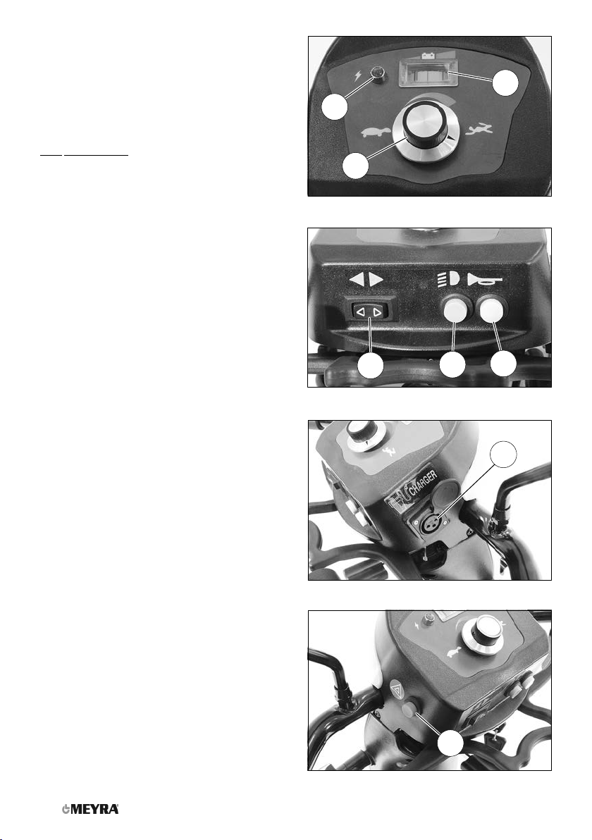
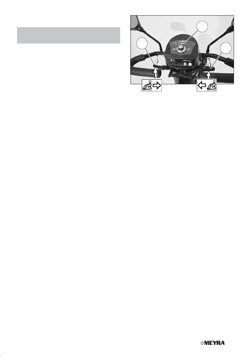
Locking the brakes
It should not be possible to push the
Scooter forward when the brakes are en-
gaged.
Do not switch to push mode while driving
on slopes.
To engage the brakes slide the selection
lever drive-/push mode slightly inward and
as far as possible toward the back into drive
mode [1].
☞Activation of the selection lever is in-
tended for an accompanying person.
Releasing the brakes
To disengage the brakes slide the selection
lever drive-/push mode slightly inward and
as far as possible toward the front into push
mode [2].
☞Activation of the selection lever is in-
tended for an accompanying person.
2
1
14
DRIVE-/PUSH MODE
Only switch the Scooter to push mode
when it is standing still for positioning
or in case of emergencies, but not on
slopes/hills.
After push mode do not forget to switch
the drive back to drive mode. Danger of
uncontrolled Scooter movement if you do
not do this!
Selecting the push mode
1. Switch off the operating module be-
cause the pushing will otherwise be
made difficult by the electric system.
☞Therefore observe chapter Operat-
ing module-functions on page 16.
2. Disengage the brakes [1].
☞Therefore observe chapter Releasing
the brakes on page 13.
☞The Scooter can now be pushed.
Selecting the motor mode
1. Activate the brakes [2].
☞Therefore observe chapter Locking
the brakes on page 13.
2. Switch the operating module on.
☞Therefore observe chapter Operat-
ing module-functions on page 16.
☞The Scooter is now ready for use
again.
1
2
3
15
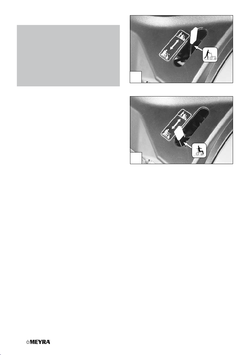
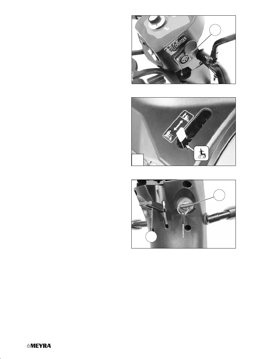
DRIVING LOCK
(1) Driving lock
(2) Key position 0 (OFF)
(3) Key position 90° (ON)
DRIVE KEY
Position OFF
The driving key is inserted as far as possible
into the driving key socket (2).
– For switching off turn the driving key
from the position (3) as far as possible
counter clockwise (2).
☞The Scooter is switched off.
Position ON
The driving key is inserted as far as possible
into the driving key socket (2).
– For switching on turn the driving key
from position (2) clockwise by 90° (3).
☞The drive mode is enabled.
Locking the Scooter
In order to secure the Scooter against un-
permitted or unwanted use, switch off the
Scooter and pull out the driving key (1).
☞The selection lever drive/push mode is
in drive mode position.
– For this observe chapter Drive-/push
mode on page 14.

1
2
16
OPERATING
MODULE-FUNCTIONS
Battery charging socket
Do not insert other objects into the bat-
tery charging socket. – Danger of short
circuit!
To charge the batteries first switch off the
operating module. Then insert the plug of
the battery charger into the charging socket
(1) on the front of the operating module.
Switching on the Scooter
Do not move the driving actuator during
the system test.
To switch the scooter on turn the driving
key 90° clockwise (2).
– The electronic system now performs a
system test.
☞The scooter is ready when the control
gauge (3) is permanently lit.

3
4
3
5
17
Battery voltage
The battery indicator displays the battery
voltage after the system test performed by
the electronic system after the operating
module has been switched on (4).
With reducing battery voltage the display
needle reaches less towards the right.
Battery gauge
The battery gauge (4) displays the existing
battery voltage as follows:
The colours mean:
Green Batteries charged
☞The charging condition
corresponds to a display
of 0 - 100%.
Yellow Recharging recommended.
Red Recharge batteries immedi-
ately.
☞An accurate battery indication is only
given during travel on a level surface.
☞Uphill/downhill travel falsifies the
indication.
Evaluation
The exactness of the battery gauge de-
pends for example on the temperature, age
and strain on the battery is therefore sub-
ject to certain restrictions.
The kilometric performance (range) of the
Scooter should be tested at least once.
2
11
18
Preselected final speed
Danger of accident due to unsuitable set-
ting of the preselected speed!
Drive especially carefully during the first
journeys!
The speed is defined by motion of the actu-
ator (1) as well as the preselected final speed
through the turning knob (2).
Preselecting the nal speed
When switching on the Scooter the set
speed is preselected.
The final speed is adjusted continuously
through the turning knob (2) (also during
driving).
Increasing clockwise turns of the knob in-
crease the maximum final speed according-
ly from slow (symbol turtle) to fast (symbol
rabbit).
Select a low maximum speed for driving sit-
uations in which you do not feel confident/
safe (e.g. driving in confined spaces, or sim-
ilar).
☞The final speed is to be preselected in
dependence on the personal impres-
sion of the respective driving situation!
☞When driving on ramps, hills or slopes
the speed is to be adjusted to the in-
clination appropriately. Never exceed
the permitted max speed. – Danger of
accident!
21
3
19
Actuator
Only move the driving actuator when the
battery gauge (3) is permanently lit.
The driving speed is determined through
motion of the actuator (1) while driving.
As soon as the actuator is moved the Scoot-
er, depending on the adjustment maximum
final speed, starts driving fast or slow.
Forward driving speed
Move the right side of the driving actuator
lever (1) slowly in the direction of he arrow
until you reach the desired driving speed.
Backwards driving speed
Move the left side of the driving actuator
lever (2) slowly in the direction of the arrow.
☞The final speed is reduced automatical-
ly during rearward travel.
Left/right turns
In order to drive curves, move the steering
column to the right or left with the handles,
depending on the desired curve radius.
Braking down the Scooter
The scooter stops when you let go of the
driving actuator.
For allotted braking slowly guide the driv-
ing actuator back to the centre position (ze-
ro-setting).
1
2
4
3
20
SELECTING THE
OPERATION
In order to obtain operational readiness of
the Scooter the following directions are to
be carried out in the indicated order.
1. Charge the drive batteries via the op-
erating module before the first journey
(1).
☞Therefore observe chapter Recharging
batteries on page 21.
2. Switch the drive motors to the drive
mode [2]. – For this engage the brakes.
☞Observe chapter Locking the brakes
on page 13.
3. Check the position of he steering col-
umn.
In order to position the steering col-
umn, press the adjustment lever (3) up-
ward.
☞The steering column is to be posi-
tioned so that the scooter can be
steered comfortably and safely.
4. Switching on the Scooter
☞Do not insert objects, other than the
driving key, resp. the battery charging
plug into the corresponding sockets.
– Danger of short circuit!
To switch the scooter on turn the driv-
ing key 90° clockwise (4).
☞The scooter is ready when the sta-
tus gauge is permanently lit.
Table of contents
Other Meyra Scooter manuals


