Meyra Ortopedia CL515 User manual

en
Operating manual
Scooter
Model 1.274, CL515

2
Contents
Meaning of the applied markers 5
Introduction 5
List of models 5
Indications / contraindications 5
Acceptance 6
Intended purpose 6
Use 6
Adjustment 6
Combination with manufacturer
foreign products 7
Reinstallment 7
Life span 7
Overview 8
Model: 1.274 8
LCD colour display 9
Control panel 10
Steering column 11
Radio key 11
Symbols of the LCD colour display 12
Keys and symbol of the operating
panel 14
Handling of the scooter 16
Short term parking of the scooter 16
Functional checks 16
Driving 16
Brakes 16
Service brake 16
Braking down the scooter 16
Parking brake 16
Releasing the parking brake in
case of emergency 16
Hand brake 16
Locking the hand brake 16
Releasing the hand brakes 17
Loosening the parking brake 17
Loosening the parking brake 17
Tightening the parking brake 17
Drive-/push mode 17
Selecting the push mode 17
Selecting the motor mode 17
Radio key 18
Switching on the Scooter 18
Switching the scooter off 18
Locking the Scooter 18
Steering column 18
Battery charging socket 18
USB-charging socket 18
Battery voltage 18
Battery gauge 19
Evaluation 19
Preselected final speed 19
Preselecting the maximum speed 19
Accelerator lever 19
Forward driving speed 19
Backwards driving speed 19
Left/right turns 20
Braking down the scooter 20
Selecting the operation 20

3
Pre-operation checks 20
Battery charging condition 20
Recharging batteries 21
Battery charging procedure 21
Seat 21
Turning the seat 21
Removing the seat 21
Attaching the seat 22
Adjustment of the seat height 22
Adjusting the distance seat to tiller 22
Back support 22
Arm supports 22
Swivel up the arm supports 22
Adjusting the arm support angle 22
Remove the arm support 22
Insert and position the arm support 22
Head support 22
Adjusting the headrest height 22
Cup holder 22
Front basket 23
Seat basket (Option) 23
Walking aid holder 23
Support castors 23
Batteries 23
Stillstand for more than four weeks 23
Retaining strap 23
Loading and transportation 24
Loading 24
Ramps and lifting platforms 24
Transport of people inside a motor vehicle24
Reducing the size of the scooter 24
Transport security 25
Maintenance 25
Maintenance 25
Maintenance schedule 26
Wheels 28
Fuses 28
Replacing the fuses 28
Fuse box 28
Lighting 28
Headlights 28
Fault correction 29
Basic safety information 30
Transfer out of the Scooter 30
Reaching for objects 30
Driving on falling, rising or transverse gradi-
ents 30
Crossing obstacles 31
Electrical system 32
Statutory regulations 32
Transport in public methods of
transportation 32
Driving on public highways 32
Cleaning 33
Finish 33
Disinfection 33
Repairs 34
Repairs 34
Customer Service 34
Spare parts 34
Information for extended pauses of
use 34
Disposal 34
Information for the specialist dealer 35
Programming the driving behaviour 35

4
Technical data 35
Tyre pressure of pneumatic tyres 35
Maximum range 36
Hill climbing ability 36
Applied norms 36
Values acc. to ISO 7176-15 for
model 1.274, CL515 36
Further technical data for
model 1.274, CL515 37
Meaning of the symbols on the
washing instruction 38
Meaning of the labels on the scooter 38
Meaning of the symbols on the
type plate 39
Warranty / Guarantee 39
Inspection certificate 41
Warrantee / Guarantee section 42
Inspection certificate for transfer 42

5
MEANING OF THE APPLIED
MARKERS
Safety instructions with a coloured back-
ground are mandatory and need to be ob-
served under any circumstance!
☞This symbol indicates tips and recommen-
dations.
[ ] Reference to a picture number.
( ) Reference to a function element within a
picture.
INTRODUCTION
Read and observe this manual before first
operation.
Children and juveniles should read this doc-
umentation together with their parents re-
spectively a supervisor or accompanying
person before first use.
This operating manual is to help you get accus-
tomed to the handling of the Scooter as well as
to prevent accidents.
☞Please note that the illustrated equipment
variants can deviate from your model.
We have therefore also listed chapters with
options that might not be applicable for your
Scooter. A list of the available options and ac-
cessories can be viewed in the order form of
your Scooter.
Users with visual impairments can find the PDF-
files together with further information on our
website:
< www.meyra.com >.
☞Contact your specialist dealer when re-
quired.
Alternatively users with visual impairments can
have the documentation read out by a helper.
Inform yourself regularly about product safety
and possible recalls of our products in the < In-
formation center > on our website:
< www.meyra.com >.
We have developed a Scooter that complies
with the technical and governmental regula-
tions of medical devices. For information about
a severe accident that can still not be ruled
out completely, please use our E-mail address
governmental agency of your country.
LIST OF MODELS
This operating manual applies to the following
models:
Model 1.274, CL515
INDICATIONS /
CONTRAINDICATIONS
In case of allergic reactions, redness of skin
and/or pressure sores while using the Scoot-
er, contact a doctor immediately.
In order to prevent contact allergies, we rec-
ommend to use the Scooter only when wear-
ing clothes.
The Scooter serves to improve the independ-
ent mobility for people with limitations in mo-
bility not necessarily caused by disease.
The Scooter may not be used in cases of:
– Inability to sit.
– Loss of limbs on arms and legs, that cannot
be compensated by prosthetics.
– Blind people and people with limited eye-
sight that cannot be compensated with
other aids and lead to constraints in daily
life.
– Cognitive limitations and mental retarding,
that rule out the independent use of the
Scooter.
– Influence of impairing medications (ask
your doctor or pharmacist).
– Extreme limitations in balance and/or dis-
orders in perception.
– Contractures to arms and legs that prevent
a safe use of the Scooter.

6
– Circumstances that prevent the individual
use of the control device.
☞To these and other possible risk con-
cerning your Scooter ask your doctor,
therapist or specialist dealer.
ACCEPTANCE
All products are checked for faults in the facto-
ry and packed in special boxes.
☞We nevertheless ask you, immediately after
receipt of the Scooter best while the de-
livery agent is present – to check for any
damages that might have occurred during
transport.
☞The packaging of the scooter should be
stored for a further transport that might
become necessary.
INTENDED PURPOSE
The Scooter serves to improve the independ-
ent mobility for people.
USE
The scooter is driven through the driving
actuator that is integrated into the steering
column.
The general capability of the driver to partic-
ipate in traffic must be given.
Refrain from jerky starts with your scooter.
– Danger of tipping over or tilting!
Do not use the scooter without a mounted
seat!
Avoid driving on inclinations or slopes with
insufficient surface condition.
The Scooter serves solely for transporting
one sitting person. – Other pulling or trans-
porting uses do not comply with its intended
purpose.
The scooter is applicable on level, firm surfaces
and can be used as follows:
– outdoors (e.g. paved paths in parks).
– Never expose the scooter to extreme tem-
peratures and damaging environmental
conditions, such as sunlight, extreme cold
or salty water.
– Sand and other dirt particles can seize on
moving parts and render them without
function.
National regulations might prevent the use on
busses, trains or in aircraft.
☞Inform yourself at the transportation com-
panies concerning limitations.
☞Before going on a flight clarify the specific
transport conditions with your flight agen-
cy and also the legal regulations concern-
ing transport in a plane in your country of
residence as well as at your destination.
Only apply the scooter within the scope of the
specifications and limitation described in chap-
ter Technical data on page 35.
ADJUSTMENT
Always have adaptation and adjustment
work carried out by a specialist dealer.
The scooter offers manifold adjustment possi-
bilities to individual vital statistics. Before first
use an adaptation of the Scooter and a prac-
tical instruction in the functionalities of your
Scooter should be carried out by your specialist
dealer. The adaptation will take into account
the driving experience, the physical limits
of the user and the main place of use of the
scooter. Before first use, check the functionality
of your Scooter.
Should your specialist dealer carry out a re-
vision/reconditioning or make fundamental
changes to your vehicle, without the use of
original spare parts, this under certain condi-
tions may result in a remarketing of your scoot-
er. This will further entail that your specialist

7
dealer might need to conduct new conformity
assessments and tests.
☞We recommend a regular control if the
scooter adjustment in order to ensure a
long-term optimal provision even with
changing illness/handicap patterns of the
user. Especially for children and juveniles
an adjustment every 6 months is recom-
mendable.
☞We recommend regular medical exams in
order to ensure safety for active participa-
tion in traffic.
COMBINATION WITH MAN-
UFACTURER FOREIGN
PRODUCTS
Any combination of your Scooter with compo-
nents not supplied by us generally results in
an amendment to your Scooter. Please inquire
with us if there is a valid combination clear-
ance/release.
REINSTALLMENT
The scooter is suited for reinstallment. With the
building block system the Scooter can be fit to
accommodate different handicaps body sizes.
Before reinstallment the scooter is to undergo
a complete inspection.
☞Hygienical measures required for reinstall-
ment are to be carried out according to a
validated hygienic plan and must include
disinfection.
The service manual, intended for the special-
ist dealer provides information to the rein-
stallment and reinstallment frequency of your
Scooter.
LIFE SPAN
We expect an average life span of about 5 years
for this Scooter, as far as the Scooter is applied
for its designated purpose and all maintenance
and service guidelines. The life span of your
Scooter depends upon the frequency of use,
the application environment and care. The im-
plementation of spare parts can prolong the
life span of the Scooter. As a rule spare parts
are available up to 5 years after production is
discontinued.
☞The indicated lifespan does not constitute
additional guarantee.

11
1 2 3
4
5
7
8
9
12 13 16
17
19
20
22
21
6
10
14 15
18
23
8
OVERVIEW
Model: 1.274
The overview shows the most important components and operating devices of the Scooter.
(15) LCD colour display
(16) Hand brake lever
(17) Indicator front right
(18) Connector socket for charging plug and
USB-plug
(19) Cup holder
(20) Lever for seat lock
(21) Support castor
(22) Ramming guard rear
(23) Rear light
Pos. Description
(1) Head support
(2) Arm support
(3) Steering column
(4) Bracket for front basket
(5) Seat with back support
(6) Headlights
(7) Ramming guard front
(8) Steering wheel
(9) Lever for seat angle adjustment
(10) Lever for back support angle adjustment
(11) Driving wheel
(12) Steering column with driving actuator
(13) Rear-view mirror
(14) Control panel
12 11 10 9 7
1 2 4 5 63
8
9
OVERVIEW
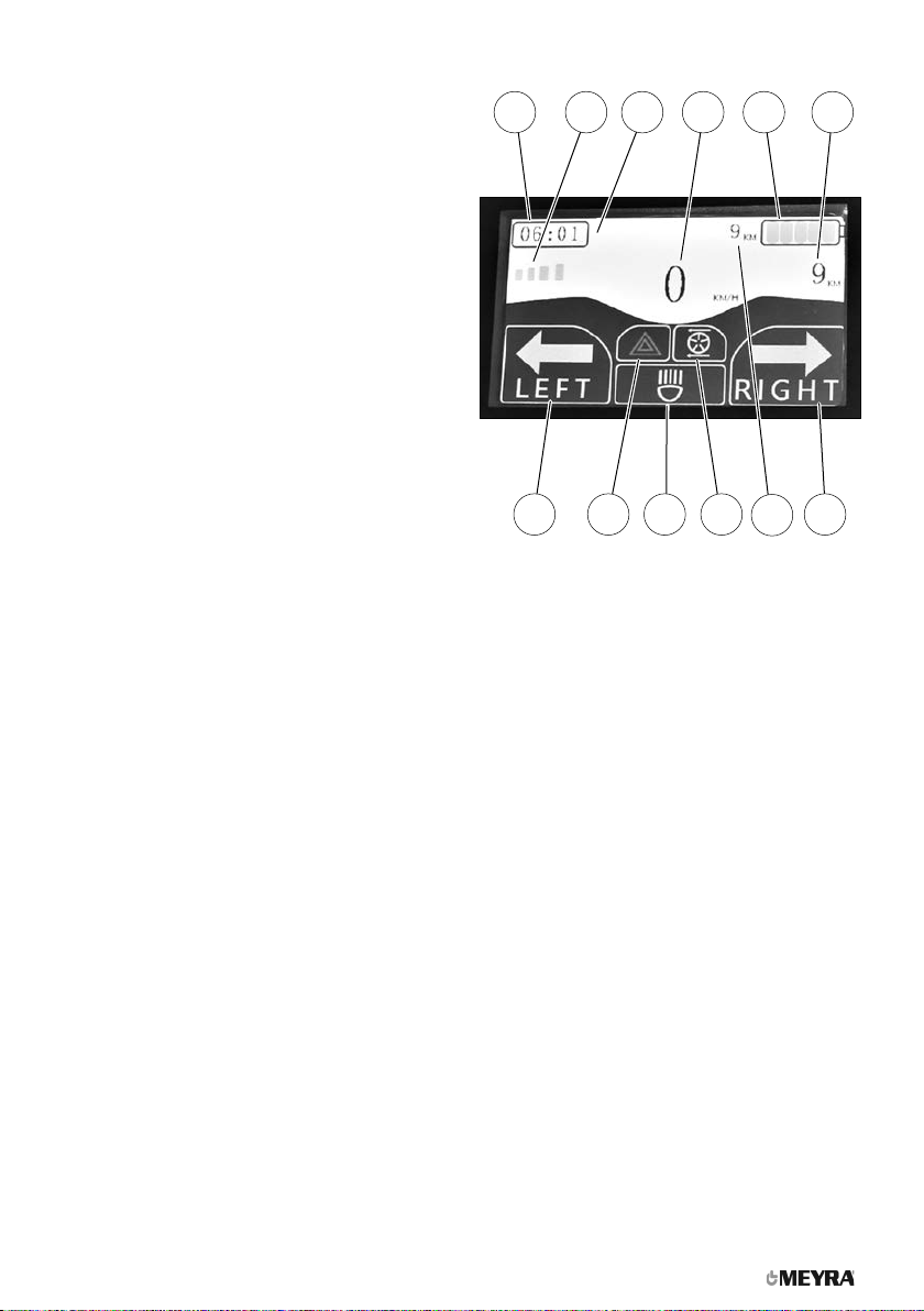
LCD colour display
The overview shows the display in the LCD col-
our display.
Pos. Description
(1) Display of the time
(2) Display of the preselected driving speed
step (max. 6 steps)
(3) Display of the bluetooth symbol with con-
nected device
(4) Display of the currently achieved driving
speed
(5) Control gauge of the battery charging con-
dition
(6) Display of the current day driven kilome-
ters
– The display switches after 999 km to
0 km.
(7) Display right indicator
– The display blinks green with activated
turn signal.
(8) Display of driven kilometres
– The display switches after 99.999 km to
0 km.
(9) Display push mode
– The symbol lights up green when push
mode is activated.
(10) Display lighting
– The symbol lights up green when the
lighting is switched on.
(11) Display hazard warning indicator
– The symbol lights up red when the
warning light is switched on. The dis-
play of the left/right turn signal blinks
green when the warning lights are
switched on.
(12) Display left indicator
– The display blinks green with activated
turn signal.
11 10 9 8 7 6
1 2 3 4 5
10
OVERVIEW
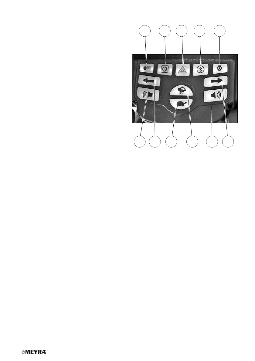
Control panel
The overview shows the operating setting of
the control panel with lighted pressure keys.
Pos. Description
(1) Lighting ON/OFF
– Switches the scooter lighting on/off.
☞View chapter Symbols of the LCD colour
display on page 12.
(2) Settings
– Opening and closing the display to set
the clock.
(3) Hazard warning indicator ON/OFF
– Switches the warning lights on/off.
☞View chapter Symbols of the LCD colour
display on page 12.
(4) Bluetooth on/off
– Switches the bluetooth device connec-
tion on/off.
☞View chapter Symbols of the LCD colour
display on page 12.
(5) Push mode on/off
– With depressed key, switches the
scooter to push mode.
(6) Right indicator on/off
– Switches the turn signal on/off.
☞View chapter Symbols of the LCD colour
display on page 12.
(7) Horn
– When pressing this key a horn signal
sounds.
(8) Speed preselection plus
– Rabbit (highest selectable max. final
speed in step 6, about 100 %)
– Every pressing of the key increases the
speed by one step, about 20 %.
(9) Speed preselection minus
– Turtle (lowest selectable max. final
speed in step 1, about 5 %).
(10) Left indicator on/off
– Switches the turn signal on/off.
☞View chapter Symbols of the LCD colour
display on page 12.
(11) Horn
– When pressing this key a horn signal
sounds.
I
II
5
4
9
8
7
10
11
12
13
6
14
3
16
15
17
11
OVERVIEW
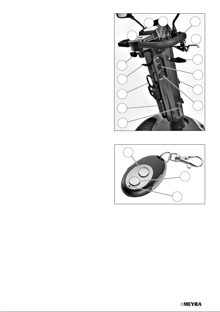
Steering column
The overview shows the operating setting and
components of the steering column.
Pos. Description
(1) Control panel
(2) LCD colour display
(3) Driving actuator for finger operation
(4) Handle bar
(5) Hand brake lever
(6) Right indicator
(7) Battery charging socket
(8) Bracket for utensil basket
(9) USB-charging socket
– The USB-charging socket is protected
by a cover cap that can be swivelled to
the side.
(10) Passive lighting
(11) Socket strip with flat fuses
(12) Cup holder
(13) Locking lever of the steering column
(14) Driving actuator for thumb operation
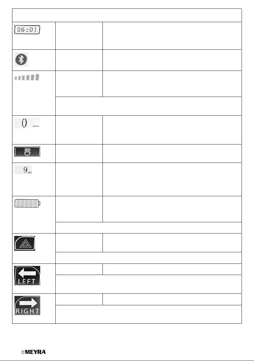
Radio key
Pos. Description
(15) Key OFF
– Switches the scooter off.
(16) Key ON
– Switches the scooter on.
(17) LED-display of the radio connection
– The LED lights up blue with active radio
connection.
12
SYMBOLS OF THE LCD COLOUR DISPLAY
Time Display of the current time.
☞Depending on the set time in the adjustment
screen.
Bluetooth Blue display with active bluetooth connection.
Final speed Display of the preselected final speed.
☞With reducing speed, correspondingly less of the
lighting segments are lit in the 6-step display.
☞View chapter Preselected final speed on page 19.
Speed Display of the currently achieved driving speed.
Lighting ☞The symbol lights up green when the lighting is
switched on.
Total kilo-
metres
☞The display to the left of the battery symbol shows
the driven total kilometers.
☞The display below the battery symbol shows the
driven kilometers of the current day.
Battery charg-
ing condition
Display of the battery charging condition.
☞The reducing battery charging condition, less seg-
ments are lit.
☞View chapter Battery charging condition on page 20.
Hazard warn-
ing signal
The symbol blinks red when the warning light is
switched on.
☞The symbol blinks in the same tact with the indicator.
Left indicator The display blinks green with activated turn signal.
☞The turn signal automatically switches off after 15 blinking signals. A
quick blinking of the LED indicates a defective indicator light.
Right indicator The display blinks green with activated turn signal.
☞The turn signal automatically switches off after 15 blinking signals. A
quick blinking of the LED indicates a defective indicator light.

14
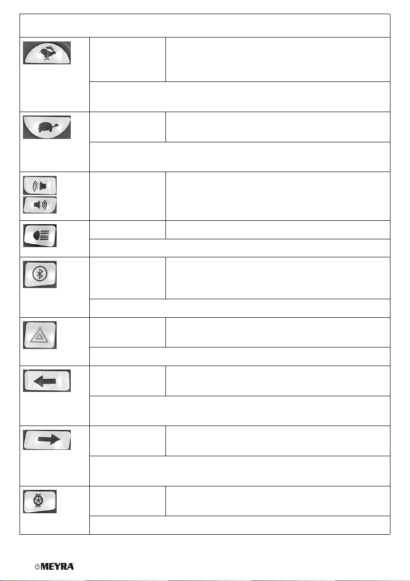
KEYS AND SYMBOL OF THE OPERATING PANEL
Plus key (rab-
bit)
Increases the 6-step final speed by one step on each
pressure.
☞For safety reasons we recommend to only press the < Plus-key >
when the wheelchair is standing still.
Minus key (tur-
tle)
Decreases the 6-step final speed by one step on each
pressure.
☞For safety reasons we recommend to only press the < Minus-key >
when the wheelchair is standing still.
Horn When pressing this key a horn signal sounds.
Lighting Switches the lighting on or off when pressing the key.
☞Display when lighting is switched on.
Bluetooth Switches the bluetooth device connection on or off
when pressing the key.
☞Display with active bluetooth connection.
Hazard warn-
ing signal
Switches the hazard warning signal on or off when
pressing the key.
☞The display blinks in the same tact with the indicator.
Left indicator Switches the indicator lights on or off when pressing the
key.
☞The turn signal automatically switches off after 15 blinking signals. A
quick blinking of the LED indicates a defective indicator light.
Right indicator Switches the indicator lights on or off when pressing the
key.
☞The turn signal automatically switches off after 15 blinking signals. A
quick blinking of the LED indicates a defective indicator light.
Push mode Switches the scooter into push mode for the duration of
keeping the key pressed.
☞Display while push mode is switched on.

15
KEYS AND SYMBOL OF THE OPERATING PANEL
Settings Opens the screen "Time".
The hours and minutes are set by pressing the turn sig-
nal and horn key left/right.
With each pressing of the key the hour display increases.
With each pressing of the key the hour display decreases.
With each pressing of the key the minute display increas-
es.
With each pressing of the key the minute display de-
creases.
Through the rabbit and turtle key the setting is selected
or cancelled.
Selects (saves) the time setting upon key activation.
☞The drive mode screen is displayed again.
Selects (saves) the time setting upon key activation.
☞The drive mode screen is displayed again.

16
HANDLING OF THE SCOOTER
Short term parking of the scooter
The scooter is to be secured as follows to pre-
vent it from rolling off unintentionally:
1. Switch the scooter off with the radio key.
Functional checks
The functions and safety of the scooter must
be checked before the start of each journey.
Carry out a short braking and steering test at a
very low speed immediately after the start of
motion.
☞Do not switch off the Scooter whilst it is
in motion. The scooter will then switch off
and stop immediately.
Driving
You determine the speed and driving direction
yourself when driving through the movement
of the actuator and the maximum top speed
setting of your Scooter.
☞The driving behaviour can change by add-
ing or removing accessories/components.
BRAKES
Brake the scooter down carefully and in time.
This is especially the case when driving in
front of people and while driving downhill!
Service brake
The motor works electrically as a driving brake
and decelerates the Scooter softly and jerk-free
to a standstill.
Braking down the scooter
For allotted braking of the Scooter slowly guide
the actuator back to the centre position (ze-
ro-setting).
☞The scooter stops in shortest distance after
releasing the actuator.
Parking brake
The parking brake releases automatically dur-
ing start-off.
The parking brake is released by hand, through
pressing the push mode key.
Releasing the parking brake in case of
emergency
If the scooter can no longer be switched on,
the parking brake can be released by folding
over the hand lever of the magnetic brake.
☞A braking of the scooter is now only possi-
ble with the handbrake.
Hand brake
For optimal braking effect the disc brake is to
be kept free of grease, oil, gunge and dust.
– Danger of accidents!
The brake performance reduces with the
wear on the brake pads.
Any decrease in braking performance must
be repaired immediately by your specialist
workshop.
The handbrake is fit with a disc brake on each
rear wheel.
Locking the hand brake
1. Pull the brake lever (1on page 43).
2. Press the locking button (2on page 43)
down.
☞It should not be possible to push the
Scooter forward when the handbrakes are
engaged.

17
Releasing the hand brakes
Slightly pull the brake lever (1on page 43).
– The locking button (2on page 43) jumps
out of the catch.
Release the brake lever. – The handbrake is dis-
engaged and the scooter ready for operation.
Loosening the parking brake
A loosening of the parking brake is only in-
tended through the specialist dealer!
Loosening the parking brake is only to be
conducted in emergency situations and after
consulting the specialist dealer. – Danger of
accidents!
Only loosen the parking brake when the
handbrake is activated!
The handbrake is fit with a disc brake on each
rear wheel.
Loosening the parking brake
1. Tighten the handbrake and lock it.
2. Slide the brake lever (3on page 43) of
the parking brake down [4on page 43].
☞The parking brake is loosened and the
scooter may not let itself be moves against
the locked handbrake.
Tightening the parking brake
1. Slide the brake lever (3on page 43) of
the parking brake up [5on page 43].
2. Release the handbrake.
☞It should not be possible to push the
Scooter forward when the parking brakes
are engaged.
Drive-/push mode
Only switch the scooter to push mode or
push it when it is standing still for positioning
or in case of emergencies, but not on slopes/
hills.
☞The parking brake is switched off when
push mode is activated.
☞Grab onto the steering lever to shunt the
scooter.
Selecting the push mode
To establish push mode, press the pressure key
(1) for push mode.
☞Push mode is activated as long as the
pressure key (6on page 43) is being
pressed.
☞The symbol (7on page 43)lights up
in green for the duration of the activat-
ed push mode.
☞The scooter can now be pushed.
Selecting the motor mode
To establish drive mode, release the pressure
key for push mode (6on page 43).
☞The symbol (7on page 43) goes
dark.
☞The scooter is now ready for use.

18
RADIO KEY
The LED (8on page 43) is lit in blue as long
as the scooter is being used.
Protect the radio key from getting damp or
wet.
The scooter is supplied with two radio keys [11
on page 43].
Switching on the Scooter
To switch the scooter on press the pressure
button (9on page 43) of the radio key.
☞The scooter receives the radio signal to
switch on.
☞The scooter is on, when the colour display
(12 on page 43) is shown.
☞The electronic system now performs a
system test.
When the battery gauge (13 on page 43)
shows a permanent light, the scooter is ready
for operation.
Switching the scooter off
To switch the scooter off press the pressure
button (10 on page 43) of the radio key.
☞The scooter receives the radio signal to
switch off.
☞The scooter is off, when the colour display
(12 on page 43) goes out.
Locking the Scooter
To secure the scooter against unauthorised or
unwanted use, first switch the scooter off with
the radio key [11 on page 43]. Afterwards
switch the main fuse (14 on page 44) off with
the circuit breaker.
☞The scooter is separated from the power
source.
☞Therefore observe chapter Fuses on
page 28.
STEERING COLUMN
Battery charging socket
Do not insert any objects other than the bat-
tery charging plug into the battery charging
socket. – Danger of short circuit!
To charge the batteries, fist switch the scooter
off with the radio key and then insert the plug
of the battery charger into the charging socket
(15 on page 44) on the steering column.
USB-charging socket
Do not insert other objects than a USB-plug
into the USB-charging socket. – Danger of
short circuit!
To charge a device with USB-charging cable,
first swivel the cover cap (16 on page 44)
back counterclockwise (17 on page 44).
After charging swivel the cover cap (17
on page 44) forward clockwise (16 on
page 44).
Battery voltage
After switching the scooter on with the radio
key [11 on page 43] the battery gauge (13 on
page 43) shows the battery voltage after the
system test.
With reducing battery voltage, less light seg-
ments are shown.

19
Battery gauge
The battery gauge (13 on page 43) displays
the existing battery voltage as follows:
The colours mean:
Green Batteries charged
☞The charging condition
corresponds to a display of
0 – 100%.
Yellow Recharging recommended.
Red Recharge batteries immediately.
☞An accurate battery indication is only given
during travel on a level surface.
☞Uphill/downhill travel falsifies the indi-
cation.
Evaluation
The exactness of the battery gauge depends
for example on the temperature, age and strain
on the battery is therefore subject to certain
restrictions.
The kilometric performance (range) of the
scooter should be tested at least once.
Preselected final speed
Danger of accident due to unsuitable setting
of the preselected speed!
Drive especially carefully during the first jour-
neys!
The speed is determined through the motion
of the actuator (18 on page 44) as well as
the preselected final speed (19 on page 44)
through the pressure keys rabbit (20 on
page 44) and turtle (21 on page 44).
Preselecting the maximum speed
When switching on the Scooter the set speed is
preselected (19 on page 44).
The final speed is set through the pressure keys
(20 on page 44)+(21 on page 44) (also
while driving).
Each press of the key increases or decreases
the selectable maximum final speed accord-
ingly from slow (turtle symbol) to fast (rabbit
symbol).
Select a low maximum speed for driving situ-
ations in which you do not feel confident/safe
(e.g. driving in confined spaces, or similar).
☞The final speed is to be preselected in de-
pendence on the personal impression of
the respective driving situation!
☞When driving on ramps, hills or slopes the
speed is to be adjusted to the inclination
appropriately. Never exceed the permitted
max speed. – Danger of accidents!
Accelerator lever
Only move the actuator when the battery
gauge (13 on page 43) displays a perma-
nent light.
The driving speed is determined through mo-
tion of the actuator (22 on page 44)/(23 on
page 44) while driving.
As soon as the actuator is moved the Scooter,
depending on the adjustment maximum final
speed, starts driving fast or slow.
Forward driving speed
Move the right side of the driving actuator le-
ver (22 on page 44) slowly in the direction
of he arrow until you reach the desired driving
speed.
Backwards driving speed
Move the left side of the driving actuator lever
(23 on page 44) slowly in the direction of the
arrow.
☞The final speed is reduced automatically
during rearward travel.

20
Left/right turns
In order to drive curves, move the steering col-
umn to the right or left with the handles, de-
pending on the desired curve radius.
Braking down the scooter
The scooter stops when you let go of the driv-
ing actuator.
For allotted braking slowly guide the driving
actuator back to the centre position (zero-set-
ting).
SELECTING THE OPERATION
The functions and safety of the scooter must
be checked before the start of each journey.
Only get into, resp. out of the seat when the
scooter has been previously switched off
with the radio key.
☞An unintentional motion of the driving
actuator could otherwise let the Scooter
start uncontrolled.
In order to obtain operational readiness of the
scooter the following directions are to be car-
ried out in the indicated order.
☞Before first use charge the drive batteries
through the battery charging socket (15
on page 44) on the steering column.
– Therefore observe chapter Battery charg-
ing socket on page 18.
1. Selecting the motor mode.
☞Observe chapter Selecting the motor
mode on page 17.
2. Check the position of he steering column.
☞To position the steering column, press
the adjustment lever (24 on page 44)
downward.
– In doing so, keep hold of the handle
bars with one hand, in order to prevent
unintentional snapping forward.
☞The steering column is to be positioned
so that the scooter can be steered
comfortably and safely.
3. Switch on the Scooter.
☞To switch the scooter on press the pres-
sure button (9on page 43) of the ra-
dio key.
☞When the battery gauge in the colour
display shows a permanent light, the
scooter is ready for operation.
☞If the scooter is not used for more than
10 minutes, the LCD display switches
off.
– For further use the scooter must be
switched on again.
PRE-OPERATION CHECKS
Before starting to drive, the following should
be checked:
4. The battery charging condition (13 on
page 43).
5. The preselected setting of the preselecta-
ble final speed (19 on page 44).
☞Therefore observe chapter Preselected
final speed on page 19.
Battery charging condition
After activation the battery gauge (13 on
page 43) shows the battery charging condi-
tion. With reducing battery capacity the num-
ber of lit segments reduces.
☞The displayed value depends on the sur-
rounding temperature, the age of the bat-
tery as well as their type of strain and is
therefore to be observed with limitations.
☞If the red light segment of the battery
gauge is blinking, the batteries should be
charged immediately.
☞View chapter Battery voltage on page 18
and chapter Fault correction on page 29.
This manual suits for next models
1
Table of contents
Other Meyra Scooter manuals


