MFC International RC4000 User manual
1
© MFC International 2017
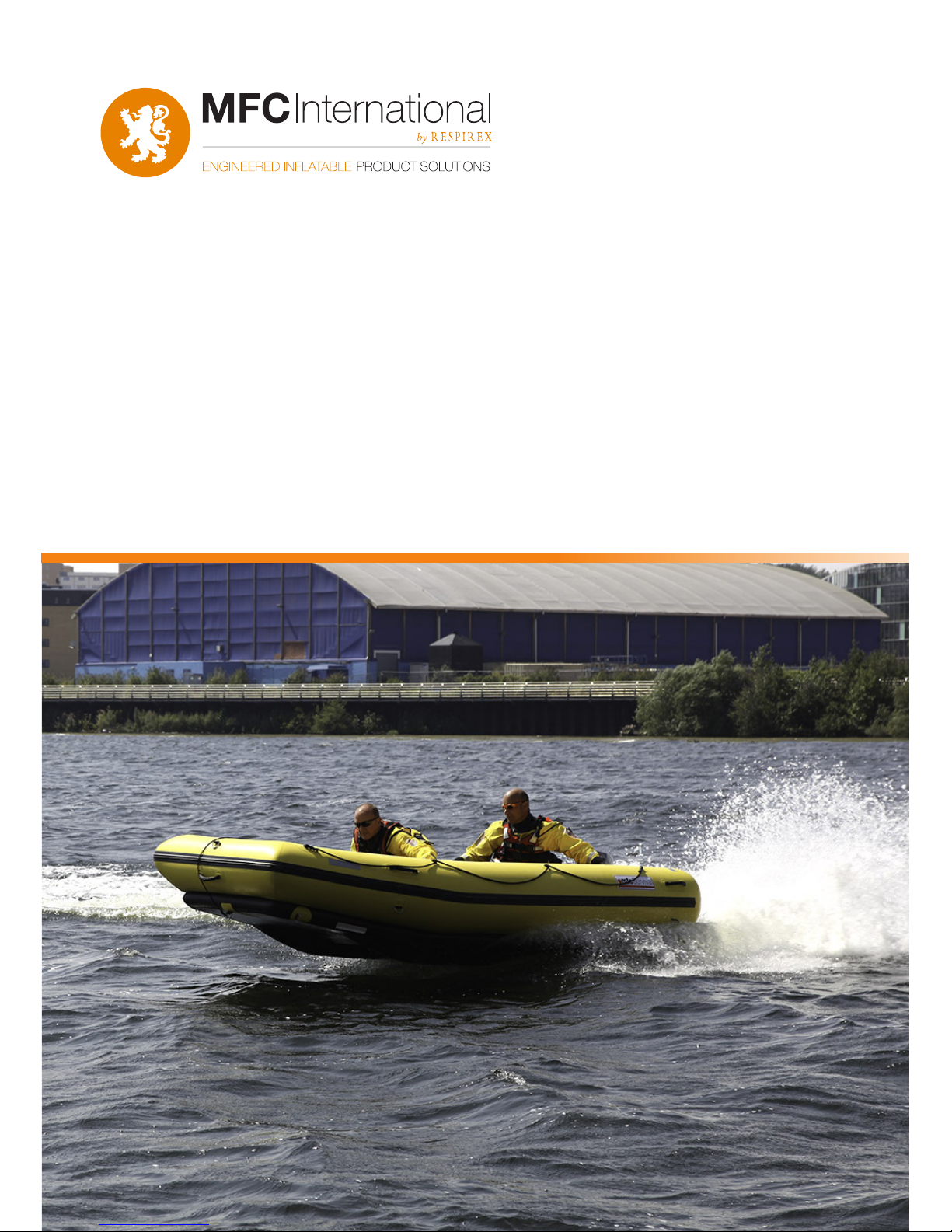
Product Manual
RC4000 Rescue Craft
Community Design number: 2520494

2
© MFC International 2017
Technical data / Capacity Parts
Parts List
Materials list
Operational instructions
Packing
Storage
Maintenance & Test Procedures
Repairs
3
4
5
6
9
9
10
11
WARNING: Carefully read this manual before operating
NOTICE: The manufacturer takes no responsibility for the
consequences of actions not complying with the instructions
given in this manual.
Index

3
© MFC International 2017
RC4000
No. of persons 10
Length (cm) 400
Width (cm) 200
Height (cm) 80
Tube diameter (cm) Stern
Bow
48
36
Floor Thickness (cm) 12.5
Working pressure - Tube (bar) 0.2
Working pressure - Floor (bar) 0.4
Number of Chambers 4(tube) +oor
Capacity (kg) 800
Air requirement (litres) 2900
Pack size L x W x H (cm) 140x50x35
Packed Weight inc. Paddles (kg) 62
Max Motor power 22.1 Kw
Max engine,
short shaft (Hp)
25/30
Max engine
weight (kg)
65
Recommended Regulator Type 646 2 bar
Note: all dimensions are accurate to ± 3% and all weights are accurate to ± 5%
SCOPE OF USE. Category D.
The Rescue Craft is designed for use in “sheltered waters” in wind speeds up to and
including Beaufort scale 4 with a signicant wave height (H1/3; in metres) up to and
including 0.5m.
Technical Data

4
© MFC International 2017
Parts list

5
© MFC International 2017
Item Description
1 Buoyancy tube Hypalon coated polyester - yellow
2Baes Hypalon coated polyester
3Inatable oor Neoprene- coated drop thread - black
4Inate/Deate valves Leaeld D7 - Black Acetal
5Relief Valves Leaeld A6 - Black acetal
6Rubstrake Nitrile/PVC - 70mm wide black
7 Carrying handle Hypalon coated polyester, webbing strap/rubber handle
8 External Lifeline 10mm Diameter 3 strand rope - Black
9 Keel Neoprene coated crop thread - Black
10 Towing patch Hypalon coated polyester, 316 s/s ‘D’ ring
11 ‘D’ Ring patch Hypalon coated polyester, 316 s/s ‘D’ ring
12 Transom Marine ply, 38mm. PU painted
13 Towing ‘U’ Bolts 316 Stainless steel
14 Motor clamp plate Cast aluminium
15 Drain port and plug Acetal moulding
16 Reective strips 50mm Reexite
17 Logo Label White vinyl digitally printed
18 Capacity Label White vinyl digitally printed
19 Inate/Deate label White vinyl digitally printed
20 Paddle retainers Hypalon coated polyester, Webbing strap, velcro
21 Tank retainers hypalon coated polyester, webbing strap with buckle
22 ‘D’ Ring patch (line control) Hypalon coated polyester, 316 s/s ‘D’ ring
23 Drain sleeve Nylon ange moulding, Neoprene coated polyester sleeve
24 Paddles (not shown) Alloy shaft, HDPE blade, T handle
25 Valise (not shown) PVC coated polyester - Orange
26 HP ination hose (not
shown)
1.0m Reinforced hose c/w C7 valve adaptor
27 Repair Kit (not shown) 70ml Neoprene adhesive, Hypalon patches x4
Materials list

6
© MFC International 2017
1. INFLATION
1.1 At deployment point, select best possible at debris-free site.
1.2 Unpack the Rescue Craft from its valise and unroll.
1.3 Prepare for Ination:-
a) Fix regulator to cylinder and connect delivery hose to regulator.
b) Remove dust cap from inate/deate valve in Inatable oor and Buoyancy tube.
Ensure the central valve diaphragms are closed; i.e. the internal spindle is raised. (push
and turn to release)
1.4 Connect cylinder to oor, Hold delivery hose tight into ination valve and inate until
relief valve activates. Close cylinder valve. Do not release hose during ination.
1.5 Connect cylinder to Buoyancy tube at one stern end using the ination hose. Hold
delivery hose tight into ination valve and inate until the relief valve activates.
Wear gloves to protect hands from possible frost damage from ination gas.
Close cylinder valve. Repeat for remaining stern chamber followed by both bow
chambers of buoyancy tube. Do not release hose during ination.
Warning: Failure to do this may result in personal injury
1.6 Ensure dust caps are replaced to prevent ingress of dirt and water.
2. TYPE OF MOTOR AND ADJUSTMENT
2.1 Motor power - The maximum motor power is listed in the Technical Data table.
Warning: Never use a motor power higher than specied in the technical data table.
This could cause loss of control which may result in personal injury.
2.2 Motor weight - The motor weight has a great inuence on the planning, stability
and performance of the Rescue Craft.
2.3 Motor shaft length - The Rescue Craft is to be tted with a Short shaft motor.
3.0 Fitting the motor - Fit the motor in the centre of the cut out in the transom.
Tighten the motor clamp bolts onto the motor clamp plate until they are hand tight.
Secure the motor to the eye of the clamp plate with a cable or strong cord. Check and
re-tighten the motornclamps after approximately 10 minutes of use. All motors above
4 Hp. are tted with an emergency stop switch lanyard which must always be used as
instructed in the motor manual.
Note: The motor must be tted and used in accordance with the motor
manufacturer’s instructions.
4.0 Motor position (trim) - As a general rule the recommended trim angle should be set
so the axis of the propeller shaft is parallel with the water surface when the craft
is at operational speed. Trim motor closer to transom when craft is lightly loaded or going
into wind.
Operational Instructions

7
© MFC International 2017
The Rescue Craft generally works best with the tilt / trim pin 3 holes out from the
transom.
Warning: Only make changes to the trim position with the motor switched o.
Failure to do this may result in personal injury.
3. DEPLOYMENT & USE
3.1 A visual risk assessment of the operating conditions should be carried out prior
to deploying the craft.
3.2 For safe operation of the Rescue Craft it should only be operated by a
minimum of the helmsman plus one crew member.
The preferred location for the crew is positioned centrally just aft of the kink in the
buoyancy tubes and oor, holding on to the internal grab handles.
If the operational conditions warrant, an additional crew member should also be used.
Warning: During use on water, mud or suspect surfaces, personnel should wear
a ”Lifejacket” or Personal Floatation Device.
Always use the Emergency Stop Switch lanyard supplied with the outboard
motor. This is to prevent a runaway boat if the operator falls overboard.
Wear it around your wrist or securely attached to your clothing.
Ensure you have sucient fuel and oil for your anticipated operational
requirements and that the fuel tank is secured.
Ensure you carry paddles on board in case of motor failure.
Avoid the risk of explosion or re hazard. Ensure the fuel system is in good
condition and properly maintained.
Avoid persons smoking near the fuel system, especially when refuelling.
If fuel spills onto the oor of the craft wash o with water.
Take care when docking. Arms and legs may be injured if they are outside
the craft.
Aggressive docking may cause damage to the craft, resulting in air loss.

8
© MFC International 2017
Warning: Avoid contact with sharp or abrasive objects as they may puncture the
fabric causing a loss of buoyancy.
Stability. Wherever possible evenly distribute the weight of persons on
the Rescue Craft to avoid instability that may lead to poor performance
or capsize.
Do not exceed the authorised number of persons or weight.
Casualties should not be seated on the buoyancy tube as they may fall
back into the water and drown. Casualties should be seated facing each
other across the inatable oor holding onto the lifelines for security.
No bow riding, if the person falls they may get hit by the propeller
Keep clear of swimmers and divers. Shut o the motor when operating
near persons in the water.
Avoid sharp turns at high speed. If craft is lightly loaded, crew should
lean into the turn as if riding a motorbike to keep the inside keel
pressed into the water.
3.3 Towing the Rescue Craft - The craft may be towed behind a parent craft
at a maximum speed of 5 mph. The craft must be towed with the tow line attached
to the towing patch on the bow. The length of tow line should be adjusted to suit the
conditions. Remove or secure any loose equipment before towing.
If the craft is to be towed in rough water, over mud or for an extended time, an
additional tow line should be attached to a bridle secured between the ‘D’ ring
patches on either side of the oor in the bow.
3.4 Towing another craft - If another craft has to be taken in tow, the tow line
should be connected to a bridle attached to the ‘U’bolts in the transom. Only use a
speed appropriate to the conditions and the craft being towed.
Remove or secure any loose equipment in the towed craft before towing it.
3.5 Tandem boat control- An additional ‘D’ring patch is tted on top of the
bow and 4(four) internal control line ‘D’ring patches are tted to the oor for this
purpose. These can also be used in conjunction with the ‘U’bolts in the transom.
3.6 Control lines - When the Rescue Craft is used for control line operation,
use lines attached to the ‘D’ ring patches on both sides of the inatable tube to
manoeuvre and/or secure the Rescue Craft to convenient tie points on the bank/
shore.
3.7 Boarding from the water - The inatable oor extends behind the transom
either side of the motor and may be used to assist boarding. On board rescue
personnel should assist less able casualties.
Warning: Ensure the motor is switched o before attempting to board the
Rescue Craft in this way. Propellers can cause serious injury.

9
© MFC International 2017
3.8 Lifelines are tted for survivors to hold on to.
3.9 Hull drainage- A high volume drain sleeve and a drain port with removable plug
are tted in the transom for evacuation of water.
3.10 Manoeuvring without power- The craft can be manoeuvred in calm conditions
by two persons using paddles. It can also be manoeuvred in shallow water by persons
walking alongside holding the carrying handles.
3.11 Carrying handles - The Rescue Craft should only be carried by the moulded
handles provided (2 each side + bow). Do not use the lifelines.
Caution: Do not drag the Rescue Craft, as this may puncture the fabric causing a
loss of buoyancy.
Warning: The tting of a motor of greater power than the maximum specied is
not permitted. Modication to the Rescue Craft is not permitted without prior
written approval from MFC International Ltd.
Any non-approved modication will invalidate the warranty and may result in
personal injury or death.
1. After every use, especially on mudats, the craft should be hosed down in its
inated state, to remove as much debris as possible.
2. Allow the craft to become as dry as possible before packing.
3. Lay the craft on a clean, debris free area.
4. Deate the craft. This is achieved by depressing the central spindle in all the
ination and deation valves, (push and turn to lock open).
5. Roll the craft from bow to stern to expel as much air as possible.
Close inate/deate valves and replace dust caps.
Caution: To prevent possible damage, do not walk on the deating Rescue craft to
expel the air.
6. Un-roll the craft to its full length once again. Fold each side of the buoyancy
tube towards the centre of the oor. Fold transom forward, at onto oor. Check
buoyancy tubes are tucked neatly under transom.
7. Fold oor and ends of buoyancy tube on top of transom and roll towards the bow,
taking care to maintain the width of the roll.
8. Lay the valise on the ground as an ‘open box’ and place Rescue Craft into valise.
Close valise and secure straps.
9. On return to base, ush the motor through with clean fresh water in accordance
with motor manufacturer’s instructions.
Packing

10
© MFC International 2017
1. On return to base the Rescue Craft should be unpacked, inated and left to dry.
2. When it is completely dry it should be checked for wear or damage. If none is
found it should be repacked in the valise.
3. If any damage is found it should be repaired immediately in accordance with
the repair instructions.
4. Where possible the packed Rescue Craft should be stored on the oor or
suitable shelving, ensuring no damage can be caused by its proximity to other items
of equipment.
Maintenance & Test Procedures
1. GENERAL
It should be noted that, due to the type of fabrics used in its construction, when
the Rescue Craft is wet, there may sometimes be visual evidence of miniscule
white bubbles, which form a line of froth at the seams and joints of the unit. This is
recognised within the industry as ‘lateral leakage’, and is simply air that is trapped
in the layer of nylon between the rubber coatings, forcing its way to the nearest
available edge of the fabric. This type of leakage will not aect the performance of
any inatable product over the course of an operational procedure, and can be safely
ignored.
However, if there is evidence of large, transparent bubbles, this is clearly evidence of
a leak that must be repaired at the earliest convenience.
The following is a recommended regime for maintenance & test.
2. QUARTERLY
2.1 Check control equipment as per relevant manual.
2.2 Inate Rescue Craft to working pressure.
2.3 Check audible relief valve operation.
2.4 Whilst ination system is charged, check connections and valves using brush and
soapy water.
2.5 When relief valve has operated, and the unit is at working pressure; it can be left to
stand for a length of time that would be comparable to an operational situation
(e.g. 2 to 3 hours.)
2.6 After this time, the Rescue Craft should still be rm.
2.7 If it has become soft, the air-loss should be located by applying a soapy-water
solution.
Storage

11
© MFC International 2017
2.8 Any signicant leaks (See 1 above) should be marked and repaired using
the repair kit provided.
2.9 Maintain motor and fuel system in accordance with motor
manufacturer’s recommendations.
3. RECOMMENDATIONS.
Rescue Craft should undergo an annual test carried out by the manufacturer, or
people certied by MFC International Ltd. If in doubt contact the service department.
Repairs
As a general rule, punctures and other damage will need to be assessed in two categories: a)
that which is repairable at the base, or b) serious damage that will need to be repaired by MFC
International Ltd.
a) Repairs that are manageable at the base workshops will be minor punctures to any
area of the craft. These can normally be repaired by the application of a small repair
patch.
b) Repairs that should be carried out by MFC will be the more serious kind, such as
damaged valves, badly torn fabric (either on the sidewalls or the at surfaces) and the
replacement of damaged ttings.
If in doubt as to the extent of the damage and the level of repairs necessary, please contact :-
MFC International
Naval Yard
Tonypandy
Rhondda Cynon Ta
CF40 1JS
T. +44 (0) 1443 433 075
F. +44 (0) 1443 420 448
www.mfc-international.com
A Respirex International Limited Group Company

MFC International
Naval Yard
Tonypandy
Rhondda Cynon Ta
CF40 1JS
T. +44 (0) 1443 433 075
F. +44 (0) 1443 420 448
www.mfc-international.com
A Respirex International Limited Group Company SA-MA62 - 01
Table of contents
Other MFC International Boat manuals


