MFJ-422D/422DX Instruction Manual Electronic Keyer Paddle
1
Introduction
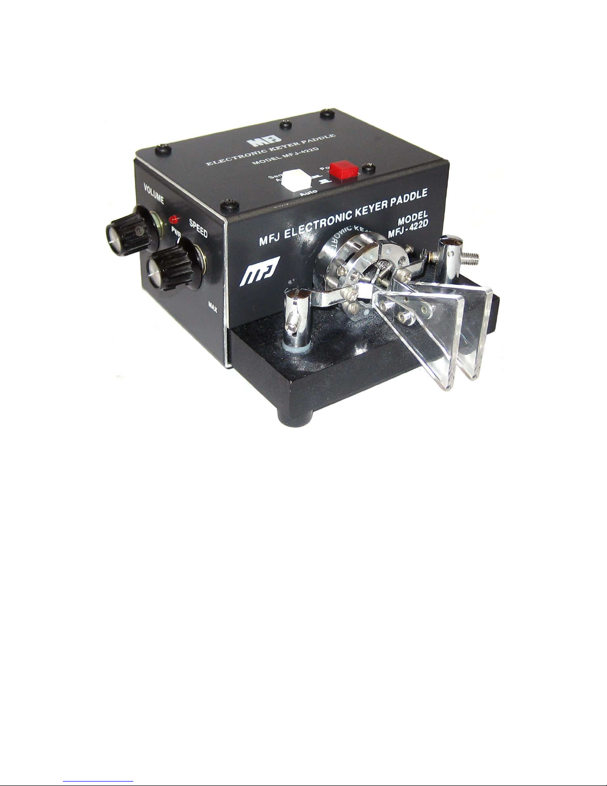
The MFJ-422D
Electronic Keyer Paddle
is an iam ic keyer and paddle com ination. The MFJ-422DX
keyer installs on your MFJ-564 or Bencher type paddle. Both are microprocessor controlled keyers
that provide iam ic key operation and dot-and-dash memory to make sending perfect code easier.
It has tunea le code speed, code weight, and sidetone frequency; it supports oth direct and grid-
lock keying outputs. You also get a choose etween Iam ic Type "A" and Type "B" keying.
Note: All references to the MFJ-422D apply to the MFJ-422DX, unless otherwise stated.
Control Functions
1. The Power utton turns the unit ON and OFF. The power is ON when the utton is locked in
the "in" position and the LED is lit and OFF in the "out" position.
2. The Semi-Auto/Auto utton allows semi-automatic " ug" and manual operations. The keyer
generates dots automatically when a squeeze or single lever is used. Dashes are manually
made. The keyer is completely manual when a straight key is used. Semi-Auto is active when
the switch is in the "in" position and Auto when in the "out" position.
3. The Speed control, located on the left side of the unit, varies the code speed. The speed
range is configured with an internal jumper (JMP9) for 5 to 65 WPM or 10 to 40 WPM. Turn the
control clockwise to increase speed and counter-clockwise to decrease speed. The unit is fac-
tory set to 5 to 65 WPM. To make the speed adjustment less sensitive, change the speed range
to the narrower range of 10 to 40 WPM. To change the speed range the power must e off,
then remove the paddle to access the jumper inside the case. Locate jumper JMP9 next to the
microprocessor and set it to the "H" position.
Note: Power must e off when changing the jumper settings.
4. The Volume control, located on the left side of the unit, adjusts the sidetone level of the inter-
nal speaker. Turn the control clockwise to increase the volume and counter-clockwise to de-
crease the volume.
5. The Weight control varies the code weight from approximately 25 % to 75 %, with the stand-
ard dot defined as 50 % weight. The standard dot-dash-space ratio is 1:3:1 (trimpot at mid-
range). This control is accessed through a small hole on the rear of the unit and may e ad-
justed using a small flat-headed screwdriver. This control is turned clockwise to increase dot
and dash lengths and counter-clockwise to decrease dot and dash lengths.
6. The Tone control sets the desired sidetone pitch from approximately 300 to 1200 Hz. This con-
trol is also accessed through a small hole on the rear of the unit and may e adjusted using a
small flat-headed screwdriver. This control is turned clockwise to raise the pitch and counter-
clockwise to lower the pitch.
7. The Key Output circuit supports oth positive and negative keyed radios. The MFJ-422D can
only key one type of transmitter at a time. This is an internal jumper selected option. The unit
is factory set to direct keying (most solid state radios). To change to grid- lock keying (most
radios with tu e finals) the power must e off, then remove the paddle to access the jumpers
inside the case. Locate jumpers JMP1 and JMP2. JMP2 is directly ehind the RCA jack (J2).
JMP1 is located ehind the power jack (J1). Set
oth
jumpers JMP1 and JMP2 to the "G" posi-
tion. To key a solid state transmitter, set oth jumpers to the "D" position.
Note: Power must e off when changing the jumper settings.