MFRM Leggett & Platt 100 series User manual

©2016 MFRM.All Rights Reserved. MattressFirm.com
Setup Guide Packet
100 • 300 • 500 • 700
©2016 MFRM.All Rights Reserved. MattressFirm.com
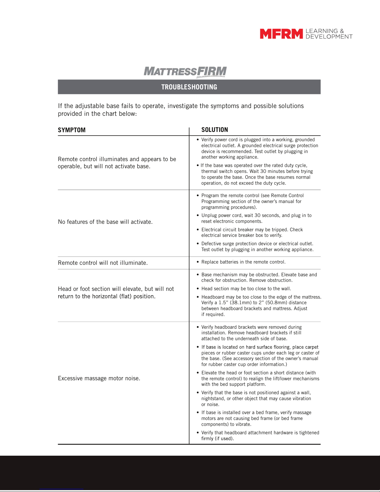
TROUBLESHOOTING
If the adjustable base fails to operate, investigate the symptoms and possible solutions
provided in the chart below:
SYMPTOM SOLUTION
• Verify power cord is plugged into a working, grounded
electrical outlet. A grounded electrical surge protection
device is recommended. Test outlet by plugging in
another working appliance.
• If the base was operated over the rated duty cycle,
thermal switch opens. Wait 30 minutes before trying
to operate the base. Once the base resumes normal
operation, do not exceed the duty cycle.
• Program the remote control (see Remote Control
Programming section of the owner’s manual for
programming procedures).
• Unplug power cord, wait 30 seconds, and plug in to
reset electronic components.
• Electrical circuit breaker may be tripped. Check
electrical service breaker box to verify.
• Defective surge protection device or electrical outlet.
Test outlet by plugging in another working appliance.
• Replace batteries in the remote control.
• Base mechanism may be obstructed. Elevate base and
check for obstruction. Remove obstruction.
• Head section may be too close to the wall.
• Headboard may be too close to the edge of the mattress.
Verify a 1.5” (38.1mm) to 2” (50.8mm) distance
between headboard brackets and mattress. Adjust
if required.
• Verify headboard brackets were removed during
installation. Remove headboard brackets if still
attached to the underneath side of base.
•
pieces or rubber caster cups under each leg or caster of
the base. (See accessory section of the owner’s manual
for rubber caster cup order information.)
• Elevate the head or foot section a short distance (with
the remote control) to realign the lift/lower mechanisms
with the bed support platform.
• Verify that the base is not positioned against a wall,
nightstand, or other object that may cause vibration
or noise.
• If base is installed over a bed frame, verify massage
motors are not causing bed frame (or bed frame
components) to vibrate.
• Verify that headboard attachment hardware is tightened
Remote control illuminates and appears to be
operable, but will not activate base.
No features of the base will activate.
Remote control will not illuminate.
Head or foot section will elevate, but will not
Excessive massage motor noise.
6/16
© 2016 Mattress Firm, Inc.
©2016 MFRM.All Rights Reserved. MattressFirm.com
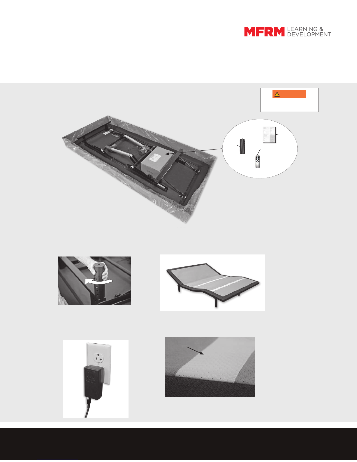
QUICK SETUP GUIDE: 100 SERIES
START HERE. . .
Verify contents; inspect for damage.
A - (4) Legs
B - (1) Remote Control
C - (1) Warranty Activation Card
ATLEASTTWOPEOPLEARERECOMMENDED
FOR HANDLING AND MOVING ADJUSTABLE
BASE.
WARNINGWARNING
3PLUG POWER CORD INTO A WORKING GROUNDED
ELECTRICAL OUTLET. Note: An electrical surge protection
device is recommended (not included). 4INSTALLMATTRESSTOCOMPLETESETUP.Adjustablebaseisequipped
with a MicroHook™ system to captivate the mattress
If adjustable base will not operate, refer to the Troubleshooting Guide or
detailed instructions in the owner’s manual. To download a copy of the
owner’s manual, visit LPAdjustablebeds.com/om/mattressfirm or call toll
free: 844-MATT-FRM.
MicroHook™
DETAIL
2UNCOIL MAIN POWER CORD AND EXTEND OUT HEAD
END OF BASE. DO NOT WEAVE CORD THROUGH BASE
STRUCTURE.
ROTATE BASE OVER SO IT IS RESTING ON ITS LEGS.
NOTE: BASE SHOWN
ARTICULATED
C
B
A
1REMOVE HARDWARE BOX.
INSTALL LEGS. Screw legs into base frame. NOTE: Push pin in
on leg to adjust leg height (achieve leg height of 6 inches to 10
inches).

©2016 MFRM.All Rights Reserved. MattressFirm.com
123
56
START HERE. . .
Verify contents; inspect for damage.
A - (4) Legs
B - (1) Remote Control w/ (3) AAA Batteries
C - (1) Control Box
(factory attached to underside of base)
D - (1) Power Supply
(includes power brick, electrical feed cord, and
electrical power cord)
E - (1) Warranty Activation Card
61 / 879631RDEc - 42610399
© 2016 Mattress Firm, Inc.
REMOVE HARDWARE BOX.
INSTALL LEGS. Screw legs into base frame. NOTE: Push pin
in on leg to adjust leg height (achieve leg height of 6 inches to
10 inches).
UNCOIL MAIN POWER CORD AND EXTEND OUT
HEAD END OF BASE. DO NOT WEAVE CORD
THROUGH BASE STRUCTURE.
ROTATE BASE OVER SO IT IS RESTING ON ITS LEGS.
REMOVE PLASTIC PACKAGING.
PLUG POWER CORD INTO A WORKING, GROUNDED
ELECTRICAL OUTLET. Note: An electrical surge protection
device is recommended (not included).
4
INSTALL (3) AAA BATTERIES IN REMOTECONTROL.
OPERATE REMOTE CONTROL TO VERIFY BASE
FUNCTIONS PROPERLY.
QUICK SETUP GUIDE
n 300
AT LEAST TWO PEOPLE ARE
RECOMMENDED FOR HANDLING AND
MOVING ADJUSTABLE BASE.
WARNINGWARNING
INSTALL MATTRESS TO COMPLETE SETUP.
Adjustable base is equipped with a Micro Hook™
system to secure the mattress.
TEST UNDER-BED LIGHTING. Press under-bed light
switch, indicated by button icon, located on both
sides of base.
If adjustable base will not operate, referto the Troubleshooting
Guide or detailed instructions in the owners manual. To download
a copy of the owners manual, visit www.lpadjustablebeds.com/
om/mattressfi r m or calltoll free: 844-MATT-FRM.
Micro Hook™
DETAIL
ELECTRICAL
POWER CORD
pre-attached
to base
BATTERY
COMPARTMENT
DOOR
TABS
POSITIVE (+) END
PRESS IN ON TAB AND LIFT OUT TO
REMOVE BATTERY COMPARTMENT
DOOR. INSERT TABS IN TAB SLOTS
AND SNAP IN TO REPLACE.
NEGATIVE (-) END UNDER-BED LIGHT
SWITCH INDICATOR
E
A
B
D
C
QUICK SETUP GUIDE: 300 SERIES

©2016 MFRM.All Rights Reserved. MattressFirm.com
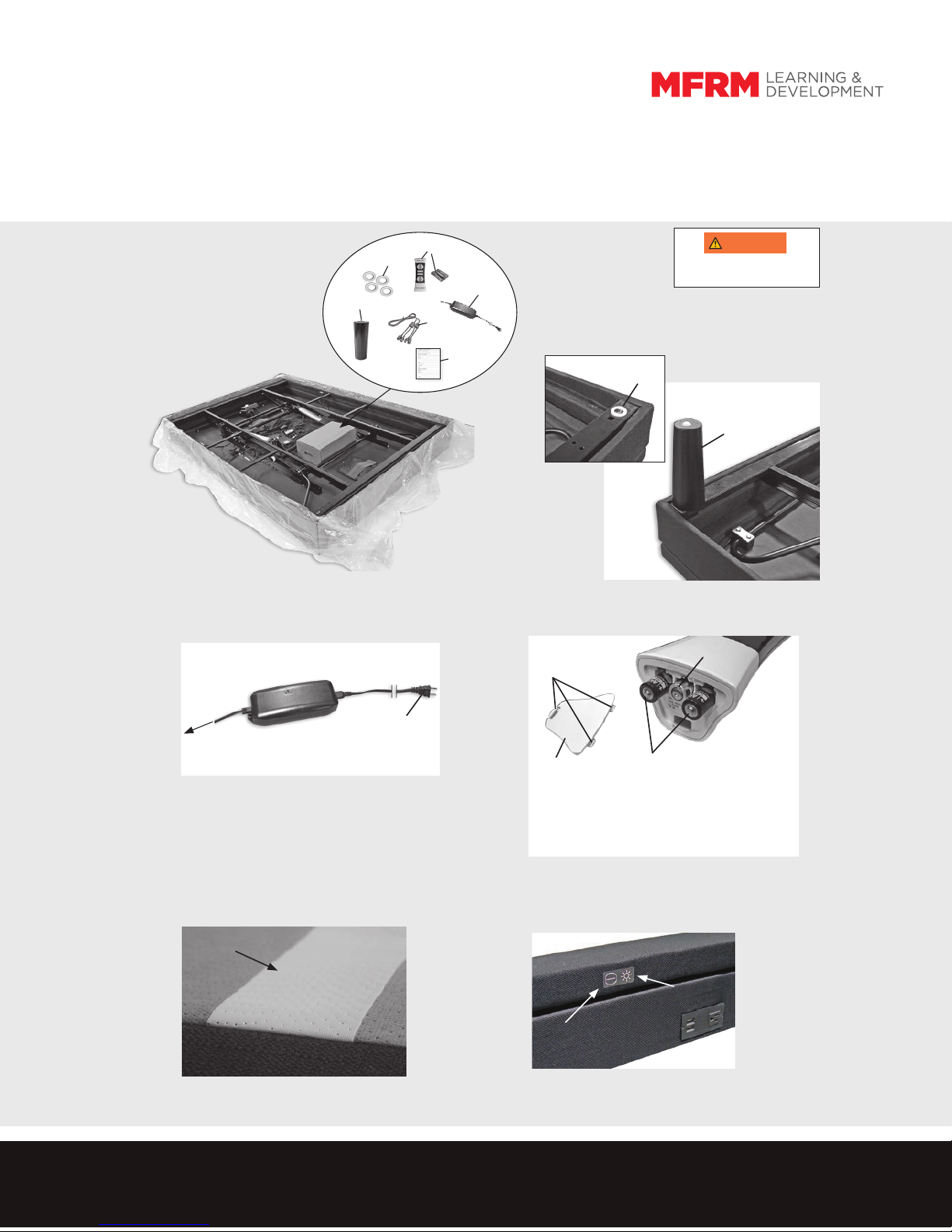
QUICK SETUP GUIDE: 500 SERIES
45
START HERE. . .
Verify contents; inspect for damage.
A - (4) Wood Legs
B - (4) Plastic Washers (for leg installation)
C - (1) Remote Control w/ (3) AAA Batteries
D - (1) Power Supply (includes power brick, electrical
feed cord, and electrical power cord)
E - (1) Dual Sync Cable (split sizes only)
F - (1) Warranty Activation Card
23
1REMOVE HARDWARE BOX.
PLACE PLASTIC WASHERS OVER THREADED INSERTS IN
CORNERS OF BASE FRAME.
SCREW LEGS INTO THREADED INSERTS, KEEPING PLASTIC
WASHER BETWEEN LEG AND THREADED INSERT.
AT LEAST TWO PEOPLE ARE
RECOMMENDED FOR HANDLING AND
MOVING ADJUSTABLE BASE.
WARNINGWARNING
ROTATE BASE OVER SO IT IS RESTING ON ITS LEGS.
REMOVE PLASTIC PACKAGING.
INSTALL (3) AAA BATTERIES IN REMOTE CONTROL. OPERATE REMOTE
CONTROL TO VERIFY BASE FUNCTIONS PROPERLY.
BATTERY
COMPARTMENT
DOOR
TABS
POSITIVE (+) END
NEGATIVE (-) END
PRESS IN ON TAB AND LIFT OUT TO
REMOVE BATTERY COMPARTMENT
DOOR. INSERT TABS IN TAB SLOTS
AND SNAP IN TO REPLACE.
F
E
D
A
B
PLUG POWER CORD INTO A WORKING GROUNDED ELECTRICAL OUTLET.
Note: An electrical surge protection device is recommended (not included).
ELECTRICAL
POWER CORD
pre-attached to base
LEG
WASHER
INSTALL MATTRESS TO COMPLETE SETUP. Adjustable base is
equipped with a MicroHook™ system to captivate the mattress.
MicroHook™
DETAIL
C
TEST UNDER-BED LIGHTING / FLAT FEATURE indicated by
power icon and flat icon, located on both sides of base. Press
in on underbed light switch to turn underbed light on and off.
Press and hold flat switch to lower base to level position.
If adjustable base will not operate, refer to the Troubleshooting Guide
or detailed instructions in the owner’s manual. To download a copy of
the owner’s manual, visit LPAdjustablebeds.com/om/mattressfirm or
call toll free: 844-MATT-FRM.
UNDER-BED LIGHT
SWITCH INDICATOR
FLAT SWITCH
INDICATOR
©2016 MFRM.All Rights Reserved. MattressFirm.com
QUICK SETUP GUIDE: 700 SERIES
45
23
AT LEAST TWO PEOPLE ARE
RECOMMENDED FOR HANDLING AND
MOVING ADJUSTABLE BASE.
WARNINGWARNING
ROTATE BASE OVER SO IT IS RESTING ON ITS LEGS.
REMOVE PLASTIC PACKAGING.
INSTALL (3) AAA BATTERIES IN REMOTE CONTROL. OPERATE REMOTE
CONTROL TO VERIFY BASE FUNCTIONS PROPERLY.
BATTERY
COMPARTMENT
DOOR
TABS
POSITIVE (+) END
NEGATIVE (-) END
PRESS IN ON TAB AND LIFT OUT TO
REMOVE BATTERY COMPARTMENT
DOOR. INSERT TABS IN TAB SLOTS
AND SNAP IN TO REPLACE.
PLUG POWER CORD INTO A WORKING GROUNDED ELECTRICAL OUTLET.
Note: An electrical surge protection device is recommended (not included).
ELECTRICAL
POWER CORD
pre-attached to base
1REMOVE HARDWARE BOX.
PLACE PLASTIC WASHERS OVER THREADED INSERTS IN
CORNERS OF BASE FRAME.
SCREW LEGS INTO THREADED INSERTS, KEEPING PLASTIC
WASHER BETWEEN LEG AND THREADED INSERT.
LEG
WASHER
INSTALL MATTRESS TO COMPLETE SETUP. Adjustable base is
equipped with a MicroHook™ system to captivate the mattress.
MicroHook™
DETAIL
TEST UNDER-BED LIGHTING / FLAT FEATURE indicated by
power icon and flat icon, located on both sides of base. Press
in on underbed light switch to turn under-bed light on and off.
Press and hold flat switch to lower base to level position.
If adjustable base will not operate, refer to the Troubleshooting Guide or
detailed instructions in the owner’s manual. To download a copy of the
owner’s manual, visit LPAdjustablebeds.com/om/mattressfirm or call toll
free: 844-MATT-FRM.
UNDER-BED LIGHT
SWITCH INDICATOR
FLAT SWITCH
INDICATOR
START HERE. . .
Verify contents; inspect for damage.
A - (4) Wood Legs
B
-
(4) Plastic Washers (for leg installation)
C
-
(1) Remote Control w/ (3) AAA Batteries
D
-(1) Power Supply (includes power brick, electrical
feed cord, and electrical power cord)
E - (1) Dual Sync Cable (split sizes only)
F - (1) Warranty Activation Card
F
E
D
A
B
C
This manual suits for next models
3
Table of contents
Popular Indoor Furnishing manuals by other brands


MultiTable
MultiTable FlexTable Assembly manual

Skovby
Skovby SM769 Assembly & Maintenance Instructions

W.Schillig
W.Schillig BAJAZZO Aassembly Instructions

U-Line
U-Line H-1485 technical information

Lightolier
Lightolier LytePoints 56946 specification

ROBERTO FIORE
ROBERTO FIORE Cabinets To Go WD2430 Assembly instructions


